

26 |
Broadband Microstrip Antennas |
[82]Ray, K. P., and G. Kumar, ‘‘Compact Gap-Coupled Shorted 90° Sectoral Microstrip Antennas for Broadband and Dual Band Operations,’’ Microwave Optical Tech. Letters, Vol. 26, No. 3, 2000, pp. 143–145.
[83]Waterhouse R. B., ‘‘Broadband Stacked Shorted Patch,’’ Electronics Letters, Vol. 35, No. 2, 1999, pp. 98–99.
[84]Plessis, M. Du., and J. H. Cloete, ‘‘Tuning Stub for Microstrip Patch Antenna,’’
IEEE AP-S Int. Symp. Digest, June 1993, pp. 964–967.
[85]Ray, K. P., and G. Kumar, ‘‘Tunable and Dual-Band Circular Microstrip Antenna with Stubs,’’ IEEE Trans. Antennas Propagation, Vol. 48, July 2000, pp. 1036–1039.
[86]Bhartia, P., and I. J. Bahl, ‘‘A Frequency Agile Microstrip Antenna,’’ IEEE AP-S Int. Symp. Digest, May 1982, pp. 304–307.
[87]Maci, S., and G. B. Gentili, ‘‘Dual-Frequency Patch Antennas,’’ IEEE AP Magazine, Vol. 39, No. 6, 1997, pp. 13–19.
[88]Schaubert, H., et al., ‘‘Microstrip Antennas with Frequency Agility and Polarization Diversity,’’ IEEE Trans. Antennas Propagation, Vol. AP-29, January 1981, pp.118–123.
[89]Richards, W. F., S. E. Davidson, and S. A. Long, ‘‘Dual Band Reactively Loaded Microstrip Antenna,’’ IEEE Trans. Antennas Propagation, Vol. AP-33, May 1985, pp. 556–561.
[90]Long, S. A., and M. D. Walton, ‘‘A Dual-Frequency Stacked Circular-Disc Antenna,’’ IEEE Trans. Antennas Propagation, Vol. AP-27, March 1979, pp. 270–273.
[91]Syankal, M., and H. R. Hassani, ‘‘Characteristics of Stacked Rectangular and Triangular Patch Antennas for Dual Band Application,’’ Proc. IEE 8th International Conference on Antennas and Propagation, Edinburgh, Scotland, March 1993.
[92]Yazdi, M. L., M. Himdi, and J. P. Daniel, ‘‘Aperture-Coupled Microstrip Antenna
for Dual Frequency Operation,’’ Electronics Letters, Vol. 29, No. 17, 1993,
pp. 1506–1508.
[93]Sharma, P. C., and K. C. Gupta, ‘‘Analysis and Optimized Design of Single Feed Circularly Polarized Microstrip Antennas,’’ IEEE Trans. Antennas Propagation, Vol. 31, No. 6, 1983, pp. 949–955.
[94]Targonski, S. D., and D. M. Pozar, ‘‘Design of Wideband Circularly Polarized
Aperture-Coupled Microstrip Antennas,’’ IEEE Trans. Antennas Propagation, Vol. 41, No. 2, 1993, pp. 214–220.
[95]Pozar, D. M., and S. M. Duffy, ‘‘A Dual-Band Circularly Polarized Aperture-Coupled Stacked Microstrip Antenna for Global Positioning Satellite,’’ IEEE Trans. Antennas Propagation, Vol. 45, No. 11, 1997, pp. 1618–1625.
[96]Bhattacharya, A. K., and L. Shafai, ‘‘A Wider Band Microstrip Antenna for Circular Polarization,’’ IEEE Trans. Antennas Propagation, Vol. 36, No. 2, 1988, pp. 157–163.
[97]Kraft, U. R., ‘‘An Experimental Study on 2 × 2 Sequential Rotation Arrays with Circularly Polarized Microstrip Radiators,’’ IEEE Trans. Antennas Propagation, Vol. AP-45, No. 10, 1997, pp. 1459–1466.
[98]Iwasaki, H., T. Nakajima, and Y. Suzuki, ‘‘Gain Improvement of Circularly Polarized Array Antenna Using Linearly Polarized Elements,’’ IEEE Trans. Antennas Propagation, Vol. 43, No. 6, 1995, pp. 604–608.
An Introduction to Microstrip Antennas |
27 |
[99]Ray, K. P., et al., ‘‘Broadband Planar Rectangular Monopole Antennas,’’ Microwave Optical Tech. Letters, Vol. 28, No. 1, 2001, pp. 55–59.
[100]Honda, S., et al., ‘‘A Disc Monopole Antenna with 1:8 Impedance BW and Omnidirectional Radiation Pattern,’’ Proc. ISAP, Sapporo, Japan, 1992, pp. 1145–1148.
[101]Hammoud, M., P. Poey, and F. Colombel, ‘‘Matching the Input Impedance of a Broadband Disc Monopole,’’ Electronics Letters, Vol. 29, February 1993, pp. 406–407.
[102]Agarwall, N. P., G. Kumar, and K. P. Ray, ‘‘Wideband Planar Monopole Antennas,’’
IEEE Trans. Antennas Propagation, Vol. 46, No. 2, 1998, pp. 294–295.
2
Regularly Shaped Broadband MSAs
2.1 Introduction
An MSA in its simple form consists of a radiating patch on one side of a thin dielectric substrate backed by a ground plane. The radiating patch could be of any arbitrary shape, but it is generally taken as a regular shape for the ease of analysis and understanding of the antenna characteristics [1–6]. This chapter considers various regularly shaped MSAs, such as rectangular, circular, semicircular, equilateral triangular, 30°–60°–90° triangular, and annular ring patches. In addition, their characteristics, such as input impedance, BW, radiation pattern, and gain for various substrates, are described.
The BW of the MSA is directly proportional to the substrate thickness h and inversely proportional to the square root of its dielectric constant er as described in Chapter 1. As a result, a thicker substrate with a low dielectric constant is generally used to obtain broad BW. One of the commonly used substrates for MSA is fiberglass-reinforced synthetic substrate, whose er is typically between 2.1 to 2.6. This substrate has low dielectric loss (tan d in the range of 0.0006 to 0.002) resulting in better efficiency, h . For low-cost applications or for initial design and testing, inexpensive glass-epoxy substrate (er in the range of 3.8 to 4.7) is used. Sometimes, air or foam substrate (er = 1–1.1) is used to enhance the BW. Alternatively, suspended microstrip configuration can be used; this increases the total thickness and decreases the effective dielectric constant of the patch.
29
30 |
Broadband Microstrip Antennas |
2.2 RMSAs
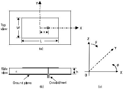
One of the simplest and widely used MSA configurations is the RMSA. Figure 2.1 shows the top and side views of a coaxial-fed RMSA along with the coordinate system. A rectangular patch is defined by its length L and width W. For a simple microstrip line, the width is much smaller than the wavelength. However, for the RMSA, the width is comparable to the wavelength to enhance the radiation from the edges. Since the substrate thickness is much smaller than the wavelength, the RMSA is considered to be a two-dimensional planar configuration for analysis.
For the fundamental TM10 mode, the length L should be slightly less than l/2, where l is the wavelength in the dielectric medium. Here, l is equal to l0 /√ee , where l0 is the free-space wavelength and ee is the effective dielectric constant of the patch. The value of ee is slightly less than er , because the fringing fields around the periphery of the patch are not confined in the dielectric substrate but are also spread in the air as shown in Figure 2.2(a). The expression for calculating the value of ee is given in Appendix B, which also accounts for the dispersion effect. However, for quick analysis or design, the following approximate formula for ee could be used [1]:
Figure 2.1 (a) Top and (b) side views of a rectangular MSA and (c) coordinate system.
|
|
|
|
|
|
|
|
|
|
Regularly Shaped Broadband MSAs |
31 |
|||||||||||||||||||||||||||||||||
|
|
|
|
|
|
|
|
|
|
|
|
|
|
|
|
|
|
|
|
|
|
|
|
|
|
|
|
|
|
|
|
|
|
|
|
|
|
|
|
|
|
|
|
|
|
|
|
|
|
|
|
|
|
|
|
|
|
|
|
|
|
|
|
|
|
|
|
|
|
|
|
|
|
|
|
|
|
|
|
|
|
|
|
|
|
|
|
|
|
|
|
|
|
|
|
|
|
|
|
|
|
|
|
|
|
|
|
|
|
|
|
|
|
|
|
|
|
|
|
|
|
|
|
|
|
|
|
|
|
|
|
|
|
|
|
|
|
|
|
|
|
|
|
|
|
|
|
|
|
|
|
|
|
|
|
|
|
|
|
|
|
|
|
|
|
|
|
|
|
|
|
|
|
|
|
|
|
|
|
|
|
|
|
|
|
|
|
|
|
|
|
|
|
|
|
|
|
|
|
|
|
|
|
|
|
|
|
|
|
|
|
|
|
|
|
|
|
|
|
|
|
|
|
|
|
|
|
|
|
|
|
|
|
|
|
|
|
|
|
|
|
|
|
|
|
|
|
|
|
|
|
|
|
|
|
|
|
|
|
|
|
|
|
|
|
|
|
|
|
|
|
|
|
|
|
|
|
|
|
|
|
|
|
|
|
|
|
|
|
|
|
|
|
|
|
|
|
|
|
|
|
|
|
|
|
|
|
|
|
|
|
|
|
|
|
|
|
|
|
|
|
|
|
|
|
|
|
|
|
|
|
|
|
|
|
|
|
|
|
|
|
|
|
|
|
|
|
|
|
|
|
|
|
|
|
|
|
|
|
|
|
|
|
|
|
|
|
|
|
|
|
|
|
|
|
|
|
|
|
|
|
|
|
|
|
|
|
|
|
|
|
|
|
|
|
|
|
|
|
|
|
|
|
|
|
|
|
|
|
|
|
|
|
|
|
|
|
|
|
|
|
|
|
|
|
|
|
|
|
|
|
|
|
|
|
|
|
|
|
|
|
|
|
|
|
|
|
|
|
|
|
|
|
|
|
|
|
|
|
|
|
|
|
|
|
|
|
|
|
|
|
|
|
|
|
|
|
|
|
|
|
|
|
|
|
|
|
|
|
|
|
|
|
|
|
|
|
|
|
|
|
|
|
|
|
|
|
|
|
|
|
|
|
|
|
|
|
|
|
|
|
|
|
|
|
|
|
|
|
|
|
|
|
|
|
|
|
|
|
|
|
|
|
|
|
|
|
|
|
|
|
|
|
|
|
|
|
|
|
|
|
|
|
|
|
|
|
|
|
|
|
|
|
|
|
|
|
|
|
|
|
|
|
|
|
|
|
|
|
|
|
|
|
|
|
|
|
|
|
|
|
|
|
|
|
|
|
|
|
|
|
|
|
|
|
|
|
|
|
|
|
|
|
|
|
|
|
|
|
|
|
|
|
|
|
|
|
|
|
|
|
|
|
|
|
|
|
|
|
|
|
|
|
|
|
|
|
|
|
|
|
|
|
|
|
|
|
|
|
|
|
|
|
|
|
|
|
|
|
|
|
|
|
|
|
|
|
|
|
|
|
|
|
|
|
|
|
|
|
|
|
|
|
|
|
|
|
|
|
|
|
|
|
|
|
|
|
|
|
|
|
|
|
|
|
|
|
|
|
|
|
|
|
|
|
|
|
|
|
|
|
|
|
|
|
|
|
|
|
|
|
|
|
|
|
|
|
|
|
|
|
|
|
|
|
|
|
|
|
|
|
|
|
|
|
|
|
|
|
|
|
|
|
|
|
|
|
|
|
|
|
|
|
|
|
|
|
|
|
|
|
|
|
|
|
|
|
|
|
|
|
|
|
|
|
|
|
|
|
|
|
|
|
|
|
|
|
|
|
|
|
|
|
|
|
|
|
|
|
|
|
|
|
|
|
|
|
|
|
|
|
|
|
|
|
|
|
|
|
|
|
|
|
|
|
|
|
|
|
|
|
|
|
|
|
|
|
|
|
|
|
|
|
|
|
|
|
|
|
|
|
|
|
|
|
|
|
|
|
|
|
|
|
|
|
|
|
|
|
|
|
|
|
|
|
|
|
|
|
|
|
|
|
|
|
|
|
|
|
|
|
|
|
|
|
|
|
|
|
|
|
|
|
|
|
|
|
|
|
|
|
|
|
|
|
|
|
|
|
|
|
|
|
|
|
|
|
|
|
|
|
|
|
|
|
|
|
|
|
|
|
|
|
|
|
|
|
|
|
|
|
|
|
|
|
|
|
|
|
|
|
|
|
|
|
|
|
|
|
|
|
|
|
|
|
|
|
|
|
|
|
|
|
|
|
|
|
|
|
|
|
|
|
|
|
|
|
|
|
|
|
|
|
|
|
|
|
|
|
|
|
|
|
|
|
|
|
|
|
|
|
|
|
|
|
|
|
|
|
|
|
|
|
|
|
|
|
|
|
|
|
|
|
|
|
|
|
|
|
|
|
|
|
|
|
|
|
|
|
|
|
|
|
|
|
|
|
|
|
|
|
|
|
|
|
|
|
|
|
|
|
|
|
|
|
|
|
|
|
|
|
|
|
|
|
|
|
|
|
|
|
|
|
|
|
|
|
|
|
|
|
|
|
|
|
|
|
|
|
|
|
|
|
|
|
|
|
|
|
|
|
|
|
|
|
|
|
|
|
|
|
|
|
|
|
|
|
|
|
|
|
|
|
|
|
|
|
|
|
|
|
|
|
|
|
|
|
|
|
|
|
|
|
|
|
|
|
|
|
|
|
|
|
|
|
|
|
|
|
|
|
|
|
|
|
|
|
|
|
|
|
|
|
|
|
|
|
|
|
|
|
|
|
|
|
|
|
|
|
|
|
|
|
|
|
|
|
|
|
|
|
|
|
|
|
|
|
|
|
|
|
|
|
|
|
|
|
|
|
|
|
|
|
|
|
|
|
|
|
|
|
|
|
|
|
|
|
|
|
|
|
|
|
|
|
|
|
|
|
|
|
|
|
|
|
|
|
|
|
|
|
|
|
|
|
|
|
|
|
|
|
|
|
|
|
|
|
|
|
|
|
|
|
|
|
|
|
|
|
|
|
|
|
|
|
|
|
|
|
|
|
|
|
|
|
|
|
|
|
|
|
|
|
|
|
|
|
|
|
|
|
|
|
|
|
|
|
|
|
|
|
|
|
|
|
|
|
|
|
|
|
|
|
|
|
|
|
|
|
|
|
|
|
|
|
|
|
|
|
|
|
|
|
|
|
|
|
|
|
|
|
|
|
|
|
|
|
|
|
|
|
|
|
|
|
|
|
|
|
|
|
|
|
|
|
|
|
|
|
|
|
|
|
|
|
|
|
|
|
|
|
|
|
|
|
|
|
|
|
|
|
|
|
|
|
|
|
|
|
|
|
|
|
|
|
|
|
|
|
|
|
|
|
|
|
|
|
|
|
|
|
|
|
|
|
|
|
|
|
|
|
|
|
|
|
|
|
|
|
|
|
|
|
|
|
|
|
|
|
|
|
|
|
|
|
|
|
|
|
|
|
|
|
|
|
|
|
|
|
|
|
|
|
|
|
|
|
|
|
|
|
|
|
|
|
|
|
|
|
|
|
|
|
|
|
|
|
|
|
|
|
|
|
|
|
|
|
|
|
|
|
|
|
|
|
|
|
|
|
|
|
|
|
|
|
|
|
|
|
|
|
|
|
|
|
|
|
|
|
|
|
|
|
|
|
|
|
|
|
|
|
|
|
|
|
|
|
|
|
|
|
|
|
|
|
|
|
|
|
|
|
|
|
|
|
|
|
|
|
|
|
|
|
|
|
|
|
|
|
|
|
|
|
|
|
|
|
|
|
|
|
|
|
|
|
|
|
|
|
|
|
|
|
|
|
|
|
|
|
|
|
|
|
|
|
|
|
|
|
|
|
|
|
|
|
|
|
|
|
|
|
|
|
|
|
|
|
|
|
|
|
|
|
|
|
|
|
|
|
|
|
|
|
|
|
|
|
|
|
|
|
|
|
|
|
|
|
|
|
|
|
|
|
|
|
|
|
|
|
|
|
|
|
|
|
|
|
|
|
|
|
|
|
|
|
|
|
|
|
|
|
|
|
|
|
|
|
|
|
|
|
|
|
|
|
|
|
|
|
|
|
|
|
|
|
|
|
|
|
|
|
|
|
|
|
|
|
|
|
|
|
|
|
|
|
|
|
|
|
|
|
|
|
|
|
|
|
|
|
|
|
|
|
|
|
|
|
|
|
|
|
|
|
|
|
|
|
|
|
|
|
|
|
|
|
|
|
|
|
|
|
|
|
|
|
|
|
|
|
|
|
|
|
|
|
|
|
|
|
|
|
|
|
|
|
|
|
|
|
|
|
|
|
|
|
|
|
|
|
|
|
|
|
|
|
|
|
|
|
|
|
|
|
|
|
|
|
|
|
|
|
|
|
|
|
|
|
|
|
|
|
|
|
|
|
|
|
|
|
|
|
|
|
|
|
|
|
|
|
|
|
|
|
|
|
|
|
|
|
|
|
|
|
|
|
|
|
|
|
|
|
|
|
|
|
|
|
|
|
|
|
|
|
|
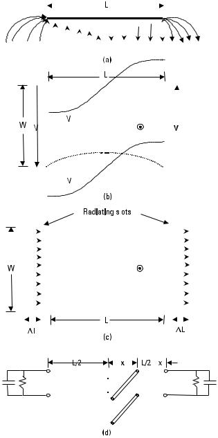
Figure 2.2 Fundamental TM10 mode of RMSA: (a) E-field distribution, (b) ( —— ) voltage and ( ? ? ? ) current variation, (c) two radiating slots, and (d) equivalent transmission line model.
32 |
Broadband Microstrip Antennas |
|
|||||
|
2 |
|
2 |
F |
|
W G |
−1/2 |
|
(er + 1) |
+ |
(er − 1) |
|
1 + |
10h |
|
ee = |
|
|
|
|
(2.1) |
||
The fundamental TM10 mode implies that the field varies one l /2 cycle along the length, and there is no variation along the width of the patch. The variation of voltage V around the periphery and the current I along the length is shown in Figure 2.2(b). Along the width of the patch, the voltage is maximum and current is minimum due to the open end. It may be observed from Figure 2.2(a) that the vertical components of the electric field (E-field) at the two edges along the width are in opposite directions and hence cancel one another in the broadside direction, whereas the horizontal components are in same direction and hence combine in the broadside direction. Therefore, the edges along the width are termed as radiating edges. The fields due to the sinusoidal distribution along the length cancel in the broadside direction, and hence the edges along the length are known as nonradiating edges. The fringing fields along the width can be modeled as radiating slots as shown in Figure 2.2(c).
An RMSA operating at TM10 mode can be visualized as a transmission line, because the field is uniform along the width and varies sinusoidally along the length. The fringing fields along the edges and radiation from the slots are modeled by their equivalent capacitance and radiation resistance, respectively as shown in Figure 2.2(d).
To account for the fringing fields, instead of adding the capacitor at the edges, the dimensions around the periphery of the patch can be extended outwards. This can be explained in terms of the two parallel rectangular plates of dimensions L and W, which are separated by a dielectric substrate of thickness h . If the fringing fields along the periphery are ignored, then
the capacitance of the two parallel plates will be |
|
|||
C = eo er |
WL |
(2.2) |
||
h |
|
|||
|
|
|||
However, due to the fringing capacitance (because of the fringing fields), the effective capacitance C e of the two parallel plates increases. One of the ways to account for the fringing capacitance is to extend the dimensions
of the plate outward, and the value of C e can be calculated from: |
|
|||
C e = eo er |
We |
L e |
(2.3) |
|
h |
|
|
||
|
|
|
|
|

Regularly Shaped Broadband MSAs |
33 |
where, L e and We are the effective dimensions and are equal to: |
|
L e = L + 2DL |
(2.4) |
We = W + 2DW |
(2.5) |
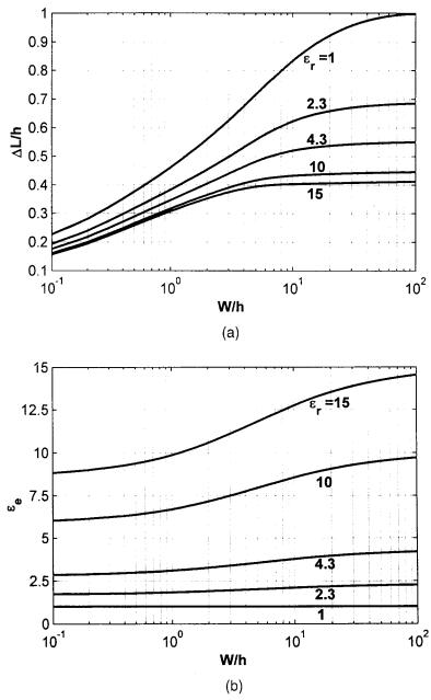
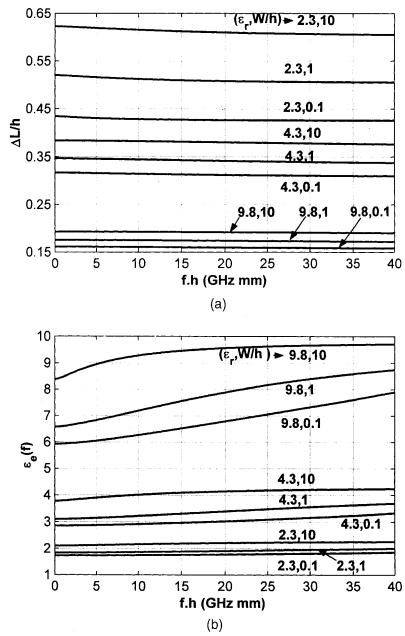
The DL and DW are the extensions along the L and W, respectively. The expressions for calculating their values are given in Appendix B, which also accounts for the dispersion effect. Using these closed-form expressions, the variations of DL /h and ee with W /h for various values of er are given in Figure 2.3. For a given value of er , the values of DL /h and ee increase with an increase in W /h. These plots do not account for the dispersion effect at the higher frequencies. As the frequency increases, the electrical thickness of the substrate (i.e., h /l0 ) increases. The variations of DL /h and ee with f.h (or h /l0 ) for three values of er (2.3, 4.3, and 9.8) and a thickness of W /h (0.1, 1, and 10), obtained from expressions given in Appendix B, are plotted in Figure 2.4. The frequency is in gigahertz, and h is in millimeters. As the frequency increases, the fields are more confined to the substrate,
hence DL /h decreases and ee increases.
For RMSA, generally W >> h, so for quick analysis or design, the extension in length may be approximately calculated by the following simple formula:
DL = |
|
h |
|
|
(2.6) |
|||||||
|
√ |
|
|
|
|
|
|
|||||
|
ee |
|
|
|
||||||||
Since the effective length of the patch is |
equal to l/2, it can be |
|||||||||||
calculated for a given resonance frequency f 0 as: |
|
|
|
|
||||||||
L e = L + 2DL = |
|
l 0 |
|
|
c |
|||||||
|
|
|
|
|
|
= |
|
|
|
|
(2.7) |
|
|
|
|
|
|
|
|
|
|
|
|||
2 √ee |
2f 0 |
|
||||||||||
|
|
√ee |
||||||||||
where c = velocity of light in free space = 3 × 1010 cm/sec. This expression simplifies to
15
L e = (2.8) f 0 √ee
where L e is in cm and f 0 is in gigahertz. For a given length L , f 0 is calculated from
34 |
Broadband Microstrip Antennas |
Figure 2.3 Variations of (a) DL /h and (b) ee for various values of er and W /h.
Regularly Shaped Broadband MSAs |
35 |
Figure 2.4 Variation of (a) DL /h and (b) ee ( f ) with f.h for various values of er and W /h.