

16 |
|
|
|
|
Broadband Microstrip Antennas |
||||||||||||
|
|
|
|
|
|
|
|
|
|
|
|
|
|
|
|
|
|
|
|
|
|
|
|
|
|
|
|
|
|
|
|
|
|
|
|
|
|
|
|
|
|
|
|
|
|
|
|
|
|
|
|
|
|
|
|
|
|
|
|
|
|
|
|
|
|
|
|
|
|
|
|
|
|
|
|
|
|
|
|
|
|
|
|
|
|
|
|
|
|
|
|
|
|
|
|
|
|
|
|
|
|
|
|
|
|
|
|
|
|
|
|
|
|
|
|
|
|
|
|
|
|
|
|
|
|
|
|
|
|
|
|
|
|
|
|
|
|
|
|
|
|
|
|
|
|
|
|
|
|
|
|
|
|
|
|
|
|
|
|
|
|
|
|
|
|
|
|
|
|
|
|
|
|
|
|
|
|
|
|
|
|
|
|
|
|
|
|
|
|
|
|
|
|
|
|
|
|
|
|
|
|
|
|
|
|
|
|
|
|
|
|
|
|
|
|
|
|
|
|
|
|
|
|
|
|
|
|
|
|
|
|
|
|
Figure 1.6 Various direct-coupled multiresonators: (a) three RMSAs direct-coupled along radiating edges, (b) three RMSAs direct-coupled along nonradiating edges, and (c) five direct-coupled RMSAs.
1.5.4.1 Electromagnetically Coupled MSAs
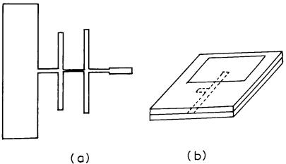
In the electromagnetically coupled MSA, one or more patches at the different dielectric layers are electromagnetically coupled to the feed line located at the bottom dielectric layer as shown in Figure 1.3(b). Alternatively, one of the patches is fed by a coaxial probe and the other patch is electromagnetically coupled. Either the bottom or top patch is fed with a coaxial probe as shown in Figure 1.7. The patches can be fabricated on different substrates, and accordingly the patch dimensions are to be optimized so that the resonance frequencies of the patches are close to each other to yield broad BW. These
Figure 1.7 An electromagnetically coupled MSA, in which (a) the bottom patch is fed and (b) the top patch is fed.
An Introduction to Microstrip Antennas |
17 |
two layers may be separated by either air-gap or foam yielding BW of 15–30% [50–56].
1.5.4.2 Aperture-Coupled MSAs
In the aperture-coupled MSA, the field is coupled from the microstrip feed line placed on the other side of the ground plane to the radiating patch through an electrically small aperture/slot in the ground plane, as shown in Figure 1.3(c). Two different dielectric substrates could be chosen, one for the patch and the other for the feed line to optimize the individual performances. The coupling to the patch from the feed line can be maximized by choosing the optimum shape of the aperture [14–16]. Two patches of rectangular or circular shapes, which are stacked on each other in different dielectric layers yield around 30% BW [57–60]. A BW of nearly 70% has been obtained by stacking patches with resonant apertures [61].
The multilayer broadband MSAs, unlike single-layer multiresonator configurations, show a very small degradation in radiation pattern over the complete VSWR BW. The drawback of these structures is the increased height, which is not desirable for conformal applications and increased back radiation for aperture-coupled MSAs. Multilayered configurations using both electromagnetic as well as aperture coupling are described in Chapter 4.
1.5.5 Stacked Multiresonator MSAs
The planar and stacked multiresonator techniques are combined to further increase the BW and gain. A probe-fed single rectangular or circular patch located on the bottom layer has been used to excite multiple rectangular or circular patches on the top layer, respectively [62, 63]. Besides increasing the BW, these configurations also provide an increase in gain as described in Chapter 5.
1.5.6 Impedance-Matching Networks for Broadband MSAs
The impedance-matching networks are used to increase the BW of the MSA. Some examples that provide about 10% BW are the rectangular MSA with a coplanar microstrip impedance-matching network and an electromagnetically coupled MSA with single-stub matching as shown in Figure 1.8 [12, 64–66].
1.5.7 Log-Periodic MSA Configurations
The concept of log-periodic antenna has been applied to MSA to obtain a multi-octave BW. In this configuration, the patch dimensions are increased
18 |
Broadband Microstrip Antennas |
Figure 1.8 (a) Rectangular MSA with a coplanar microstrip impedance-matching network and (b) single-stub matched electromagnetically coupled MSA.
logarithmically and the subsequent patches are fed at 180° out of phase with respect to the previous patch [67–70]. The main disadvantage of this configuration is that the radiation pattern varies significantly over the impedance BW as described in Chapter 5.
1.5.8 Ferrite Substrate-Based Broadband MSAs
The multiresonant behavior of a patch on a ferrite substrate yields a broad BW of about three octaves by changing the magnetic field. Also, the dimensions of the patch are reduced because of the high dielectric constant of the ferrite substrate. However, the efficiency of these antennas is poor because of lossy substrate and requires external magnetic fields, which makes it bulky [71–73].
The methods for increasing the BW of MSA are continuously getting upgraded. The search for an ideal broadband MSA is still continuing. Perhaps a combination of various approaches would lead to an optimum broadband configuration.
1.6 Broadband Compact MSAs
The size of a half-wavelength (l/2) RMSA is too large in the ultra-high frequency (UHF) band. There is a need for a compact MSA for personal
An Introduction to Microstrip Antennas |
19 |
mobile communication and other applications. A shorted l /4 RMSA has the same resonance frequency as that of a l/2 RMSA, with half the area [74]. The resonance frequency reduces further as the width of the shorting plate decreases [74, 75]. Similarly, compact MSA in circular and triangular configurations is realized by placing shorting posts at the zero potential lines [76, 77]. A single shorting post yields a maximum reduction in the resonance frequency of the rectangular, circular, and triangular MSAs [78–80]. The compact antennas have also been realized by cutting slots in regularly shaped antennas. The requirements of these compact broadband MSAs will increase in the future due to the ever-growing miniaturization of communication systems. The BW of the compact MSA has been increased in both planar as well as multilayer configurations [81–83]. Compact and broadband compact MSAs are described in detail in Chapter 6.
1.7 Tunable and Dual-Band MSAs
Tunable MSAs are of interest in many systems as they can be tuned over a large frequency range. These tunable antennas provide an alternative to largeBW antennas, especially when a large BW is required for encompassing several narrowband channels. The tunable MSA is realized by changing the length of the small stub attached to the regularly shaped MSA [84, 85], or by changing the number of shorting posts used to make a compact configuration [74, 76, 77]. Tunability is also achieved by integrating active devices such as varactor or PIN diodes along with the MSA [86].
When an antenna must operate at two frequencies that are far apart, a dual-frequency antenna can be used to avoid the use of two separate antennas. When two or more resonance frequencies of a MSA are close to each other, a broad BW is obtained. When these are separated, dual-band operation is obtained. In general, all the methods described earlier for increasing the BW of MSAs can be utilized to obtain dual-band characteristics. In the single-layer MSA, dual-band operation is achieved by using either slot or shorting pins or varactor or optically tuned diodes or by selecting the proper length of a stub [9, 85–89]. In multilayer configurations, either electromagnetic or aperture coupling could be used for dual-frequency operation [90–92]. The separation between the two frequencies is obtained by adjusting the air gap between the two layers or by changing the dimensions of the patches. These configurations are described in Chapter 7.
20 |
Broadband Microstrip Antennas |
1.8 Broadband Circularly Polarized MSAs
CP is particularly useful for a number of radar, communication, and navigation systems because the rotational orientations of the transmitter and the receiver antennas are unimportant in relation to the received signal strength. With linearly polarized signals, on the other hand, there will be only very weak reception if the transmitter and receiver antennas are nearly orthogonal. Also, the circularly polarized wave reverses its sense of polarization from right-hand to left-hand CP and vice versa after reflection from regular objects. The system will then tend to discriminate the reception of such reflected signals from other signals arising from direct paths on reflections from irregular shapes.
CP is generated when two orthogonal modes are excited in a phase quadrature with equal magnitude. A rectangular or circular MSA generates CP when fed at two orthogonal points with equal amplitude and 90° phase difference. CP can also be generated by using a single-feed MSA. Singlefeed MSA configurations include diagonal fed nearly square, corner chopped square, and square with diagonal slot. Similar variations are possible for circular and triangular MSAs. Broadband CP is obtained by using dual-feed multiple planar or stacked patches, or single-feed MSA in a sequential rotation array configuration. The details of these CP configurations are presented in Chapter 8 [9, 10, 32, 93–98].
1.9 Broadband Planar Monopole Antennas
MSA in its regular shape cannot yield multi-octave BW because of its resonant nature. Some modification of the MSA configuration is required to obtain an octave BW. If a rectangular patch without the substrate and ground plane is fed at the edge by a coaxial feed with a perpendicular ground plane, then the patch will have an effective dielectric constant equal to 1 with large h. Both of these factors yield broad BW. This modified configuration can be thought of as a planar rectangular monopole antenna [99]. Other configurations such as triangular, hexagonal, circular, and elliptical monopoles also yield broad BW. An elliptical monopole with an ellipticity of 1.1 yields BW of 1:11 for VSWR ≤ 2 [100–102]. These configurations are discussed in detail in Chapter 9.
An Introduction to Microstrip Antennas |
21 |
1.10 Summary
MSAs have several advantages over conventional microwave antennas, such as their light weight, small volume, and planar configuration. Various methods for analyzing MSAs are briefly described. These antennas are used in UHF to millimeter-wave frequency bands. The main limitation in the everincreasing applications of these antennas is their narrow BW. Fortunately, the BW can be increased by using a thick substrate with a low dielectric constant. Other methods for increasing the BW of MSAs include planar gap-coupled and directly coupled multiresonators, stacked electromagnetically coupled or aperture-coupled patches, impedance-matching techniques, log-periodic configurations, and ferrite substrates. A U-slot loaded MSA is one of the most promising broadband antennas.
There is increasing demand for compact antennas. Various compact MSA configurations using shorting posts and slots have been described. The BW of the compact MSA increases with multiple resonator techniques. Various methods to realize tunable, dual-frequency, and circularly polarized MSAs are also covered. Variations of MSAs leading to planar monopole antennas are discussed for multi-octave BWs.
References
[1]Deschamps, G. A., ‘‘Microstrip Microwave Antennas,’’ Proc. 3rd USAF Symposium on Antennas, 1953.
[2]Munson, R. E., ‘‘Single Slot Cavity Antennas Assembly,’’ U.S. Patent No. 3713162, January 23, 1973.
[3]Munson, R. E., ‘‘Conformal Microstrip Antennas and Microstrip Phased Arrays,’’
IEEE Trans. Antennas Propagation, Vol. AP-22, 1974, pp. 74–78.
[4]Howell, J. Q., ‘‘Microstrip Antennas,’’ IEEE Trans. Antennas Propagation, Vol. AP-23, January 1975, pp. 90–93.
[5]Bahl, I. J., and P. Bhartia, Microstrip Antennas, Dedham, MA: Artech House, 1980.
[6]Carver, K. R., and J. W. Mink, ‘‘Microstrip Antenna Technology,’’ IEEE Trans. Antennas Propagation, Vol. AP-29, January 1981, pp. 2–24.
[7]Mailloux, R. J., et al., ‘‘Microstrip Array Technology,’’ IEEE Trans. Antennas Propagation, Vol. AP-29, January 1981, pp. 25–37.
[8]James, J. R., et al., ‘‘Some Recent Development in Microstrip Antenna Design,’’ IEEE Trans. Antennas Propagation, Vol. AP-29, January 1981, pp. 124–128.
[9]James, J. R., and P. S. Hall, Handbook of Microstrip Antennas, Vol. 1, London: Peter Peregrinus Ltd., 1989.
22 |
Broadband Microstrip Antennas |
[10]Lee, H. F., and W. Chen, Advances in Microstrip and Printed Antennas, New York: John Wiley & Sons, 1997.
[11]Sainati, R. A., CAD of Microstrip Antennas for Wireless Applications, Norwood, MA: Artech House, 1996.
[12]Pozar, D. M., and B. Kaufman, ‘‘Increasing the Bandwidth of a Microstrip Antenna by Proximity Coupling,’’ Electronics Letters, Vol. 23, No. 8, 1987, pp. 368–369.
[13]Roy, J. S., et al., ‘‘Some Experimental Investigations on Electromagnetically Coupled Microstrip Antennas on Two Layer Substrate,’’ Microwave Optical Tech. Letters, Vol. 4, No. 9, 1991, pp. 236–238.
[14]Pozar, D. M., ‘‘Microstrip Antenna Aperture-Coupled to a Microstrip Line,’’ Electronics Letters, Vol. 21, No. 2, 1985, pp. 49–50.
[15]Pozar, M., and S. D. Targonski, ‘‘Improved Coupling for Aperture-Coupled Microstrip Antennas,’’ Electronics Letters, Vol. 27, No. 13, 1991, pp. 1129–1131.
[16]Rathi, V., G. Kumar, and K. P. Ray, ‘‘Improved Coupling for Aperture-Coupled Microstrip Antennas,’’ IEEE Trans. Antennas Propagation, Vol. AP-44, No. 8, 1996,
pp.1196–1198.
[17]MacKinchan, J. C., et al., ‘‘A Wide Bandwidth Microstrip Sub-Array for Array Antenna Application Using Aperture Coupling,’’ IEEE AP-S Int. Symp. Digest, 1989,
pp.878–881.
[18]Menzel, W., and W. Grabherr, ‘‘Microstrip Patch Antenna with Coplanar Feed Line,’’ IEEE Microwave and Guided Wave Letters, Vol. 1, No. 11, 1991, pp. 340–342.
[19]Smith, R. L., and J. T. Williams, ‘‘Coplanar Waveguide Feed for Microstrip Patch Antenna,’’ Electronics Letters, Vol. 28, No. 25, 1992, pp. 2272–2274.
[20]Bhatacharya, A. K., and R. Garg, ‘‘Generalized Transmission Line Model for Microstrip Patches,’’ IEE Proc. Microwaves, Antennas Propagation, Pt. H, Vol. 132, No. 2, 1985, pp. 93–98.
[21]Dubost, G., and G. Beauquet, ‘‘Linear Transmission Line Model Analysis of a Circular Patch Antenna,’’ Electronics Letters, Vol. 22, October 1986, pp. 1174–1176.
[22]Babu, S., I. Singh, and G. Kumar, ‘‘Improved Linear Transmission Line Model for Rectangular, Circular and Triangular Microstrip Antennas,’’ IEEE AP-S Int. Symp. Digest, July 1997, pp. 614–617.
[23]Lo, Y. T., D. Solomon, and W. F. Richards, ‘‘Theory and Experiment on Microstrip
Antennas,’’ IEEE Trans. Antennas Propagation, Vol. AP-27, March 1979,
pp.137–145.
[24]Richards, W. F., Y. T. Lo, and D. D. Harrison, ‘‘An Improved Theory for Microstrip Antennas and Applications,’’ IEEE Trans. Antennas Propagation, Vol. AP-29, January 1981, pp. 38–46.
[25]Lo, T., and S. W. Lee, Antenna Handbook, New York: Van Nostrand Reinhold, 1988.
[26]Okoshi, T., and T. Miyoshi, ‘‘The Planar Circuit—An Approach to Microwave Integrated Circuitry,’’ IEEE Trans. Microwave Theory Tech., Vol. 20, April 1972,
pp.245–252.
An Introduction to Microstrip Antennas |
23 |
[27]Gupta, K. C., and P. C. Sharma, ‘‘Segmentation and Desegmentation Techniques for the Analysis of Two Dimensional Microstrip Antennas,’’ IEEE AP-S Int. Symp. Digest, 1981, pp. 19–22.
[28]Newman, E. H., and P. Tulyathan, ‘‘Analysis of Microstrip Antennas Using Method of Moments,’’ IEEE Trans. Antennas Propagation, Vol. AP-29, January 1981, pp. 47–53.
[29]IE3D 7.0, Zeland Software Inc., Fremont, CA.
[30]Silvester, P., ‘‘Finite Element Analysis of Planar Microwave Network,’’ IEEE Trans. Microwave Theory Tech., Vol. MTT-21, 1973, pp. 104–108.
[31]Itoh, T., and W. Menzel, ‘‘A Full-Wave Analysis Method for Open Microstrip Structure,’’ IEEE Trans. Antennas Propagation, Vol. AP-29, January 1981, pp. 63–68.
[32]Pozar, D. M., and D. H. Schaubert, Microstrip Antennas: The Analysis and Design of Microstrip Antennas and Arrays, New York: IEEE Press, 1995.
[33]Derneryd, A. G. and A. G. Lind, ‘‘Extended Analysis of Rectangular Microstrip Resonator Antennas,’’ IEEE Trans. Antennas Propagation, Vol. AP–27, November 1979, pp. 846–849.
[34]James, J. R., P. S. Hall, and C. Wood, Microstrip Antenna Theory and Design, London: Peter Peregrinus, 1981.
[35]Ray, K. P., ‘‘Broadband, Dual-Frequency and Compact Microstrip Antennas,’’ Ph.D. thesis, Indian Institute of Technology, Bombay, India, 1999.
[36]Ray, K. P., and G. Kumar, ‘‘Determination of the Resonant Frequency of Microstrip Antennas,’’ Microwave Optical Tech. Letters, Vol. 23, No. 2, 1999, pp. 114–117.
[37]Johnson, R. C., Antenna Engineering Handbook, 3rd ed., New York: McGraw-Hill, 1993.
[38]Palanisamy, V., and R. Garg, ‘‘Rectangular Ring and H-Shaped Microstrip Antennas Alternative to Rectangular Patch Antennas,’’ Electronics Letters, Vol. 21, No. 19, 1985, pp. 874–876.
[39]Chew, W. C., ‘‘A Broadband Annular Ring Microstrip Antennas,’’ IEEE Trans. Antennas Propagation, Vol. AP-30, September 1982, pp. 918–922.
[40]Huynh, T., and K. F. Lee, ‘‘Single-Layer Single-Patch Wideband Microstrip Antenna,’’ Electronics Letters, Vol. 31, No. 16, 1995, pp. 1310–1312.
[41]Luk, K. M., K. F. Lee, and W. L. Tam, ‘‘Circular U-Slot Patch with Dielectric Superstrate,’’ Electronics Letters, Vol. 33, No. 12, 1997, pp. 1001–1002.
[42]Wong, K. L., and Hsu W. H., ‘‘Broadband Triangular Microstrip Antenna with U-Shaped Slot,’’ Electronics Letters, Vol. 33, No. 25, 1997, pp. 2085–2087.
[43]Wood, C., ‘‘Improved Bandwidth of Microstrip Antennas Using Parasitic Elements,’’ Proc. IEE, Pt. H, Vol. 127, 1980, pp. 231–234.
[44]Kumar, G., and K. C. Gupta, ‘‘Broadband Microstrip Antennas Using Additional Resonators Gap-Coupled to the Radiating Edges,’’ IEEE Trans. Antennas Propagation, Vol. AP-32, December 1984, pp. 1375–1379.
[45]Kumar, G., and K. C. Gupta, ‘‘Nonradiating Edges and Four Edges Gap-Coupled Multiple Resonator, Broadband Microstrip Antennas,’’ IEEE Trans. Antennas Propagation, Vol. AP-33, February 1985, pp. 173–178.
24 |
Broadband Microstrip Antennas |
[46]Kumar, G., and K. C. Gupta, ‘‘Directly Coupled Multiple Resonator Wideband Microstrip Antennas,’’ IEEE Trans. Antennas Propagation, Vol. AP-33, June 1985,
pp.588–593.
[47]Ray, K. P., and G. Kumar, ‘‘Multifrequency and Broadband Hybrid-Coupled Circular Microstrip Antennas,’’ Electronics Letters, Vol. 33, No. 6, 1997, pp. 437–438.
[48]Bhatnagar, P. S., et al., ‘‘Hybrid Edge Gap and Directly Coupled Triangular Microstrip Antenna,’’ Electronics Letters, Vol. 22, No. 16, 1986, pp. 853–855.
[49]Anandan, K., and K. G. Nair, ‘‘Compact Broadband Microstrip Antennas,’’ Electronics Letters, Vol. 22, No. 20, 1986, pp. 1064–1065.
[50]Hall, P. S., C. Wood, and C. Garrett, ‘‘Wide Bandwidth Microstrip Antennas for Circuit Integration,’’ Electronics Letters, Vol. 15, July 1979, pp. 458–460.
[51]Sabban, A., ‘‘A New Broadband Stacked Two-Layer Microstrip Antenna,’’ IEEE AP-S Int. Symp. Digest, June 1983, pp. 63–66.
[52]Chen, A. H., A. Tulintseff, and R. M. Sorbello, ‘‘Broadband Two-Layer Microstrip Antenna,’’ IEEE AP-S Int. Symp. Digest, Vol. 2, June 1984, pp. 251–254.
[53]Bhatnagar, P. S., et al., ‘‘Experimental Study of Stacked Triangular Microstrip Antenna,’’ Electronics Letters, Vol. 22, No. 16, 1986, pp. 864–865.
[54]Araki, K., et al., ‘‘Numerical Analysis of Circular Disc Microstrip Antennas with Parasitic Elements,’’ IEEE Trans. Antennas Propagation, Vol. AP-34, December 1986,
pp.1390–1394.
[55]Lee, R. Q., K. F. Lee, and J. Bobinchak, ‘‘Characteristics of a Two-Layer Electromagnetically Coupled Rectangular Patch Antenna,’’ Electronics Letters, Vol. 23, No. 20, 1987, pp. 1070–1072.
[56]Roy, J. S., ‘‘A Broadband Microstrip Antenna,’’ Microwave Optical Tech. Letters, Vol. 19, No. 4, 1998, pp. 307–308.
[57]Croq, F., A. Papiernik, and P. Brachart, ‘‘Wideband Aperture-Coupled Microstrip Subarray,’’ IEEE AP-S Int. Symp. Digest, May 1990, pp. 1128–1131.
[58]Baumer, C., ‘‘Analysis of Slot Coupled Circular Microstrip Patch Antennas,’’ Electronics Letters, Vol. 28, No. 15, 1992, pp. 1454–1455.
[59]El Yazidi, M., ‘‘Analysis of Aperture-Coupled Circular Microstrip Antenna,’’ Electronics Letters, Vol. 29, No. 11, 1993, pp. 1021–1022.
[60]Luk, K. M., K. F. Tong, and T. M. Au, ‘‘Offset Dual Patch Microstrip Antenna,’’ Electronics Letters, Vol. 29, No. 18, 1993, pp. 1635–1636.
[61]Targonski, S. D., R. B. Waterhouse, and D. M. Pozar, ‘‘Design of Wideband Aperture Stacked Patch Microstrip Antenna,’’ IEEE Trans. Antennas Propagation, Vol. AP-46, No. 9, 1998, pp. 1245–1251.
[62]Legay, H., and L. Shafai, ‘‘A New Stacked Microstrip Antenna with Large Bandwidth and High Gain,’’ IEEE AP-S Int. Symp. Digest, 1993, pp. 948–951.
[63]Balakrishnan, B., and G. Kumar, ‘‘Wideband and High Gain Electromagnetically Coupled Circular Microstrip Antennas,’’ IEEE AP-S Int. Symp. Digest, June 1998,
pp.1112–1115.
An Introduction to Microstrip Antennas |
25 |
[64]Pues, H. G., and A. R. Van De Capelle, ‘‘An Impedance Matching Technique for Increasing the Bandwidth of Microstrip Antennas,’’ IEEE Trans. Antennas Propagation, Vol. AP-37, No. 11, 1989, pp. 1345–1354.
[65]Pues, H. G., and A. R. Van De Capelle, ‘‘Wideband Impedance Matching Microstrip Resonator Antennas,’’ Proc. IEE 2nd Int. Conf. Antennas Propagation, Pt. 1, 1981,
pp.402–405.
[66]Fong, K. S., H. F. Pues, and M. J. Withers, ‘‘Wideband Multilayer Coaxial-Fed Microstrip Antenna Element,’’ Electronics Letters, Vol. 21, May 1985, pp. 497–498.
[67]Hall, P. S., ‘‘Multi-Octave Bandwidth Log-Periodic Microstrip Antenna Array,’’ IEE Proc. Microwaves, Antennas Propagation, Pt. H, Vol. 133, No. 2, April 1986,
pp.127–138.
[68]Kakkar, R., and G. Kumar, ‘‘Stagger Tuned Microstrip Log-Periodic Antennas,’’
IEEE AP-S Int. Symp. Digest, July 1996, pp.1262–1265.
[69]Popovic, B. D., et al., ‘‘Broadband Quasi-Microstrip Antenna,’’ IEEE Trans. Antennas Propagation, Vol. AP-43, No. 10, 1995, pp. 1148–1152.
[70]Gitin, M. M., et al., ‘‘Broadband Characterization of Millimeter-Wave Log-Periodic Antennas by Photoconductive Sampling,’’ IEEE Trans. Antennas Propagation, Vol. AP-42, No. 3, 1994, pp. 335–339.
[71]Mishra, R. K., S. S. Patnaik, and N. Das, ‘‘Tuning of Microstrip Antenna on Ferrite Substrate,’’ IEEE Trans. Antennas Propagation, Vol. AP-41, No. 2, 1993, pp. 230–233.
[72]Pozar, D. M., and V. Sanchez, ‘‘Magnetic Tuning of a Microstrip Antenna on a Ferrite Substrate,’’ Electronics Letters, Vol. 24, June 1988, pp. 729–731.
[73]Das, N., S. K. Chowdhury, and J. S. Chatterjee, ‘‘Circular Microstrip Antenna on Ferrimagnetic Substrate,’’ IEEE Trans. Antennas Propagation, Vol. AP-31, January 1983, pp. 188–190.
[74]Hirasawa, K., and M. Haneishi, Analysis, Design, and Measurement of Small and LowProfile Antennas, Norwood, MA: Artech House, 1992.
[75]Sanad, M., ‘‘Effect of the Shorting Posts on Short Circuit Microstrip Antennas,’’
IEEE AP-S Int. Symp. Digest, 1994, pp. 794–797.
[76]Satpathy, S., K. P. Ray, and G. Kumar, ‘‘Compact Shorted Variations of Circular Microstrip Antennas,’’ Electronics Letters, Vol. 34, No. 2, 1998, pp. 137–138.
[77]Satpathy, S., G. Kumar, and K. P. Ray, ‘‘Compact Shorted Variations of Triangular Microstrip Antennas,’’ Electronics Letters, Vol. 34, No. 8, 1998, pp. 709–711.
[78]Waterhouse, R., ‘‘Small Microstrip Patch Antenna,’’ Electronics Letters, Vol. 31, No. 8, 1995, pp. 604–605.
[79]Wong, K.-L., and S. C. Pan, ‘‘Compact Triangular Microstrip Antenna,’’ Electronics Letters, Vol. 33, No. 6, 1997, pp. 433–434.
[80]Satpathy, S., K. P. Ray, and G. Kumar, ‘‘Compact Microstrip Antennas Using a Single Post,’’ Proc. NSAML, New Delhi, India, March 1998, pp. 69–72.
[81]Ray, K. P., and G. Kumar, ‘‘Wideband Gap-Coupled Compact Sectoral Microstrip Antennas,’’ Proc. ISAP–2000, August 2000.