

ppl_06_e2
.pdfID: 3658
Customer: Oleg Ostapenko E-mail: ostapenko2002@yahoo.com
Customer: Oleg Ostapenko E-mail: ostapenko2002@yahoo.com
CH AP T ER 1 5 : G Y R O SCO P IC INST R U MENT S & T H E MA
Figure 15.10a Figure 15.10b Two types of Direction Indicator display.
Another type of Direction Indicator display, shown in Figure 5.10b, has a circular, vertical-card indicating scale geared to the outer gimbal, instead of the cylindrical scale. In this type of display, the heading is indicated by the nose of the aeroplaneshaped pointer.
T h e Co n t r o l Sy s t e m G y r o s c o p e s .
With earlier designs of Directional Indicators, the rotor is driven by twin jets of air applied from the outer gimbal ring as shown in Figure 15.11.
Suction is applied to the case of the instrument, and replacement air enters the case through a filter and is ducted to the jets on the outer gimbal which act on ‘buckets’ cut in the rotor.
The jets not only spin the rotor but also serve to maintain, or ‘tie’, the rotor axis in the yawing plane of the aircraft.
-Su c t i o n
Figure 15.11 Suction Gyro.
P i l o t Se r v i c e a b i l i t y Ch e c k s f o r t h e Di r e c t i o n In d
Before take-off, but after engine start, check that the vacuum gauge is indicating sufficient suction for the gyroscope rotor to operate at the correct rotational speed. As soon as practicable, set the Direction Indicator heading to the compass magnetic heading. While taxying, check that the Direction Indicator shows an increasing reading when the aircraft is turned to the right, and a decreasing reading when the aircraft is turned to the left.
233

Order: 6026
Customer: Oleg Ostapenko E-mail: ostapenko2002@yahoo.com
Customer: Oleg Ostapenko E-mail: ostapenko2002@yahoo.com
CH AP T ER 1 5 : G Y R O SCO P IC INST R U MENT S & T H E MAG NET IC CO
DIRECTION INDICATOR ERRORS - GYROSCOPIC WANDER.
If the axis of a gyroscope rotor departs from its set direction, it is said to wander, or precess.
If the axis of the gyroscope rotor wanders in the horizontal plane, as indicated by the horizontal arrow in Figure 15.12, it is said to drift.
A weight hung on the gimbal at point A will produce drift.
If, on the other hand, the rotor axis wanders in the vertical plane, it is said to topple.
Me c h a n i c a l W a n d
Manufacturing imperfections in a gyroscope cause small rates of random precession. Other terms given to
this precession are balance wander or, if the precession is in the horizontal plane, mechanical wander.
The imperfections concerned are uneven rotor bearing friction, unbalanced gimbals, and friction in gimbal bearings. In-flight turbulence may increase the effect of these imperfections.
Ap p a r e n t W a n d e r o r Dr i f t .
Consider a Direction Indicator such as the one depicted in Figure 15.13, with the rotor axis horizontal and aligned with the geographic meridian. The rotor axis is causing the Direction Indicator to indicate True North on the Earth and is also aligned with a point at an infinite distance in space.
A Direction Indicator
suffers from apparent
wander of the gyro away from the fixed position in space to which it was aligned. This apprent wander is produced by the earth’s rotation.
Figure 15.13 The Effect of Apparent Wander on a ‘Free’ Gyro.
Five hours later when the Earth has rotated through 75º on its axis, the gyroscope rotor axis is still aligned with the same fixed point in space (assuming no other disturbing forces) and the Direction Indicator no longer indicates the direction of North on the Earth. The Direction Indicator appears, therefore, to have changed its alignment, as
234

ID: 3658
Customer: Oleg Ostapenko E-mail: ostapenko2002@yahoo.com
Customer: Oleg Ostapenko E-mail: ostapenko2002@yahoo.com
CH AP T ER 1 5 : G Y R O SCO P IC INST R U MENT S & T H E MA
seen by an observer on Earth: by 75º in the case illustrated, from 360º(0º) to 285º. This type of wander is called apparent wander, or apparent drift. Apparent Wander is due only to the rotation of the Earth about its axis.
THE MAGNET.
Even in ancient times the oxide of iron called magnetite, shown here in Figure 15.14, was observed to attract small pieces of iron. This property is known as magnetism.
Another property which the ancients recognised in magnetite was that, if it was mounted on a piece of wood to allow it to float on water, it would swing round and align itself in a roughly northsouth direction, so acting as a primitive
compass.
Figure 15.14 Magnetite.
In more modern times, it was found
that the magnetic properties of magnetite could be transferred to certain metallic materials. Magnetised materials of this kind were called magnets.
Ma g n e t i c F i e l d s .
The field of a magnet is the space around it in which its magnetic influence is felt. We may get a picture of a magnetic field by placing a piece of card over a bar magnet and scattering iron filings on it. When the card is shaken or tapped the filings will adopt the pattern of the magnetic field as shown in Figure 15.15.
T h e P o l e s o f a Ma g n e t .
The end of a
magnet which points north
is called the North-seeking pole. The other end is the South-
seeking pole of the magnet.
Figure 15.15 The Magnetic Field of a Bar Magnet.
Figure 15.15 also illustrates that the lines of force traced by the iron filings are closer together in the small areas near the ends of the magnet. These two areas are called the poles of the magnet. It is at the poles of a magnet that a magnet’s magnetism is most intense. Magnets can be made in various shapes but every magnet has two poles. A unit pole cannot exist. If a magnet is cut into two pieces, each piece will have two poles.
235

Order: 6026
Customer: Oleg Ostapenko E-mail: ostapenko2002@yahoo.com
Customer: Oleg Ostapenko E-mail: ostapenko2002@yahoo.com
CH AP T ER 1 5 : G Y R O SCO P IC INST R U MENT S & T H E MAG NET IC CO
No r t h Se e k i n g a n d So u t h Se e k i n g P o l e s .
A freely suspended magnet in the Earth’s magnetic field will align itself roughly North-South as depicted in
Figure 15.16.
One end of the magnet points to the Earth’s North Magnetic Pole. This end of the magnet is known as a Northseeking pole or, simply, the magnet’s North Pole. The other end is a Southseeking pole more commonly called the magnet’s South Pole.
By convention, a magnet’s Northseeking pole is coloured red, and the South-seeking pole is coloured blue.
Figure 15.16 A freely suspended Magnet will align itself roughly North-South in the Earth’s Magnetic Field.
T e r r e s t r i a l Ma g n e t i s m .
The Earth behaves as though a huge permanent magnet were situated near its centre, producing a magnetic field over the surface of the earth. The Earth rotates about an axis passing through its geographical North and South Poles. Figure 15.17 shows that the poles of the hypothetical Earth-magnet do not lie on the Earth’s spin axis. The North and South Magnetic Poles are not coincident with the Geographical North and South Poles.
Figure 15.17 Terrestrial Magnetism.
236

ID: 3658
Customer: Oleg Ostapenko E-mail: ostapenko2002@yahoo.com
Customer: Oleg Ostapenko E-mail: ostapenko2002@yahoo.com
CH AP T ER 1 5 : G Y R O SCO P IC INST R U MENT S & T H E MA
The Earth’s magnetic poles have been given the names Magnetic North and Magnetic
South, because they are not too far distant from the Earth’s geographical poles.
The Earth’s Magnetic North Pole, lies at present (2006) beneath Northern Canada in the area around 70ºN 95ºW. The Magnetic South Pole is currently below Antarctica near South Victoria Land.
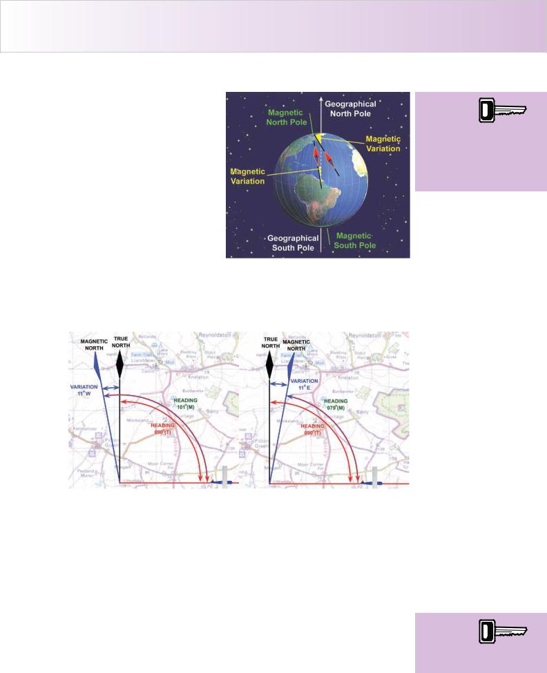
The angular difference between the locations of the magnetic and geographic poles, as measured at any given point on the Earth’s surface is called magnetic variation
(see Figure 15.20).
THE MAGNETIC COMPASS.
An instrument which is found in all aircraft, from the simplest light aircraft to the most modern glass cockpit airliner, is the simple Magnetic Compass.
A compass is an instrument designed to indicate direction on the surface of the
Earth, relative to the Earth’s magnetic poles.
In ideal conditions, the magnet at the heart of the aircraft’s Magnetic Compass, will point at all times to the Earth’s Magnetic North and South Poles. Theoretically as the aircraft changes direction the compass magnet remains aligned to the two Magnetic Poles. Because of this property of the magnet, the pilot is able to read off his aircraft’s magnetic heading from the compass. As we shall learn later in this chapter, however, there are several reasons why the compass magnet may not always lie North-South, leading to errors in compass indications.
The purpose of a magnetic compass in an aircraft, then, is to indicate heading: the direction in which the aircraft is pointing.
Magnetic influences, such as those produced by iron or steel components, electric currents etc., cause local distortions in the Earth’s magnetic field which lead to errors in the compass reading. This type of error is called compass deviation.
The rules for applying corrections for magnetic variation and deviation to the compass heading indication in order to determine an aircraft’s heading with respect to Geographical North (otherwise known as True North) are discussed later in this Chapter.
Di r e c t In d i c a t i n g Ma g n e t i c Co m p a s s .
This part of the chapter deals with the Direct Indicating, or Direct Reading Magnetic Compass, where the pilot directly reads his heading in relation to a pivoted magnet assembly.
There are two basic types of Direct Reading Magnetic Compass used in aircraft: the
Simple Magnetic Compass and, less commonly, but still found in older aircraft, the
Grid Ring Compass.
T h e Si m p l e Ma g n e t i c Co m p a s s .
The Simple Magnetic Compass - sometimes referred to as the standby compass, shown on the next page in Figure 15.18, is the direct reading compass in general use in most aircraft. The Simple Magnetic Compass is usually the main magnetic heading reference in light aircraft, and the standby compass in larger aircraft. The
237

Order: 6026
Customer: Oleg Ostapenko E-mail: ostapenko2002@yahoo.com
Customer: Oleg Ostapenko E-mail: ostapenko2002@yahoo.com
CH AP T ER 1 5 : G Y R O SCO P IC INST R U MENT S & T H E MAG NET IC CO
Simple Magnetic Compass consists of a circular compass card attached directly to a magnet assembly. This combined unit is suspended within the compass bowl.
Figure 15.18 The Simple Magnetic Compass.
A vertical lubber line on the glass window of the bowl enables the heading to be read from the compass card.
T h e G r i d R i n g Co m p a s s .
The P-type compass or Grid Ring Compass, illustrated in Figure 15.19, is found on older aircraft, such as the De Havilland Chipmunk. It is more accurate than the Simple Magnetic Compass and is more stable.
The Grid Ring Compass is, however, heavier, bulkier and more expensive. In addition it can only be read in straight and level flight, as the grid ring has to be unclamped and aligned with the North reference before a reading can be taken against the lubber line.
MAGNETIC VARIATION.
Figure 15.19 The Grid Ring Compass.
The Earth behaves as though a huge permanent magnet was situated near its centre, producing a magnetic field over its surface, as seen in Figure 15.17.
As we have said, the direction of that field at any given point can be indicated by a freely suspended magnet. Such a magnet will align itself, roughly, in a North - South direction.
However, the poles of the Earth’s magnetic field do move and are seldom coincident with the Earth’s spin axis. The position of the North Magnetic Pole is moving at about 22 nautical miles per year. Since it was first located in 1831 it has moved
238
ID: 3658
Customer: Oleg Ostapenko E-mail: ostapenko2002@yahoo.com
Customer: Oleg Ostapenko E-mail: ostapenko2002@yahoo.com
CH AP T ER 1 5 : G Y R O SCO P IC INST R U MENT S & T H E MA
approximately 625 miles. The North Magnetic Pole is presently close to Ellesmere Island in the Canadian Arctic Islands, which is 650 miles west of the Geographic North Pole. Consequently, the lines of force of the Earth’s magnetic field lie at an angle to the true meridians, and so, a freely suspended magnet will align itself as shown in Figure 15.20.
The angle, measured in the horizontal plane, between the magnetic lines of force at a given point on the Earth’s surface, and the true meridian at the same point is known as the magnetic variation. Magnetic Variation is
designated West or East depending on whether the magnetic pole lies to the West or to the East of True North, relative to the point from which the variation is measured. Magnetic Variation can have any value from zero to 180º, the latter occurring on the true meridian linking the North Geographic Pole with the North Magnetic Pole.
The angle,
measured in the horizontal
plane,
between the magnetic meridian at any point on the Earth’s surface, and the true meridian at the same point is known as magnetic variation.
Figure 15.21 Magnetic Variation West. |
Figure 15.22 Magnetic Variation East. |
When magnetic direction is the same as true direction, the variation is nil; otherwise Magnetic North direction may lie either to the West or East of True North. A simple rhyme helps in working out which way to apply variation to your heading:- “Variation West, Magnetic best, Variation East, Magnetic least”.
In Figure 15.21, an aircraft is flying due East (090º True) by reference to points on the ground, and variation is 11º West. Therefore, the pilot has had to add the magnetic variation to his planned true heading to obtain the correct magnetic heading of 101º which he must fly in order to track due East (090º True) over the ground.
Conversely, as shown in Figure 15.22, if the variation is 11º East, then the pilot must subtract the variation from his planned true heading to get the correct magnetic heading of 079º which he must fly to track 090º True over the ground. Remember: “Variation West, Magnetic Best, Variation East, Magnetic Least.”
Remember,
“variation west, magnetic
best, variation
east, magnetic least.”
239
Order: 6026
Customer: Oleg Ostapenko E-mail: ostapenko2002@yahoo.com
Customer: Oleg Ostapenko E-mail: ostapenko2002@yahoo.com
CH AP T ER 1 5 : G Y R O SCO P IC INST R U MENT S & T H E MAG NET IC CO
Is o g o n a l s .
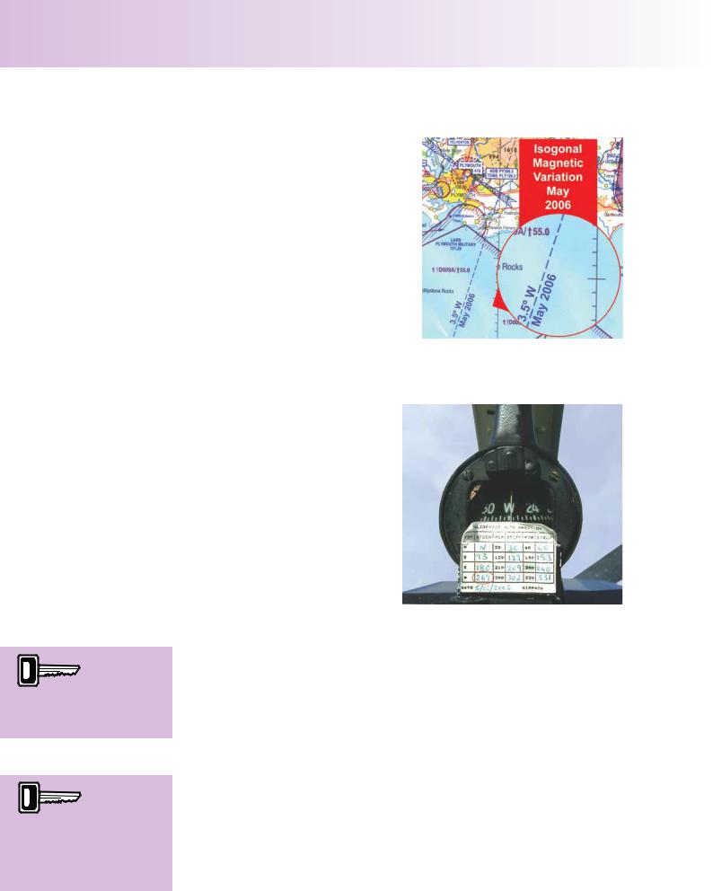
Some navigational charts are marked with lines called Isogonals. Isogonals join places on the Earth’s surface of the same magnetic variation (see Figure 15.23). You
will find Isogonals on the 1:500 000 charts.
DEVIATION. |
Figure 15.23 An Isogonal (Line of |
Constant Magnetic Variation) on a Chart. |
|
The Magnetic Compass is, of course, |
|
not only sensitive to the Earth’s |
|
magnetic field but also to the magnetic |
|
fields of electrically driven instruments |
|
and metallic objects within the cockpit. |
|
The presence of these “secondary” |
|
magnetic fields within the cockpit will |
|
cause the Magnetic Compass to deviate |
|
from pointing towards Magnetic North. |
|
The angle between the local magnetic |
|
meridian and the direction in which the |
|
compass-magnets are lying, because |
|
of secondary magnetic |
influences |
within the cockpit, is called the angle of |
|
deviation or, simply, deviation. |
Figure 15.24 Compass Deviation Card. |
|
The compass reading is
the magnetic heading
plus or minus the deviation on that particular heading.
The purpose of the
compass deviation card
is to indicate the discrepancy between the heading shown on the compass and the actual magnetic heading.
Deviation can be East or West of Magnetic North.
Deviation varies with indicated magnetic heading, so it has to be measured on a series of different headings. This is usually done by conducting a compass swing. Measured deviation is then eliminated as far as possible by making adjustments to the compass itself by means of correcting screws. Once deviation has been reduced as far as possible, the residual deviation is recorded on a compass deviation card, which is located in close proximity to the compass. During the compass swing, normal flying conditions should be simulated as far as possible, with engines running, electrical / radio services switched on, and the aircraft in a level flight attitude. It is obviously most important that no ferromagnetic objects such as tools, or watches are placed near the compass as this would introduce unknown amounts of deviation.
In Figure 15.24 the aircraft’s compass reading is 269 degrees. The compass reading is the magnetic heading plus or minus the deviation on that particular heading. The deviation card makes it easy for a pilot to fly an accurate magnetic heading. Look closely at the deviation card in Figure 15.24; the card tells the pilot that if he wishes to fly 270º Magnetic, he must steer 269º.
240
ID: 3658
Customer: Oleg Ostapenko E-mail: ostapenko2002@yahoo.com
Customer: Oleg Ostapenko E-mail: ostapenko2002@yahoo.com
CH AP T ER 1 5 : G Y R O SCO P IC INST R U MENT S & T H E MA
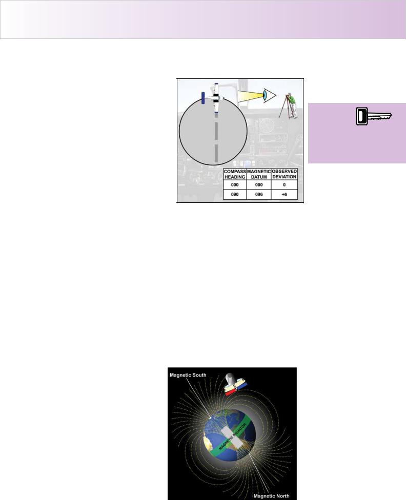
T h e Co m p a s s Sw i n g .
The basic method of determining deviation is to compare the aircraft’s compass reading with a very accurate magnetic heading obtained from the reading of a high quality ‘land’ or ‘datum’ compass (see Figure 15.25). This comparison is called a compass swing. The compass swing is carried out in an area selected specifically for this purpose. Major compass deviation errors are corrected by adjusting small magnets mounted in the aircraft’s compass system. As already explained, residual errors that remain are shown on a compass deviation card displayed in close proximity to the compass in the
cockpit, as illustrated in Figure 15.24. Figure 15.25 The Compass Swing.
There are several occasions when an aircraft might require a compass swing. Among these are:
•When compass components are installed or replaced.
•Whenever the accuracy of the compass is in doubt.
•After a maintenance inspection, if required by the schedule.
•After a significant aircraft modification, repair or replacement involving magnetic material.
•If the aircraft has been struck by lightning.
Ma g n e t i c Di p .
Except near the Earth’s ‘magnetic equator’, where the lines of force are parallel to the
Earth’s surface, one end of the freely-suspended magnet will dip below the horizontal, pointing to the nearer pole. To the North of the Magnetic Equator, the magnet’s northseeking pole will dip, as shown
in Figure 15.26, whereas to the South of the Magnetic Equator the south-seeking pole will dip.
The angle, measured in the vertical plane, between the axis of the magnet and the horizontal is called the angle of dip.
The further North or South of the Magnetic Equator a freelysuspended magnet is located, the greater will be the magnetic dip, reaching about 66º in the United Kingdom. Over the Earth’s
magnetic poles, the dip is 90º.
Figure 15.26 Magnetic Dip.
When a
compass swing is being
carried out the
aircraft’s compass reading is compared with readings from a ‘land or datum’ compass.
241
Order: 6026
Customer: Oleg Ostapenko E-mail: ostapenko2002@yahoo.com
Customer: Oleg Ostapenko E-mail: ostapenko2002@yahoo.com
CH AP T ER 1 5 : G Y R O SCO P IC INST R U MENT S & T H E MAG NET IC CO
The phenomenon
of magnetic dip is
the cause of errors in the indications of the magnetic compass when an aircraft is accelerating or turning.
The phenomenon of magnetic dip is the cause of errors in the indications of the magnetic compass when an aircraft is accelerating or turning.
COMPASS ERRORS.
Ac c e l e r a t i o n Er r o r s .
Direct reading magnetic compasses are subject to errors during linear acceleration, linear deceleration, or during a turn, which, of course, involves centrifugal acceleration.
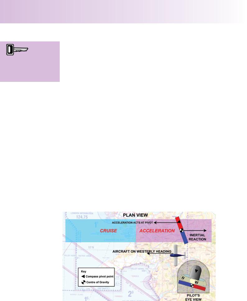
Most manoeuvres which cause the centre of gravity of a freely-suspended magnet assembly to move away from its normal position (which is almost directly below the pivot) will produce an error in the indication of a compass so as to show an apparent turn when no turn is present.
However, if the manoeuvre displaces the centre of gravity to the north or south of its usual position beneath the pivot, so that the centre of gravity and pivot are still in the plane of the magnetic meridian, the magnet assembly merely changes its northsouth tilt angle, with no rotation in azimuth, and consequently no error. There are, therefore, no linear acceleration errors in compass indications when the aircraft is on a heading of 360º or 180º. Conversely, as you might expect, linear acceleration errors are greatest when the aircraft is heading 090º or 270º.
Note, that turning and linear acceleration errors occur only where there is significant magnetic dip, so that except for a small liquid swirl effect in turns, the errors are nonexistent near the Magnetic Equator.
When dip is present, the centre of gravity of the pendulously suspended magnet is not directly under the pivot (see Figure 15.27). Therefore, when an aircraft accelerates on an Easterly or Westerly heading, the inertial reaction at the magnet’s centre of gravity causes the suspended magnet to be “left behind” giving rise to a turning moment which acts on the magnet’s centre of gravity while the acceleration lasts.
This action causes the magnet to rotate a little and indicate a turn. Once linear acceleration is complete and the aircraft is again flying at constant speed, no
Figure 15.27 Compass indicates an apparent turn towards North.
242