

На сортировку / 5 / 77724 / IIT_2
.docxNon Profit Joint Stock Company
«Almaty University of Power Engineering and Telecommunications»
Department of Electric Drive and Automation of Industrial Installations
CALCULATION GRAPHIC WORK №2
On discipline Information and Measuring Technologies
Done by: student of group EPEe-16-8
Duisembayeva T.E.
Credit book number: 164155
Checked by:senior lecturer Abdulina Z.V.
Almaty, 2017
Content
Introduction……………………………………………………………………...…3
1.Bridges of direct and alternative current..........……………………………….....4
1.1 Task 1………...…………………………………………………………...4
1.2 Task 2………...…………………………………………………………...5
1.3 Task 3………...…………………………………………………………...6
2.Self-oscillatory mode of a scanning generator…………………………………...7
2.1 Task 1……………………………………………………………………..7
2.2 Task 2……………………………………………………………………..9
2.3 Task 3………………………………...…………………………………...8
Conclusion……………………………………………………………..………….10
Reference…………………………………………………..….………..................11
Introduction
It is difficult to imagine modern systems for automatic control of production processes and telecommunications for voice, data and image transmission, which can be designed and operated without taking the measurements necessary to assess their quality and technical condition.
The main purpose of the computational and graphic work is to consolidate theoretical knowledge and acquire practical skills for measuring the parameters of electrical signals with the required accuracy. To do this, it is necessary to make the right choice of the measuring device, the measurement method for eliminating additive and multiplicative errors, to be able to use not only traditional devices (analog and digital), but also virtual, computerized complexes, for example, the LabVIEW system.
CGW No. 2 is devoted to the study of methods of measuring resistances with the help of bridges of direct and alternating currents, as well as studying the operation of the oscilloscope in various modes when measuring signal parameters.
1.1Bridges of direct and alternative currents
Task 1
In couple of wires of a multicore connection cable there was a breakdown of isolation in some point (fig. 3.1). The cable is executed from a copper wire with the section of 1,5 mm2.
It is necessary to locate damages of the line by means of the express device – Murray Bridge.

Figure 3.1 – Metallic circuit of a multicore cable
Solution:
S = 1,5 mm2 = 1,5 ∙ 10-6m2
ρ = 1,75 ∙ 10-8 Ohm∙m
L = 2km = 2∙ 103m
R1 = 85Оhm
R2 = 995Оhm
 = 23,33Оhm
 = 3,67Оhm
 = 314,6m
Task 2
The alternating-current balanced bridge is set. Parameters of three shoulders and alternating-current frequency of the power supply of the bridge are known.
It is required to determine the capacity and a loss angle of the studied C1 condenser (see the figure 2). Variants of tasks are chosen according to table 2.

Solution:
R2 = 2300 Ohm
R1 = 107.3 Ohm
C0 = 0.05 mcF
r0 = 75 Ohm
f = 400 Hz
Equilibrium condition of the bridge is
(rx + 1/jωc1) · R2 = (r0 + 1/jωc0) · R1
where rx, r0 – the active components of arms of bridge;
jωc1, jωc0 – reactive components of arms of bridge.
Then:
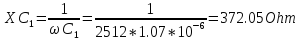
С1 = С0R2/R1; r1 = r0R1/R2;
tgδ1 = r1/XС1 = ωr1С1 = ωr0С0.


Task 3
The alternating-current balanced bridge is set (see the figure 4). Parameters of three shoulders are specified in table 3, the alternating-current frequency of the power supply is equal to f = 100 Hz and the capacity of the model condenserC0 = 0,1mcF.
It is required to define inductance and the fissile coil resistance and also its good quality. Variants of tasks are chosen according to table 3

Solution:
f = 100 Hz
C0 = 0,1mcF
R2 = 97 Ohm
R3 = 104 Ohm
r0 = 1.4 kOhm
Equilibrium of the bridge comes under a condition
Z1Z0 = R2R3
Where Z1 = r1 + jωL1;
Z0 = r0/ (1 + jωС0r0)
After transformation we will receive
r1r0 + jωL1r0 = R2R3 + jωС0r0R2R3.
Then
r1 = R2R3/r0; L1 = C0R2R3.
Quality factor off the coil
Q = ωL1/r1 = ωC0r0


Theme 2. Measurement of parameters of signals by means of EO
2.1 Self-oscillatory mode of a scanning generator
Task1
On the main input U the electronic oscilloscope (EO) has a sinusoidal voltage Uy = Umy ∙ sinωyt. The scan generator (SR) operates continuously and generates a sawtooth signal Up = at with frequency fp = 25Гц.
It is required to determine the number of images of the sinusoid of the input signal on the EO screen.
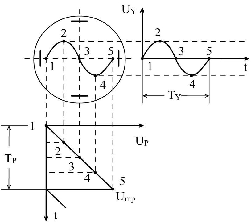
Figure 2.1 - Timing diagram of the input signal
Solution:
Umy = 5V
Ump = 10V
fy = 250 Hz
Uy=Umy∙sinωyt
ωy=2πfy =6,28∙250=1570rad/s
Uy =5 ∙ sin1570t
Tp
= =
0.04s
=
0.04s
Tp
=
 =>n = Tp
∙ fy
= 0.04∙250 =10s
=>n = Tp
∙ fy
= 0.04∙250 =10s
2.2 Frequency measurement with EO
Task 2
On an entrance of EO rectangular impulses arrive, GR works in the waiting mode. Are set: time of a delay of tz and development of Tr (see the figure 2).
It is required to determine the greatest possible duration of ti of an entrance impulse at the set GR parameters. The image of an impulse on the EO screen will be full if time of development of the horizontal line after the termination of an impulse is not less 0,1tz. Variants of tasks are chosen according to table 2.

Figure 2 – The chart of work of GR in the waiting mode
Solution:
t3=30mcs
Tp=0.3ms
tu=Tp-t3-0.1 t3=0.3
 10-3-30
 10-6-0.1
 30
30 10-6=0.273
 10-3s=0.273ms
Task 3
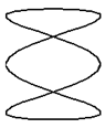
A sinusoidal signal with an unknown frequency fx is applied to the vertical input (input Y) of the electronic oscilloscope EO. On the horizontal input (input X) a signal is sent from the sample sinusoidal signal generator (SSS) with frequency fo. At some frequency ratio fх/f0 , a stationary figure of Lissajous is obtained on the screen (Table 4.3).
It is required to determine the unknown frequency fx and the measurement result. If the relative error of the frequency of the HSF is equal to δотн.
Solution:
f0 = 100Hz
δотн = 2 %
Nг = 2, Nв = 6


Conclusion
I studied the methods of measuring resistances with the help of bridges of direct and alternating currents, and also studied the work of the oscilloscope in various modes when measuring the signal parameters.
Reference
1. Афонский А.А. Измерительные приборы и массовые электронные измерения. – М.: СОЛОН-ПРЕСС, 2007. – 544 с.
2. Боридько С.И., Дементьев Н.В. Метрология и электрорадиоизмерения втелекоммуникационных системах. – М.: Горячая линия–Телеком, 2007. – 374 с.
3. Воротников С.А. Информационные устройства робототехнических систем. – М.: Изд – во МГТУ им. Н.Э. Баумана, 2005. – 384 с.
4. Назаров Н.Г. Метрология. Основные понятия и математические модели. – М.: Высшая школа, 2002.- 348 с.
5. Раннев Г.Г. Методы и средства измерения. – М.: Изд. Цент «Академия», 2006. – 336.