

Трахтенберг М.Б. / Методички / Devices / GOM-802-original
.pdfD.C. Milli-Ohm Meter
GOM-802
USER MANUAL
GW INSTEK PART NO. 82OM-80200MD1
ISO-9001 CERTIFIED MANUFACTURER
This manual contains proprietary information, which is protected by copyright. All rights are reserved. No part of this manual may be photocopied, reproduced or translated to another language without prior written consent of the Good Will company.
The information in this manual was correct at the time of printing. However, Good Will continues to improve products and reserves the right to change specifications, equipment, and maintenance procedures at any time without notice.
Good Will Instrument Co., Ltd.
No. 7-1, Jhongsing Rd., Tucheng Dist., New Taipei City 236, Taiwan.

Table of Contents
Table of Contents |
|
SAFETY INSTRUCTIONS .................................................... |
4 |
Safety Symbols .................................................... |
4 |
Safety Guidelines ................................................ |
5 |
GETTING STARTED ............................................................ |
8 |
GOM-802 Characteristics.................................... |
9 |
Key Features ...................................................... |
11 |
Front Panel Overview ........................................ |
12 |
Rear Panel Overview ......................................... |
16 |
Set Up ............................................................... |
17 |
MEASUREMENT............................................................... |
21 |
Measurement Overview .................................... |
22 |
Resistance Measurement .................................. |
23 |
Compare Function............................................. |
26 |
Temperature Measurement ............................... |
32 |
Temperature Compensation .............................. |
34 |
HANDLER/SCAN/ INTERFACE......................................... |
36 |
Handler Overview ............................................. |
37 |
Scan Overview................................................... |
38 |
Configure Interface ........................................... |
42 |
FAQ .................................................................................. |
45 |
APPENDIX........................................................................ |
46 |
Fuse Replacement ............................................. |
47 |
Temperature Measurement ............................... |
48 |
Specifications.................................................... |
51 |
Declaration of Conformity................................. |
54 |
INDEX .............................................................................. |
55 |
3
GOM-802 User Manual
SAFETY INSTRUCTIONS
This chapter contains important safety instructions that you must follow when operating the GOM-802 or when keeping it in storage. Read the following before any operation to insure your safety and to keep the GOM-802 in the best possible condition.
Safety Symbols
These safety symbols may appear in this manual or on the GOM-802.
|
|
|
|
|
|
|
|
Warning: Identifies conditions or practices that could |
|
|
|
|
|
|
|
WARNING |
result in injury or loss of life. |
|
|
|
|
|
|
|
|
|
|
|
|
|
|
|
|
|
Caution: Identifies conditions or practices that could |
|
|
|
|
|
|
|
CAUTION |
result in damage to the GOM-802 or to other properties. |
|
|
|
|
|
|
|
|
|
|
|
|
|
|
|
|
|
DANGER High Voltage |
|
|
|
|
|
|
|
|
|
|
|
|
|
|
|
|
|
Attention Refer to the Manual |
|
|
|
|
|
|
|
|
|
|
|
|
|
|
|
|
|
Protective Conductor Terminal |
|
|
|
|
|
|
|
|
|
|
|
|
|
|
|
|
|
Earth (ground) Terminal |
|
|
|
|
|
|
|
|
|
|
|
|
|
|
|
|
|
|
|
|
|
|
|
|
|
|
|
|
|
|
|
|
|
|
|
|
|
|
|
|
|
|
|
|
Do not dispose electronic equipment as unsorted |
|
|
|
|
|
|
|
|
municipal waste. Please use a separate collection facility |
|
|
|
|
|
|
|
|
or contact the supplier from which this instrument was |
|
|
|
|
|
|
|
|
purchased. |
4

SAFETY INSTRUCTIONS
Safety Guidelines
General Guideline
CAUTION
Do not place any heavy objects on the GOM-802.
Avoid severe impact or rough handling that leads to damaging the GOM-802.
Do not discharge static electricity to the GOM-802.
Use only mating connectors, not bare wires, for the terminals.
Do not disassemble the GOM-802 unless you are qualified as service personnel.
(Note) EN 61010-1:2001 specifies the measurement categories and their requirements as follows. The GOM-802 falls under category I.
Measurement category IV is for measurement performed at the source of low-voltage installation.
Measurement category III is for measurement performed in the building installation.
Measurement category II is for measurement performed on the circuits directly connected to the low voltage installation.
Measurement category I is for measurements performed on circuits not directly connected to Mains.
Power Supply AC Input voltage: 100V/ 120V/ 220V/230 V AC, 50/60Hz, 27VA, 22W
WARNING The power supply voltage should not fluctuate more than 10%.
Connect the protective grounding conductor of the AC power cord to an earth ground, to avoid electrical shock.
Fuse |
Fuse type: |
|
|
|
|
|
Line Voltage |
Rating |
Fuse |
WARNING |
|
100V |
90-110V |
T0.3A 250V |
|
|
120V |
108-132V |
T0.3A 250V |
|
|
220V |
198-242V |
T0.25A 250V |
|
|
230V |
216-250V |
T0.25A 250V |
Make sure the correct type of fuse is installed before power up.
To avoid fire, only replace the fuse with the specified type and rating.
Disconnect the power cord before fuse replacement.
Make sure the cause of a fuse blowout is fixed before fuse replacement.
5

|
|
|
GOM-802 User Manual |
|
|
|
|
|
|
|
|
|
|
|
|
|
|
|
|
|
Cleaning the |
|
Disconnect the power cord before cleaning. |
|
|
GOM-802 |
|
Use a soft cloth dampened in a solution of mild |
|
|
|
|
detergent and water. Do not spray any liquid into the |
|
|
|
|
GOM-802. |
|
|
|
|
Do not use chemicals or cleaners containing harsh |
|
|
|
|
material such as benzene, toluene, xylene, and acetone. |
|
|
Operation |
|
Location: Indoor, no direct sunlight, dust free, almost |
|
|
Environment |
|
non-conductive pollution (Note below) |
|
|
|
|
Relative Humidity: < 80% |
|
|
|
|
Altitude: < 2000m |
|
|
|
|
Temperature: 0°C to 40°C (operation) |
|
(Note) EN 61010-1:2001 specifies the pollution degrees and their requirements as follows. The GOM-802 falls under degree 2. Pollution refers to “addition of foreign matter, solid, liquid, or gaseous (ionized gases), that may produce a reduction of dielectric strength or surface resistivity”.
Pollution degree 1: No pollution or only dry, non-conductive pollution occurs. The pollution has no influence.
Pollution degree 2: Normally only non-conductive pollution occurs. Occasionally, however, a temporary conductivity caused by condensation must be expected.
Pollution degree 3: Conductive pollution occurs, or dry, non-conductive pollution occurs which becomes conductive due to condensation which is expected. In such conditions, equipment is normally protected against exposure to direct sunlight, precipitation, and full wind pressure, but neither temperature nor humidity is controlled.
Storage |
|
Location: Indoor |
Environment |
|
Temperature: −10°C to 70°C |
Disposal |
Do not dispose this instrument as unsorted municipal |
|
|
waste. Please use a separate collection facility or contact |
|
|
the supplier from which this instrument was purchased. |
|
Please make sure discarded electrical waste is properly recycled to reduce environmental impact.
6
SAFETY INSTRUCTIONS
Power cord for the United Kingdom
When using the GOM-802 in the United Kingdom, make sure the power cord meets the following safety instructions.
NOTE: This lead / appliance must only be wired by competent persons
 WARNING: THIS APPLIANCE MUST BE EARTHED
IMPORTANT: The wires in this lead are coloured in accordance with the following code:
Green/ Yellow: |
Earth |
Blue: |
Neutral |
Brown: |
Live (Phase) |
As the colours of the wires in main leads may not correspond with the coloured marking identified in your plug/appliance, proceed as follows:
The wire which is coloured Green & Yellow must be connected to the Earth terminal marked with either the letter E, the earth symbol  or coloured Green/Green & Yellow.
The wire which is coloured Blue must be connected to the terminal which is marked with the letter N or coloured Blue or Black.
The wire which is coloured Brown must be connected to the terminal marked with the letter L or P or coloured Brown or Red.
If in doubt, consult the instructions provided with the equipment or contact the supplier.
This cable/appliance should be protected by a suitably rated and approved HBC mains fuse: refer to the rating information on the equipment and/or user instructions for details. As a guide, a cable of 0.75mm2 should be protected by a 3A or 5A fuse. Larger conductors would normally require 13A types, depending on the connection method used.
Any exposed wiring from a cable, plug or connection that is engaged in a live socket is extremely hazardous. If a cable or plug is deemed hazardous, turn off the mains power and remove the cable, any fuses and fuse assemblies. All hazardous wiring must be immediately destroyed and replaced in accordance to the above standard.
7
GOM-802 User Manual
GETTING STARTED
This chapter describes the GOM-802 in a nutshell, including its main features as well as its front and rear panels. After going through the panel overview, follow the Power-up sequence before attempting to use the instrument.
Please note the information in this manual was correct at the time of printing. However as GW Instek continues to improve its products, changes can occur at any time without notice. Please see the GW Instek website for the latest information and content.
Characteristics |
GOM-802 Characteristics......................................... |
9 |
|
Key Features........................................................... |
11 |
Panel Overview |
Front Panel Overview ............................................. |
12 |
|
Rear Panel Overview .............................................. |
16 |
Setup |
Tilt Stand ............................................................... |
17 |
|
Power Up ............................................................... |
18 |
|
4 Wire Kelvin Connection....................................... |
19 |
|
Zeroing (Relative Function) ................................... |
20 |
8

GETTING STARTED
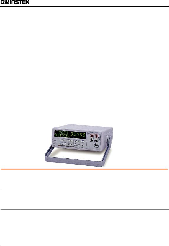
GOM-802 Characteristics
GOM-802 is a high precision programmable DC Milli-ohm meter suitable for low resistance measurements of switches, relays, connectors, PCB tracks and a variety of other devices. With the easy-to-use features, superior performance, and automatic test interfaces, the GOM-802 is a dependable instrument for resistance measurements.
Easy to Use The GOM-802 includes an easy to use comparator Features function (HI-LO-GO) that is able to easily set upper and
lower limits for pass/fail testing. The alarm buzzer can be used with the comparator function. The flexible handler interface can be used to monitor the status of the pass/fail testing.
The relative feature enables the GOM-802 to easily compensate for any stray resistance. Up to 20 different sets of HI-LO-GO settings can be stored to satisfy a number of different testing conditions. The GOM-802 is also able to recall the last test setting that was used every time it is turned on.
Performance The GOM-802 has nine selectable measurement ranges from 30mΩ to 3MΩ, a constant current source of 1uA to 1A, an accuracy of 0.05%, a 1uΩ resolution and performs measurements using four wire Kelvin connections for accurate, consistent measurements.
The ability to choose between high measurement accuracy with 7 samples/sec (full scale at 30000) or high speed measurements with 30 samples/sec (full scale at 3000) allows the GOM-802 the flexibility to fulfill a number of different measurement roles.
9

GOM-802 User Manual
Temperature
Compensation
Temperature Compensation (Optional):
The optional temperature probe (PT-100) can be used to extrapolate the resistance of a DUT at a certain temperature. When the temperature coefficient and the required temperature (of the resistance measurement) is keyed in under TC mode, the GOM-802 will display the extrapolated measurement.
Automatic |
For automatic testing The GOM-802 has a handler |
|
Testing |
interface designed for automatic testing. The handler |
|
|
interface outputs the status of PASS, FAIL, HI, LO, |
|
|
READY and EOT signals and inputs a trigger control |
|
|
signal. An RS-232 and GPIB option is also available for |
|
|
computer control applications. |
|
Applications |
|
Production testing for contact resistance of switches, |
|
|
relays, connectors, cables and printed circuit boards |
|
|
and other low resistance devices. |
|
|
Component testing of resistors, motors, fuses and |
|
|
heating elements. |
Incoming inspection and quality assurance testing.Conductivity evaluation for product design.
10