
- •Contents
- •In This Book
- •To Prepare the Multimeter for Use
- •If the Multimeter Does Not Turn On
- •To Adjust the Carrying Handle
- •To Measure Voltage
- •To Measure Resistance
- •To Measure Current
- •To Measure Frequency (or Period)
- •To Check Diodes
- •To Select a Range
- •To Set the Resolution
- •Front-Panel Display Formats
- •To Rack Mount the Multimeter
- •Front-Panel Menu Reference
- •A Front-Panel Menu Tutorial
- •Messages Displayed During Menu Use
- •Menu Example 1
- •Menu Example 2
- •Menu Example 3
- •To Turn Off the Comma Separator
- •To Make Null (Relative) Measurements
- •To Store Minimum and Maximum Readings
- •To Make dB Measurements
- •To Make dBm Measurements
- •To Trigger the Multimeter
- •To Use Reading Hold
- •To Make dcv:dcv Ratio Measurements
- •To Use Reading Memory
- •Measurement Configuration
- •Math Operations
- •Triggering
- •System-Related Operations
- •Remote Interface Configuration
- •Calibration Overview
- •Operator Maintenance
- •Power-On and Reset State
- •Command Summary
- •Simplified Programming Overview
- •Using the MEASure? Command
- •Using the CONFigure Command
- •Using the range and resolution Parameters
- •Using the READ? Command
- •Using the INITiate and FETCh? Commands
- •The MEASure? and CONFigure Commands
- •Measurement Configuration Commands
- •Math Operation Commands
- •Triggering
- •Agilent 34401A Triggering System
- •The Wait-for-Trigger State
- •Triggering Commands
- •System-Related Commands
- •The SCPI Status Model
- •What is an Event Register?
- •What is an Enable Register?
- •SCPI Status System
- •The Status Byte
- •Using *STB? to Read the Status Byte
- •To Interrupt Your Bus Controller Using SRQ
- •To Determine When a Command Sequence is Completed
- •How to Use the Message Available Bit (MAV)
- •Using *OPC to Signal When Data is in the Output Buffer
- •The Standard Event Register
- •The Questionable Data Register
- •Status Reporting Commands
- •Calibration Commands
- •RS-232 Interface Configuration
- •RS-232 Configuration Overview
- •RS-232 Data Frame Format
- •Connection to a Computer or Terminal
- •RS-232 Troubleshooting
- •RS-232 Interface Commands
- •An Introduction to the SCPI Language
- •Command Format Used in This Manual
- •Command Separators
- •Using the MIN and MAX Parameters
- •Querying Parameter Settings
- •SCPI Command Terminators
- •IEEE-488.2 Common Commands
- •SCPI Parameter Types
- •Numeric Parameters
- •Discrete Parameters
- •Boolean Parameters
- •String Parameters
- •Output Data Formats
- •Using Device Clear to Halt Measurements
- •TALK ONLY for Printers
- •To Set the GPIB Address
- •To Select the Remote Interface
- •To Set the Baud Rate
- •To Set the Parity
- •To Select the Programming Language
- •Alternate Programming Language Compatibility
- •Agilent 3478A Language Setting
- •Fluke 8840A/8842A Language Setting
- •SCPI Compliance Information
- •IEEE-488 Compliance Information
- •Execution Errors
- •Self-Test errors
- •Calibration Errors
- •Using MEASure? for a Single Measurement
- •Using CONFigure with a Math Operation
- •Using the Status Registers
- •RS-232 Operation Using QuickBASIC
- •RS-232 Operation Using Turbo C
- •Thermal EMF Errors
- •Loading Errors (dc volts)
- •Leakage Current Errors
- •Rejecting Power-Line Noise Voltages
- •Common Mode Rejection (CMR)
- •Noise Caused by Ground Loops
- •Resistance Measurements
- •4-Wire Ohms Measurements
- •Removing Test Lead Resistance Errors
- •Power Dissipation Effects
- •Settling Time Effects
- •Errors in High Resistance Measurements
- •DC Current Measurement Errors
- •True RMS AC Measurements
- •Crest Factor Errors (non-sinusoidal inputs)
- •Loading Errors (ac volts)
- •Measurements Below Full Scale
- •High-Voltage Self-Heating Errors
- •Temperature Coefficient and Overload Errors
- •Low-Level Measurement Errors
- •Common Mode Errors
- •AC Current Measurement Errors
- •Frequency and Period Measurement Errors
- •Making High-Speed DC and Resistance Measurements
- •Making High-Speed AC Measurements
- •DC Characteristics
- •AC Characteristics
- •Frequency and Period Characteristics
- •General Information
- •Product Dimensions
- •To Calculate Total Measurement Error
- •Total Measurement Error
- •Interpreting Multimeter Specifications
- •Number of Digits and Overrange
- •Sensitivity
- •Resolution
- •Accuracy
- •Transfer Accuracy
- •24-Hour Accuracy
- •90-Day and 1-Year Accuracy
- •Temperature Coefficients
- •Configuring for Highest Accuracy Measurements
- •DC Voltage, DC Current, and Resistance Measurements
- •AC Voltage and AC Current Measurements
- •Frequency and Period Measurements
- •Index

Chapter 1 Quick Start
To Set the Resolution
1
To Set the Resolution
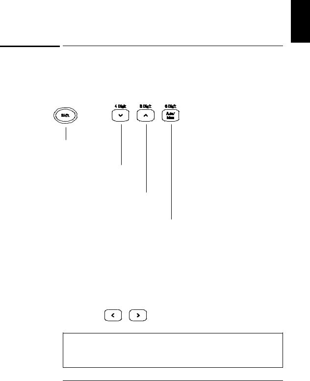
You can set the display resolution to 41⁄2, 51⁄2, or 61⁄2 digits either to optimize measurement speed or noise rejection. In this book, the most significant digit (leftmost on the display) is referred to as the “1⁄2” digit, since it can only be a “0” or “1.”
Press the Shift key.
Selects 41⁄2 digits.
Selects 51⁄2 digits.
Selects 61⁄2 digits (most noise rejection).
•The resolution is set to 51⁄2 digits at power-on and after a remote interface reset.
•The resolution is fixed at 51⁄2 digits for continuity and diode tests.
•You can also vary the number of digits displayed using the arrow keys (however, the integration time is not changed).
Fewer More
Digits Digits
Resolution is local to the selected function. This means that you can select the resolution for each function independently. The multimeter remembers the resolution when you switch between functions.
21

Chapter 1 Quick Start
Front-Panel Display Formats
-H.DDD,DDD EFFF
Front-panel display format.
5 digits
10.216,5 VDC
–Negative sign or blank (positive)
H |
1 |
” digit (0 or 1) |
“⁄2 |
DNumeric digits
EExponent ( m, k, M )
FMeasurement units ( VDC, OHM, HZ, dB )
“1⁄2” digit
This is the 10 Vdc range, 51⁄2 digits are displayed.
“1⁄2” digit
-045.23 mVDC
This is the 100 mVdc range, 41⁄2 digits are displayed.
113.325,6 OHM
This is the 100 ohm range, 61⁄2 digits are displayed.
OVL.D mVDC
This is an overload indication on the 100 mVdc range.
22

Chapter 1 Quick Start
To Rack Mount the Multimeter
1
To Rack Mount the Multimeter
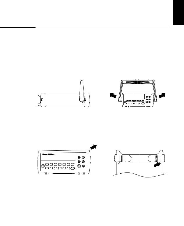
You can mount the multimeter in a standard 19-inch rack cabinet using one of three optional kits available. Instructions and mounting hardware are included with each rack-mounting kit. Any Agilent System II instrument of the same size can be rack-mounted beside the 34401A.
Remove the carrying handle, and the front and rear rubber bumpers, before rack-mounting the multimeter.
To remove the handle, rotate it to the vertical position and pull the ends outward.
Front |
Rear (bottom view) |
To remove the rubber bumper, stretch a corner and then slide it off.
23

Chapter 1 Quick Start
To Rack Mount the Multimeter
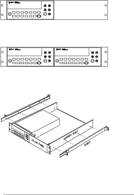
To rack mount a single instrument, order adapter kit 5063-9240.
To rack mount two instruments side-by-side, order lock-link kit 5061-9694 and flange kit 5063-9212.
To install one or two instruments in a sliding support shelf, order shelf 5063-9255, and slide kit 1494-0015 (for a single instrument, also order filler panel 5002-3999).
24

2
2
Front-Panel
Menu Operation

Front-Panel Menu Operation
By now you should be familiar with the FUNCTION and RANGE / DIGITS groups of front-panel keys. You should also understand how to make front-panel connections for the various types of measurements. If you are not familiar with this information, we recommend that you read chapter 1, “Quick Start,” starting on page 11.
This chapter introduces you to three new groups of front-panel keys: MENU, MATH, and TRIG. You will also learn how to use the comma separator and store readings in memory. This chapter does not give a detailed description of every front-panel key or menu operation. It does, however, give you a good overview of the front-panel menu and many front-panel operations. See chapter 3 “Features and Functions,” starting on page 49, for a complete discussion of the multimeter’s capabilities and operation.
26