


Chapter 1 Quick Start
To Measure Voltage
1
To Measure Voltage
Ranges: 100 mV, 1 V, 10 V, 100 V, 1000 V (750 Vac)
Maximum resolution: 100 nV (on 100 mV range)
AC technique: true RMS, ac-coupled
To Measure Resistance
Ranges: 100 Ω, 1 kΩ , 10 kΩ , 100 kΩ , 1 MΩ , 10 MΩ , 100 MΩ Maximum resolution: 100 µΩ (on 100 ohm range)
17
Chapter 1 Quick Start
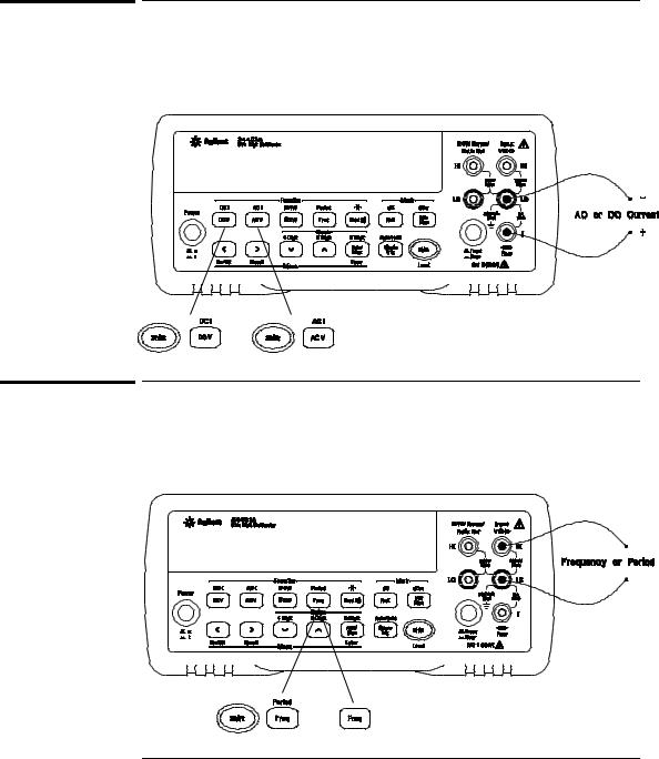
To Measure Current
To Measure Current
Ranges: 10 mA (dc only), 100 mA (dc only), 1 A , 3 A Maximum resolution: 10 nA (on 10 mA range)
AC technique: true RMS, ac-coupled
To Measure Frequency (or Period)
Measurement band: 3 Hz to 300 kHz (0.33 sec to 3.3 sec) Input signal range: 100 mVac to 750 Vac
Technique: reciprocal counting
18
Chapter 1 Quick Start
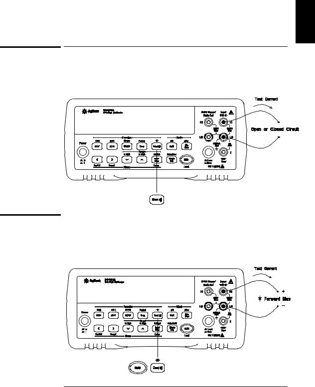
To Test Continuity
1
To Test Continuity
Test current source: 1 mA |
|
|
|
|
|
|
|
|
|
|
|
|
|
|
|
|
|
|
|
|
|
|
|
|
|
|
|
|
|||||||||||
Maximum resolution: 0.1 |
Ω |
(range is fixed at 1 kohm) |
|||||||||||||||||||||||||||||||||||||
Beeper threshold: 1 Ω to |
|
|
1000 Ω ( beeps below adjustable threshold) |
||||||||||||||||||||||||||||||||||||
|
|
|
|
|
|
|
|
|
|
|
|
|
|
|
|
|
|
|
|
|
|
|
|
|
|
|
|
|
|
|
|
|
|
|
|
|
|
|
|
|
|
|
|
|
|
|
|
|
|
|
|
|
|
|
|
|
|
|
|
|
|
|
|
|
|
|
|
|
|
|
|
|
|
|
|
|
|
|
|
|
|
|
|
|
|
|
|
|
|
|
|
|
|
|
|
|
|
|
|
|
|
|
|
|
|
|
|
|
|
|
|
|
|
|
|
|
|
|
|
|
|
|
|
|
|
|
|
|
|
|
|
|
|
|
|
|
|
|
|
|
|
|
|
|
|
|
|
|
|
|
|
|
|
|
|
|
|
|
|
|
|
|
|
|
|
|
|
|
|
|
|
|
|
|
|
|
|
|
|
|
|
|
|
|
|
|
|
|
|
|
|
|
|
|
|
|
|
|
|
|
|
|
|
|
|
|
|
|
|
|
|
|
|
|
|
|
|
|
|
|
|
|
|
|
|
|
|
|
|
|
|
|
|
|
|
|
|
|
|
|
|
|
|
|
|
|
|
|
|
|
|
|
|
|
|
|
|
|
|
|
|
|
|
|
|
|
|
|
|
|
|
|
|
|
|
|
|
|
|
|
|
|
|
|
|
|
|
|
|
|
|
|
|
|
|
|
|
|
|
|
|
|
|
|
|
|
|
|
|
|
|
|
|
|
|
|
|
|
|
|
|
|
|
|
|
|
|
|
|
|
|
|
|
|
|
|
|
|
|
|
|
|
|
|
|
|
|
|
|
|
|
|
|
|
|
|
|
|
|
|
|
|
|
|
|
|
|
|
|
|
|
|
|
|
|
|
|
|
|
|
|
|
|
|
|
|
|
|
|
|
|
|
|
|
|
|
|
|
|
|
|
|
|
|
|
|
|
|
|
|
|
|
|
|
|
|
|
|
|
|
|
|
|
|
|
|
|
|
|
|
|
|
|
|
|
|
|
|
|
|
|
|
|
|
|
|
|
|
|
|
|
|
|
|
|
|
|
|
|
|
|
|
|
|
|
|
|
|
|
|
|
|
|
|
|
|
|
|
|
|
|
|
|
|
|
|
|
|
|
|
|
|
|
|
|
|
|
|
|
|
|
|
|
|
|
|
|
|
|
|
|
|
|
|
|
|
|
|
|
|
|
|
|
|
|
|
|
|
|
|
|
|
|
|
|
|
|
|
|
|
|
|
|
|
|
|
|
|
|
|
|
|
|
|
|
|
|
|
|
|
|
|
|
|
|
|
|
|
|
|
|
|
|
|
|
|
|
|
|
|
|
|
|
|
|
|
|
|
|
|
|
|
|
|
|
|
|
|
|
To Check Diodes
Test current source: 1 mA
Maximum resolution: 100 µV range( is fixed at 1 Vdc)
Beeper threshold: 0.3 volts ≤ Vmeasured ≤ 0.8 volts (not adjustable)
19

Chapter 1 Quick Start
To Select a Range
To Select a Range
You can let the multimeter automatically select the range using autoranging or you can select a fixed range using manual ranging.
Selects a lower range and disables autoranging.
Selects a higher range and disables autoranging.
Toggles between autoranging and manual ranging.
Man annunciator is on when manual range is enabled.
•Autoranging is selected at power-on and after a remote interface reset.
•Autorange thresholds:
Down range at <10% of range
Up range at >120% of range
•If the input signal is greater than the present range can measure, the multimeter will give an overload indication (“OVLD”).
•For frequency and period measurements from the front panel, ranging applies to the signal’s input voltage, not its frequency.
• The range is fixed for continuity (1 kΩ range) and diode (1 Vdc range).
Ranging is local to the selected function. This means that you can select the ranging method (auto or manual) for each function independently. When manually ranging, the selected range is local to the function;
the multimeter remembers the range when you switch between functions.
20