

Chapter 3 Features and Functions
Operator Maintenance
Operator Maintenance
This section describes how to replace the power-line and current fuses. If you need additional information about replacing parts or repairing the multimeter, see the Service Guide.
To Replace the Power-Line Fuse
The power-line fuse is located within the multimeter’s fuse-holder assembly on the rear panel (see also page 15). See the rear panel of the multimeter for the proper fuse rating. To replace the 250 mAT fuse, order Agilent part number 2110-0817.
To Replace the Current Input Fuses
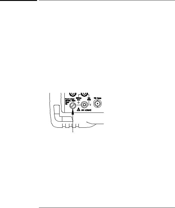
The front and rear current input terminals are protected by two series fuses. The first fuse is a 3A, 250 Vac, fast-blow fuse and is located on the rear panel. To replace this fuse, order Agilent part number 2110-0780.
With a small flatblade screwdriver, push in on the fuse cap and rotate it counterclockwise. Remove the fuse cap and fuse.
A second fuse is located inside the multimeter to provide an additional level of current protection. This fuse is a 7A, 250 Vac, high-interrupt rated fuse (Agilent part number 2110-0614). To replace this fuse, you must remove the multimeter’s case by loosening three screws. See the Service Guide for more information on disassembling the multimeter.
100

For your convenience, this table is duplicated on the rear cover of this manual and on the Quick Reference Card.
Chapter 3 Features and Functions
Power-On and Reset State
Power-On and Reset State
The parameters marked with a bullet ( • ) are stored in non-volatile memory.
The factory settings are shown.
Measurement |
Configuration |
Power-On/Reset |
State |
|
|
||||
|
AC Filter |
|
|
|
20 Hz |
(medium filter) |
|
|
|
|
Autozero |
|
|
On |
|
|
|
|
|
• |
Continuity |
Threshold |
• |
10Ω |
|
|
|
|
|
|
Function |
|
|
DC |
volts |
|
|
3 |
|
|
Input |
Resistance |
|
10 Ω |
M(fixed for all dcv ranges) |
|
|||
|
Integration Time |
|
10 PLCs |
|
|
||||
|
Range |
|
|
|
Autorange |
|
|
|
|
|
|
|
|
|
|
|
|||
|
Resolution |
|
51 2 digits, slow mode |
|
|
||||
|
|
|
|
|
⁄ |
|
|
|
|
Math Operations |
Power-On/Reset |
State |
|
|
|||||
|
Math State, Function |
|
Off, Null |
|
|
|
|||
|
Math Registers |
|
All registers are cleared |
|
|
||||
• |
dBm Reference Resistance |
• |
600Ω |
|
|
|
|
||
Triggering |
Operations |
Power-On/Reset |
State |
|
|
||||
|
Reading Hold Threshold |
|
0.10% of range |
|
|
|
|||
|
Samples Per Trigger |
|
1 sample |
|
|
|
|||
|
Trigger Delay |
|
Automatic Delay |
|
|
||||
|
Trigger Source |
|
Auto Trigger |
|
|
|
|||
System-Related Operations |
Power-On/Reset |
State |
|
|
|||||
• |
Beeper Mode |
• |
On |
|
|
|
|
||
• Comma Separators |
• |
On |
|
|
|
|
|||
|
Display Mode |
|
On |
|
|
|
|
||
|
Reading Memory |
|
Off |
(cleared) |
|
|
|||
Input/Output |
Configuration |
Power-On/Reset |
State |
|
|
||||
• |
Baud Rate |
• |
9600 baud |
|
|
|
|||
• |
GPIB Address |
• |
22 |
|
|
|
|
||
• |
Interface |
|
• GPIB (IEEE-488) |
|
|
||||
• |
Language |
|
• |
SCPI |
|
|
|
|
|
• |
Parity |
|
|
• |
Even |
(7 data |
bits) |
|
|
Calibration |
|
|
Power-On/Reset |
State |
|
|
|||
• |
Calibration |
State |
• |
Secured |
|
|
|
||
|
|
|
|
|
|
|
|
|
|
101

102

4
4
Remote Interface
Reference

Remote Interface Reference
• Command Summary, starting on page 105
 > • Simplified Programming Overview, starting on page 112
•The MEASure? and CONFigure Commands, starting on page 117
•Measurement Configuration Commands, starting on page 121
•Math Operation Commands, starting on page 124
•Triggering, starting on page 127
•Triggering Commands, starting on page 130
•System-Related Commands, starting on page 132
•The SCPI Status Model, starting on page 134
•Status Reporting Commands, starting on page 144
•Calibration Commands, on page 146
•RS-232 Interface Configuration, starting on page 148
•RS-232 Interface Commands, on page 153
> • An Introduction to the SCPI Language, starting on page 154
•Output Data Formats, on page 159
•Using Device Clear to Halt Measurements, on page 160
•TALK ONLY for Printers, on page 160
•To Set the GPIB Address, on page 161
•To Select the Remote Interface, on page 162
•To Set the Baud Rate, on page 163
•To Set the Parity, on page 164
•To Select the Programming Language, on page 165
•Alternate Programming Language Compatibility, starting on page 166
•SCPI Compliance Information, on page 168
•IEEE-488 Compliance Information, on page 169
If you are a first-time user of the SCPI language, you may want to refer to these sections to become familiar with the language before attempting to program the multimeter.
104