

Учебники / Micro- and Nanotechnology for Neurotology Zeng 2006
.pdfwhere the subscripts o and c denote the Ormia and conventional concepts shown on the left and right of figure 3, respectively. So and Sc are the sensitivities of the microphones in volts/Pascal, i = –1, c is the sound speed,is the angle of incident sound, c and o are the resonant frequencies of the conventional and ormia directional microphone, respectively,
c |
= |
k |
, |
o |
= |
kt |
, |
|
|
||||||
|
|
mc |
|
|
I |
||
and is the driving frequency.
The dimensions of the microphones are assumed to both be 1 ! 2 mm, and the structures are constructed out of 1- m-thick polysilicon. Both microphones thus have the same area s. For the Ormia microphone, the total mass, obtained from our finite element model is m = 0.975 ! 10–8 kg, the mass moment of inertia about the axis through the supports is I = 3.299 ! 10–15 kgm2. The resonant frequency of the rotational mode o is predicted to be 1409 Hz. For the conventional microphone, the mass is mc = 0.46 ! 10–8 kg, the resonant frequency of the diaphragm c is found to be about 10 kHz. The bias voltage Vb = 1 V and the distance between the diaphragm and the backplate electrode is h = 3 m. The damping constants in each design are selected to achieve critical damping, i.e. c = o = 1. The parameter is equal to 0.69. This parameter is computed by taking the inner product of the first vibrational mode shape of the clamped plate with the uniformly distributed acoustic pressure.
Predicted acoustic responses for the two microphone diaphragm designs show that the Ormia microphone has approximately 20 dB greater sensitivity of the conventional microphone over the audible frequency range [Tan et al., 2002].
Along with the acoustic sensitivity, it is also very important to examine the lowest sound levels that can be measured with a given microphone. This is limited by the self-noise of the microphone [Gabrielson, 1993]. Noise performance of microphones is usually characterized by using the A-weighted overall equivalent sound pressure due to the noise. In order to construct a fair comparison of the noise performance of candidate designs, a compensation filter is utilized so that the signals from the microphones are adjusted to have identical frequency responses. The compensation filter for each microphone signal was applied to achieve a flat frequency response from 250 Hz to 8 kHz. The noise of the microphone results from energy dissipation in the system that can be thought of as being due to equivalent dashpots that are distrib-
uted over the diaphragm surface. The microphone self, or thermal noise in dBA may be estimated from
N = 135.2 + 10 log10 Psd ,
where Psd is the white noise power spectrum due to thermal noise, Psd = 4 kbTR/s2 [Gabrielson, 1993]. kb is Boltzmann’s constant, kb = 1.38 ! 10–23 J/K, T is the absolute temperature, s is the area over which the dashpots act, R is the equivalent dashpot constant. In this comparison the value of R has been taken such that each design is critically damped so that the damping ratio is unity, i.e. c = o = 1. It is found that the predicted thermal noise floor of the conventional microphone is 40.4 dBA while that of the Ormia differential microphone is 20.8 dBA [Tan et al., 2002].
The significant reduction in thermal noise of the Ormia differential microphone results from the fact that the compliance of the diaphragm can be made to be very high. This high compliance is achieved by careful design of the pivot supports.
Our approach enables us to create almost any desired stiffness (or compliance) of the diaphragm through the proper design of the support at the pivot. The only ways to adjust the stiffness of a conventional diaphragm, being essentially a plate or membrane, are to adjust its thickness, or change its initial tension. The reduction of the diaphragm thickness introduces a host of fabrication difficulties and raises concerns over the device’s durability. The frequency response of the diaphragm will also suffer as its thickness is reduced because unwanted resonances will appear in the frequency range of interest. Because our design consists of a stiffened plate supported on a carefully designed hinge, we are able to design it so that any unwanted resonances are well above the frequencies of interest.
Current Challenges and Future Opportunities
Based on the predicted results described above, there are significant benefits to the use of a rather unconventional microphone diaphragm that would be very difficult to realize without the precision that is available through silicon microfabrication. Silicon microfabrication enables the use of novel diaphragm constructions that are likely to lead to significant performance benefits as this technology matures.
Biologically-Inspired Microphone for |
Audiol Neurotol 2006;11:86–94 |
91 |
Hearing Aids |
|
|

Fabrication Issues
In order for any promising microphone concept to have an impact on the hearing impaired, it is essential that great care be taken at the outset to ensure it ultimately can be fabricated in a cost-effective way. Silicon microfabrication has great potential to provide devices that can be manufactured using a minimum of human labor and, subsequently, low cost. The promise of low-cost devices has been a primary motivation in nearly all research on silicon microphones and it has proven an intoxicating lure for a number of microphone manufacturers. Despite these efforts, however, much more needs to be done to develop microphone designs that can be fabricated with a sufficiently high yield to make this approach cost-effec- tive.
It is widely accepted that by far the biggest challenge in fabricating microphones out of silicon (or other materials used in microfabrication) is the reduction of the influence of stress on the structural integrity and dynamic properties of the microphone diaphragm [Pedersen, 2001; Loeppert, 2001]. Unfortunately, due to the micromechanical properties of the materials, the fabrication process typically results in a significant amount of stress in the diaphragm that can be sufficient to result in fracture of a significant percentage of the devices before the fabrication is complete. In addition, the stress is strongly dependent on fine details of the fabrication process that are almost impossible to control sufficiently. Since the typical microphone diaphragm consists of a very thin plate, stress (either tensile or compressive) can have a marked influence on the dynamic response. Stress nearly always has significant detrimental effects on microphone performance.
Myriad approaches have been developed to reduce the effects of stress on silicon microphones including the use of corrugations and stress relieving supports [see for example Scheeper et al., 1994; Bergqvist and Rudolf, 1994; Zhang and Wise, 1994; Jennan, 1990; Cunningham and Bernstein, 1997; Spiering et al., 1993].
By incorporating a diaphragm as shown in figure 4 that, by design, has significant bending stiffness, in-plane stresses due to fabrication have substantially less impact. It is also important to note that the overall compliance of the diaphragm is determined by the design of the pivot supports, not the thickness or stress in the diaphragm as in conventional approaches. As a result, our design approach avoids many of the difficulties caused by stress in silicon microphones.
Performance Limitations due to Capacitive Sensing
Capacitive sensing, either through the use of a charged electret or a biased back-plate, is employed in the vast majority of miniature microphones that have sufficiently low noise and high sensitivity to be candidates for use in hearing aids. It is well known, however, that the use of capacitive sensing places significant design limitations on the microphone diaphragm that adversely impacts the electronic noise performance. In addition, due to the viscosity of air, the use of a biased electrode in close proximity to the diaphragm introduces a significant source of microphone self-noise. A major breakthrough in microphone performance may be achievable through the use of alternative sensing methods, such as optical sensing, by eliminating many of these design limitations.
To illustrate the limitations imposed on the noise performance of the read-out circuitry used in a capacitive sensing scheme, consider a simple model of a conventional (nondirectional) pressure-sensitive microphone. Suppose the buffer amplifier used to convert the change in microphone capacitance to an electronic signal has a white noise spectrum given by N volts/ Hz. If the effective sensitivity of the capacitive microphone is S volts/ Pascal then the input-referred noise will be N/S Pascals/Hz. In a conventional (nondirectional) capacitive microphone, the sensitivity may be approximated by S = VbA/ (hk) where Vb is the bias voltage, A is the area, h is the air gap between the diaphragm and the back plate, and k is the mechanical stiffness of the diaphragm. Here we have assumed that the resonant frequency of the diaphragm is beyond the highest frequency of interest. The input referred noise of the buffer amplifier then becomes N/S = Nhk/(VbA) Pascals/ Hz. Based on this result, one is tempted to reduce this noise by increasing the bias voltage, Vb, or by reducing the diaphragm stiffness, k.
Unfortunately, one is not free to adjust these parameters at will because the forces that are created by the biasing electric field can cause the diaphragm to collapse against the back plate. In a constant-voltage (as opposed to constant charge) biasing scheme, the maximum voltage that can be applied between the diaphragm and the back plate is called the collapse voltage given by
|
= |
8 |
|
kh3 |
|
V |
|
|
|
, |
|
|
|
||||
collapse |
|
27 |
|
A |
|
|
|
|
|||
where is the permittivity of the air in the gap. Diaphragms that have low equivalent mechanical stiffness, k, will thus have low collapse voltages. To avoid collapse,
92 |
Audiol Neurotol 2006;11:86–94 |
Miles/Hoy |

one must have Vb !! Vcollapse. The above equation clearly shows that the collapse voltage can be increased by in-
creasing the gap spacing, h, but this comes at the cost of reducing the microphone capacitance (and electrical sensitivity), which is inversely proportional to the nominal spacing, h. Since miniature microphones (and particularly silicon microphones) have very small diaphragm areas, A, the capacitance tends to be rather small, on the order of a pF. The small capacitance of the microphone challenges the designer of the buffer amplifier because of parasitic capacitances and the effective noise gain of the overall circuit. For these reasons, the gap, h, used in silicon microphone designs tends to be small, on the order of 5 m.
The use of a gap that is as small as 5 m introduces yet another limitation on the performance that is imposed by capacitive sensing. As the diaphragm moves in response to fluctuating acoustic pressures, the air in the narrow gap between the diaphragm and the back-plate is squeezed and forced to flow in the plane of the diaphragm. Because h is much smaller than the thickness of the viscous boundary layer (typically on the order of hundreds of m), this flow produces viscous forces that damp the diaphragm motion [Skvor, 1967; Bergqvist, 1993; Homentcovschi and Miles, 2004, 2005]. It is well known that this squeeze film damping is a primary source of thermal noise in silicon microphones [Gabrielson, 1993]. By eliminating the constraints imposed by capacitive sensing along with the constraints of conventional diaphragm design approaches, microphone designs will be able to break through significant performance barriers.
In order to decouple the design of the diaphragm’s compliance from the requirements of the sensing scheme, we are developing optical methods that do not require the use of significant bias voltages [Hall and Degertekin, 2002; Cui et al., 2006]. Preliminary calculations indicate that this sensing approach can achieve noise floors less than 20 dBA, rivaling those of large precision microphones.
Nonetheless, because silicon fabrication technology permits the creation of extremely precise and complex microstructures, it opens up a new world of possibilities in sensor design.
When a revolutionary technology arrives, its primary advantages may not be initially appreciated by designers. As an example, the earliest transistor circuits quite naturally bore a strong resemblance to vacuum tube circuits with the transistors replacing the function of the tubes. When designers learned more about the advantages of transistors, entirely new circuit topologies were created, making integrated circuits possible.
This effect has also occurred in the development of silicon accelerometers. While the initial designs resembled conventional accelerometers that were reduced in size, current silicon accelerometer designs utilize complex structures for their proof-mass and microscopic interdigitated comb fingers for capacitive sensing of the motion of the proof mass [see for example Xie et al., 2004]. These new sensor designs have evolved to take advantage of what can be accomplished with silicon microfabrication.
With very few exceptions, existing attempts to fabricate silicon microphones amount to a dramatic miniaturization of the same sorts of structures that are used in conventional microphones. They consist of a thin diaphragm supported around its perimeter, and a back plate a small distance away to permit capacitive sensing [see for example Bergqvist and Rudolf, 1995]. It is likely that the real advantages of silicon microfabrication for microphones have yet to be discovered. When they are, a revolution in microphone technology may occur.
We believe that one example of this technology ‘coming of age’ is the development of the differential microphone diaphragm we have developed. This structure takes advantage of what can be accomplished using silicon microfabrication and would be particularly difficult to realize using conventional fabrication methods.
Improvements in Fabrication Technology Will Lead to Improved Designs
While there have been numerous efforts to fabricate silicon microphones, thus far very few have led to successful commercial products. The technology of fabricating silicon sensors is still relatively immature, particularly compared to the very mature and highly successful electret microphones as currently used in hearing aids.
Acknowledgement
This work is supported by NIH grant 1R01DC005762-01A1, Bioengineering Research Partnership to RNM.
Biologically-Inspired Microphone for |
Audiol Neurotol 2006;11:86–94 |
93 |
Hearing Aids |
|
|

References
 Bergqvist J: Finite-element modeling and characterization of a silicon condenser microphone with a highly perforated backplate. Sens Actuators 1993;39:191–200.
 Bergqvist J, Rudolf F: A silicon condenser microphone using bond and etch-back technology. Sens Actuators 1994;45:115–124.
Bergqvist J, Rudolf F: Process for the manufacture of integrated capacitive transducers. United States Patent 5,404,731, 1995.
 Bilsen FA, Soede W, Berkhout AJ: Development and assessment of two fixed-array microphones for use with hearing aids. J Rehabil Res Dev 1993;30:73–81.
Cui W, Bicen B, Hall N, Jones SA, Degertekin FA, Miles RN: Optical sensing in a directional MEMS microphone inspired by the ears of the parasitoid fly, Ormia ochracea. Proc IEEE Int Conf Micro Electro Mech Sys, Istanbul, January 2006.
Cunningham B, Bernstein J, Wide Bandwidth Silicon Nitride Membrane Microphones, SPIE Micromachining and Microfabrication Process Technology III. Austin, September 29–30, 1997.
 Gabrielson T: Mechanical-thermal noise in micromachined acoustic and vibration sensors. IEEE Trans Electron Devices 1993;40:903– 909.
Gibbons C, Miles RN: Design of a Biomimetic Directional Microphone Diaphragm. Proc Int Mech Eng Congr Expo, Orlando, November 2000.
 Hall NA Degertekin FL: An integrated optical interferometric detection method for micromachined capacitive acoustic transducers. Appl Phys Lett 2002;80:3859–3861.
 Homentcovschi D, Miles RN: Modeling of viscous damping of perforated planar microstructures. Applications in acoustics. J Acoust Soc Am 2004;116:2939–2947.
 Homentcovschi D, Miles RN: Viscous damping of perforated planar micromechanical structures. Sens Actuators 2005;199:544–552.
Jennan JH: The fabrication and use of micromachined corrugated silicon diaphragms. Sens Actuators 1990;A21–A23:988–992.
Loeppert PV: Scaling issues in a submillimeter MEMS microphone (abstract). J Acoust Soc Am 2001;110:2645.
 Mason A, Oshinsky ML, Hoy RR: Hyperacute directional hearing in a microscale auditory system. Nature 2001;410:686–690.
 Miles RN, Robert R, Hoy RR: Mechanically coupled ears for directional hearing in the parasitoid fly Ormia ochracea. J Acoust Soc Am 1995; 98:3059–3070.
Miles RN, Sundermurthy S, Gibbons C, Hoy R, Robert D: Differential Microphone. United States Patent application filed August 1, 2001, serial number 09/920,664.
Miles RN, Tieu TD, Robert D, Hoy RR: A mechanical analysis of the novel ear of the parasitoid fly Ormia ochracea; in Lewis ER, et al. (eds): Proceedings: Diversity in Auditory Mechanics. Singapore, World Scientific, 1997, pp 18–24.
Pedersen M: Challenges for the commercialization of acoustic sensors using microfabrication technologies (abstract). J Acoust Soc Am 2001; 110;2646.
 Ricketts TA: Impact of noise source configuration on directional hearing aid benefit and performance. Ear Hear 2000a;21:194–205.
 Ricketts TA: Directivity quantification in hearing aids: fitting and measurement effects. Ear Hear 2000b;21:45–58.
 Robert D, Amoroso J, Hoy RR: The evolutionary convergence of hearing in a parasitoid fly and its cricket host. Science 1992;258:1135–1137.
Robert R, Miles RN, Hoy RR: Directional hearing by mechanical coupling in the parasitoid fly Ormia ochracea. J Comp Physiol 1996;98: 3059–3070.
 Robert D, Read MP, Hoy RR: The tympanal hearing organ of the parasitoid fly Ormia ochracea (Diptera, Tachinidae, Ormiini). Cell Tissue Res 1994;275:63–78.
 Scheeper PR, Olthuis W, Bergveld P: The design, fabrication, and testing of corrugated silicon nitride diaphragms. J Microelectromech Syst 1994;3:36–42.
Sessler G, West J: Electret Microphone. United States Patent 3,118,022, 1964.
Spiering VL, Bouwstra S, Fluitman JHJ: Realization of mechanical decoupling zones for pack- age-stress reduction. Sens Actuators A 1993; 37–38:800–804.
Tan L, Miles RN, Cui W, Miller RA, Su Q, Weinstein MG: Response of a Biologically Inspired MEMS Differential Microphone Diaphragm. Proc SPIE AeroSense, Orlando, 2002.
Xie H, Fedder GK, Pan Z, Frey W: Integrated Monolithic Micromachined Accelerometer. United States Patent Application Publication US 2004/0231420 A1, 2004.
Yoo K, Yeh JLA, Tien NC, Gibbons C, Su Q, Miles RN: Fabrication of biomimetic 3-D structured diaphragms. Sens Actuators A 2002;97–98: 448–456.
 Zhang Y, Wise KD: Performance of non-planar silicon diaphragms under large deflections. IEEE J Microelectromech Syst 1994;3:59–68.
94 |
Audiol Neurotol 2006;11:86–94 |
Miles/Hoy |


take advantage of the so-called tonotopic organization in the cochlea, namely, the apical part of the cochlea encodes low frequencies while the basal part encodes high frequencies. These implants, therefore, all have implemented a bank of filters to divide speech into different frequency bands, but they differ significantly in their processing strategies to extract, encode, and deliver the right features. Current CI technology can provide 22 electrodes per implant, as in the Nucleus 24 model, available from Cochlear (Cochlear, Lane Cove, Australia).
Although having flexible programmability [McDermott, 1998; Zeng, 2004], hearing enhancement devices based on digital signal processor technology are expensive, costing typically $30000 for CIs, and require relatively large and expensive microelectronic chipsets that consume large amounts of power, typically 50–750 mW for a CI. Consequently, the devices require large bodyworn battery packs and accessories to produce the electrical signals needed for the deaf to hear. Furthermore, the battery life is limited to less than a week or just a few hours in many cases, requiring frequent recharging of the devices. The use of digital signal processors introduces latency in the audio signal of up to tens of milliseconds. Since the signal must be encoded and then transmitted via a wireless connection to electronics beneath the skull, only a limited number of channels (e.g., up to 22) can be processed. The expense, inconvenience, and frequent recharging requirement of current technology means that the majority of the hearing-impaired population cannot or choose not to fully benefit from the technology [Tyler et al., 2004]. The current market penetration rate for CIs is less than about 5% [Zeng, 2004].
Apart from practical and cosmetic concerns about speech processor-based CIs, there is a concern regarding hearing quality. Most speech processor algorithms encode temporal cues about the waveform envelope to aid the patient in interpreting speech [Saunders and Kates, 1997; Loizou, 1997, 1998]. While this is effective in distinguishing the spoken word (at least for Indo-European languages in quiet conditions), it provides little help in enabling the patient to hear true musical pitch for the appreciation of music or the understanding of tonal languages [Zeng, 2004]. Recent work has indicated that such temporal-based algorithms are unlikely to succeed – the source of tone transduction is truly tonotopic in the cochlea [Oxenham et al., 2004]. Properly positioning more electrodes in the cochlea, and properly stimulating them, is the most likely means for restoring tonal sense.
An alternate approach to cochlear implants and speech coding is the ambitious goal of building an artificial co-
chlea that truly mimics the behavior of the natural cochlea. Such a device could be used for research aid for understanding cochleas (e.g., for developing mathematical models), or eventually as a front-end transducer for an electrode system.
Some progress has been made in this area already. Researchers have demonstrated the ability to build fluidfilled, 1:1 scale models of the human cochlea and have demonstrated that they respond to sound in a manner similar to the known response of the mammalian cochlea [Ohyama and Koike, 1999; Lim et al., 1999; White and Grosh, 2005]. Most recently, the team of White and Grosh [2005] demonstrated the ability to use silicon micromachining technology in order to build their cochlea model. This is significant because the batch micromachining process used to fabricate the system will allow future integration of sensing elements into the structure to economically produce low-power, micromechanical, cochlear-like sensor filters. The devices built thus far are primarily for research purposes and to aid in understanding the mechanism of the cochlea.
In this same spirit, a second type of artificial cochlea may be constructed by building a mechanical bank of resonators designed to respond in a manner similar to the cochlea. A mechanical filter bank acts in a passive way to perform sub-band filtering, reducing power requirements. Furthermore, an array of such resonators may work in parallel to produce a large number of frequency bands simultaneously, reducing latency. By controlling the shape and composition of the resonators, one may design simple to complex resonances into the system, depending on the requirements of the cochlear design. The traveling wave phenomena of the cochlea may be included by lightly coupling the resonators together. A mechanical bridge version of this was demonstrated by Haronian and MacDonald [1995]. Their design employed a large array of thin bridges micromachined in silicon with lengths that were increased exponentially. This formed an array of resonators, each with a characteristic frequency. In some cases, the spacing between bridges was small enough to couple neighboring bridges (by the viscosity of air) so that the device behaved similarly to a cochlea. In addition, the viscosity of air served to dampen the resonances so that the device exhibited low Q, a desirable feature for an artificial cochlea. Apart from a single conference paper in 1995, no other work appears to be published on this research.
Japanese researchers Tanaka et al. [1998] also demonstrated a variation of this concept by fabricating an ingenious device that they called a ‘fishbone’ resonator. Their
96 |
Audiol Neurotol 2006;11:95–103 |
Bachman/Zeng/Xu/Li |

device, fabricated from silicon, consisted of an array of mechanical beams connected to a single torsional beam at their centers, making it appear as a ‘fishbone’. The resonators in this device were coupled by the central beam making it behave as an acoustic transmission line. This construction enabled the device to mimic a cochlea. The device was not directly instrumented – the researchers used external optical instrumentation to monitor the movement of the oscillators.
A third type of artificial cochlea can be built based on electronic circuitry designed to convert an input signal into multiple outputs that mimic the cochlea. Banks of band-pass filters have been built [Loulou, 2004], as well as the so-called ‘silicon cochlea’, an electronic transmission line (filter cascade) designed to mimic the cochlear function [Kuszta, 1998]. The filter cascade model seems to hold great promise. By tapping in to the cascading series of filters one can achieve a large number of outputs that appear to closely mimic the gain, filtering and dynamic range characteristics of the cochlea [Lyon and Mead, 1988, 1998; Lyon, 1998]. Moreover, such a device has been built with 117 outputs over the range of 100 Hz to 10 kHz, 61 dB dynamic range, with small size (less than 3 ! 3 mm) and low power consumption (0.5 mW) [Sarpeshkar et al., 1998; Sarpeshkar, 1999]. This is a tremendous feat that may well signal the next generation of artificial cochleas.
Whether fluidic, mechanical or electrical, the development of a small, low-power, analog, multiresonator system that can mimic the cochlea would be a major step toward developing a completely implantable bionic ear that can provide true, quality hearing.
Micromachined Multiband Transducer
We are developing a low-power micromachined multiband transducer, small enough to be implanted in the head, which we believe could ultimately alleviate the need for a speech processor. Power requirements for a system using this technology could be much less than conventional systems, enabling it to be run by rechargeable, implanted battery system. By doing so, we may envision a fully implantable bionic ear that can restore human hearing. The microphone consists of an array of micromechanical resonators, each tuned to a different center frequency, and each instrumented to an individual amplifier. The output from the device is a number of independent channels, each carrying an electrical signal representing a particular frequency sub-band of the orig-
Inductive coil |
|
and battery |
|
Electrode driver |
|
Multiresonant |
High-density |
bionic ear |
electrode |
Fig. 1. Illustration of bionic ear concept. A multiresonant transducer receives acoustic energy and splits into frequency bands that mimic the tonotopic distribution of the cochlea. An electrode driver amplifies the signal and sends current to an implanted electrode in the cochlea.
inal acoustic signal. We have built and tested two versions of this device. One used optical readout [Xu et al., 2004], the second used capacitive readout.
An illustration of the optical microphone is shown in figure 1. It consisted of an array of suspended polymer cantilevers, each one at a different length, ranging from 2 to 7 mm. The cantilevers were rectangular cross section, 100 m in width and 40 m in height, made from epoxy using modern micromachining techniques for polymer [Xu et al., 2002]. The cantilevers were suspended over an etched cavity in silicon, allowing them freedom to vibrate. A second rectangular epoxy channel was fabricated to meet the cantilever at its distal end, stopping short of contact, leaving a 20- m air gap. A 635-nm laser was directed down the cantilevers, and the light intensity was monitored at the exit end of the second epoxy channel. The transparent polymer channels acted as excellent light pipes, so that light was efficiently guided from the laser, through the channel and cantilever, through the second channel to the photodetectors at the end. When the cantilever vibrated, the cantilever was temporarily misaligned with its mating channel reducing the efficiency of light to pass across the 20- m air gap. This was seen as a reduction in light intensity at the photodetector. In this
Micromechanical Resonator Array for an |
Audiol Neurotol 2006;11:95–103 |
97 |
Implantable Bionic Ear |
|
|

Fig. 2. a Illustration of four-channel multiresonant microphone showing cantilevers of different lengths suspended above an etched open cavity. b Scanning electron microscope image of cantilevers showing air gap between resonators and receiving light pipes.
|
–20 |
286 Hz |
|
0 |
|
|
|
|
|
|
|
|
|
|
|
|
|
|
|
|
|
|
|
|
|
|
|
||
(dBVrms) |
|
720 Hz |
(dBVrms) |
–20 |
|
|
|
|
|
|
|
|
|
|
–30 |
2868 Hz |
|
|
|
|
|
|
|
|
|
|
|||
|
|
|
|
|
|
|
|
|
|
|
||||
–40 |
6948 Hz |
–40 |
|
|
|
|
|
|
|
|
|
|
||
|
|
|
|
|
|
|
|
|
|
|
||||
|
|
|
|
|
|
|
|
|
|
|
|
|||
|
|
|
|
|
|
|
|
|
|
|
|
|
||
Response |
–50 |
|
Amplitude |
–60 |
|
|
|
|
|
|
|
|
|
|
|
|
|
|
|
|
|
|
|
|
|
|
|||
–60 |
|
–80 |
|
|
|
|
|
|
|
286 Hz |
|
|||
|
|
|
|
|
|
|
|
720 Hz |
|
|||||
|
|
|
|
|
|
|
|
|
|
|
||||
–70 |
|
–100 |
|
|
|
|
|
|
|
2868 Hz |
|
|||
|
|
|
|
|
|
|
|
|
|
|
||||
|
|
|
|
|
|
|
|
|
|
|
|
|
||
|
0.1 |
1 |
10 |
|
30 |
40 |
50 |
60 |
70 |
80 |
90 |
100 |
110 |
120 |
|
a |
Frequency (kHz) |
|
b |
|
|
|
Sound level (dB) |
|
|
|
|||
Fig. 3. Frequency response and dynamic response for multiresonant transducer. a The Q10 values of these cantilevers are 9.38, 10.11, 11.56, and 14.01 for resonant frequencies at 286, 720, 2868, and 6948 Hz, respectively. Measurements were made at 70 dB (SPL). b The polymeric cantilever array has a linear dynamic range of 80 dB for sound inputs between 35 and 115 dB (SPL). Measurements were made at each cantilever’s resonance. The fourth cantilever is not shown in the right figure because it was destroyed during handling between measurements.
manner, the movement of the cantilever, and hence, the sound energy could be monitored (fig. 2).
Several variations of the optical device were built to demonstrate different fabrication methodologies. Fabrication methods included using UV patternable high-def- inition epoxy (SU-8), performing laser machining on polymer films, and performing microinjection molding. The details of the injection molding manufacturing process which produced the results presented here, have been detailed elsewhere [Xu et al., 2004].
We tested a four-resonator device by placing it under a speaker connected to an amplified tone generator. Signal was collected from the resonators and analyzed using standard data acquisition instrumentation. Frequency response, dynamic response, and directionality were recorded. The preliminary data, shown in figure 3, are very encouraging. Cantilever response shows specific peak frequencies at 286, 720, 2868, and 6948 Hz, respectively,
well within human hearing range. Q10 values (peak frequency divided by the bandwidth 10 dB below the peak) are similar to mammalian basilar response [Robles and Ruggero, 2001]. Dynamic response is linear from 35 to 115 dB SPL. While linear response is an excellent characteristic for a microphone, for cochlear stimulation, dynamic compression may need to be performed using appropriate amplification circuitry.
We have observed similar results with cantilevers prepared for capacitive readout. In those devices, the cantilevers were coated with a thin (100-nm) layer of gold on their underside forming a capacitor between each cantilever and a ground plane directly beneath each cantilever. A bias of 45 V was placed on the cantilever making it a capacitor. Vibration of the cantilever resulted in changes in the capacitance, and thus modulated an induced current across the capacitor. The small signal was amplified by a JFET and recorded using conventional microphone
98 |
Audiol Neurotol 2006;11:95–103 |
Bachman/Zeng/Xu/Li |

Table 1. Summary of differences between optical and electronic cantilevers
Optical readout |
Electrical readout |
|
|
Low noise floor |
Noisy due to electromagnetic interference – good shielding required |
Low bias |
High bias preferred (45 V) or electret |
Moderate power requirement due to |
Low power (<1 mW) |
light coupling losses (5–10 mW) |
|
Difficult integration with electronics |
Easy integration with electronics |
Good sensitivity and dynamic range |
Good sensitivity and dynamic range |
|
|
amplifiers and instrumentation. Ultimately, the capacitor (or even electret) readout is preferred over the optical readout because it is easier to integrate with conventional electronics and consumes considerably less power. However, the electrical system is more suspect to noise and must be carefully shielded, whereas the optical system demonstrated clear signal with almost no noise. Differences between electrical and optical readout are indicated in table 1.
The multiband transducer works because the individual cantilevers have been designed to exhibit resonances at frequencies within the range of human hearing. For a simple cantilever, the natural frequency is given by
|
|
1 |
|
n2 |
|
T |
|
E |
|
fk |
|
|
k |
|
|
|
|
|
|
4 |
3 |
|
2 |
|
|
||||
|
|
|
L |
|
|
||||
where E = Young’s modulus in pascals, T = thickness in meters, L = length in meters, = density in kg/m3, and nk = 1.875, 4.694, 7.855, … (nk is mode number). When energized by acoustic energy, the cantilever will respond with maximum amplitude at the natural frequency, as given by the well-known Lorentzian formula,
|
|
|
|
|
|
|
|
A f |
|
2 |
|
|
|
|
|
|
2 |
|
|
|
2 |
||
|
|
|
|
||||
|
f f0 |
|
|
|
|
|
|
|
2 |
|
|||||
|
|
|
|
|
|||
Here, is the ‘linewidth’ or full width and half maximum. For discussion, we prefer to use the ‘quality factor’ value Q10, which is peak frequency divided by the bandwidth 10 dB below the peak, or Q10 = f0/3 . Thus, high quality factors correspond to narrow resonances. The human cochlea is also a resonator and typically responds with Q10 values under 10, relatively low quality factors [Geisler, 1998]. Second and higher order modes will also be excited, but these are typically much lower in amplitude.
Traditional micromachining materials, namely silicon, ceramics and metals, characteristically exhibit large
Young’s modulus and low damping [Petersen, 1982]. This results in large natural frequencies (for example, a silicon cantilever, 1 mm ! 5 m, resonating at about 5 kHz) and high quality factors. These are desirable qualities for fabricating mechanical resonators, such as those used in miniature accelerometers and gyroscopes, but this is not satisfactory for mimicking the response of the cochlea. If the device can be built small enough, air may be used to dampen the oscillations [e.g., Haronian and MacDonald, 1995].
Polymers have more suitable material properties, exhibiting high damping and low modulus, typically 50 times less than metal. As a result, the natural frequencies of polymer cantilevers can be designed to be in the range of a few hundred Hz to 10 kHz for microphone size under 1 cm. Polymers have certain problems, however. Polymers cannot conduct electricity, requiring the addition of a thin metal layer if electrical transduction is desired. Polymers are difficult to fabricate at the small sizes required for this transducer. Polymers may exhibit longterm plastic deformation, or may develop stress from thermal processing. Indeed, our own microfabrication efforts required a special annealing step to reduce residual stress and straighten out the resonators (for microinjection molded cantilevers). Nevertheless, many engineered polymers exist that have been demonstrated as useful in critical applications, for example, polyester and polyimide.
Because natural frequency is so directly related to length (for a cantilever) it is easy to design multiband devices of arbitrary frequency distribution. Furthermore, since the signal from each cantilever is amplified, each channel’s gain may be adjusted independently. In this manner, we can enable the design of a microphone with any arbitrary frequency range and response. We can imagine designing a transducer that can correctly compress and map electrical signals to all regions of the human cochlea.
Micromechanical Resonator Array for an |
Audiol Neurotol 2006;11:95–103 |
99 |
Implantable Bionic Ear |
|
|
100 |
|
|
|
|
1 |
|
|
|
|
|
Center frequencies |
|
|
|
|
|
Cantilever lengths |
||
10 |
|
|
|
|
|
|
|
|
|
1 |
|
|
|
|
0.1 |
|
|
|
|
Frequency(kHz) |
|
|
|
|
Relativelength |
|
|
|
|
0.1 |
|
|
|
|
|
|
|
|
|
0.01 |
|
|
|
|
0.01 |
|
|
|
|
0 |
0.25 |
0.50 |
0.75 |
1.0 |
0 |
0.25 |
0.50 |
0.75 |
1.0 |
a |
Relative distance from apex |
|
b |
Relative distance from apex |
|
||||
Fig. 4. a Tonotopic mapping of the human cochlea showing center frequency as a function of distance from the apex of the cochlea. b Relative lengths for a cantilever-based multiresonator that can reproduce natural frequencies that coincide with the center frequencies.
The mammalian cochlea has a tonotopic response to frequencies [Moore, 1997]. This relationship between center frequency and position along the basilar membrane has been mapped for several mammals and generally follows a relationship of
CF = A (10 x – k),
where CF is center frequency in kHz, x is the relative distance from the apex, k 0.85 and a 1.2 for most mammals [Greenwood, 1961, Greenwood, 1990, Robles and Ruggero, 2001]. The constant A determines the range of center frequencies (20 Hz–20 kHz in humans). This relationship indicates a logarithmic compression of frequencies at the high frequency range. A typical implantable electrode array is likely to produce electrodes at equally spaced separations, indicating that our resonator design should follow a similar compression in frequency. Cantilever resonators designed to mimic this frequency are readily fabricated using lithographic or UV cutting methods. Figure 4 shows the required cantilever lengths for electrodes destined to be placed at different regions in the cochlea. The cantilever length is given as a relative number since the physical length for a given center frequency also depends on the material and thickness of the cantilever, which can be adjusted according to design criteria.
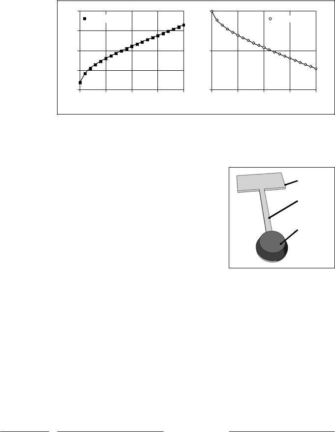
Although this discussion assumes simple straight cantilevers, one is by no means limited to designing a system of uniform cantilevers only. One can achieve complex resonance profiles by assuming more complex shapes and
Cantilever base
Cantilever arm
Patterned mass (metal)
Fig. 5. Illustration showing method for decreasing natural frequency while still maintaining short cantilever length by adding additional mass at the end of the cantilever.
mass distributions in the resonators. For example, resonators may employ torsional or meander springs, patterned mass areas, or material combinations in order to produce a desired response. For low-frequency response it would make more sense to increase the mass at the end of a cantilever rather than extend the length, enabling the transducer to remain small (fig. 5). In complex designs, the mechanical analysis is more sophisticated and finite element modeling is required. In many cases, bridge or ribbon structures may be preferred to cantilevers, particularly in the case of capacitive readout devices where
100 |
Audiol Neurotol 2006;11:95–103 |
Bachman/Zeng/Xu/Li |