
Mechanical_Intro_14.5_L09_Modal
.pdf
Lecture 9
Vibration Analysis
14.5 Release
Introduction to ANSYS Mechanical

 Chapter Overview
In this chapter free vibration as well as pre-stressed vibration analyses in Mechanical will be covered.
Chapter Contents:
A.Basics of Free Vibration
B.Geometry
C.Contact
D.Solution Setup
E.Modal Results
F.Vibration With Prestress
G.Workshop 9.1, Free Vibration – Machine Frame
2 |
© 2012 ANSYS, Inc. |
December 19, 2012 |
Release 14.5 |
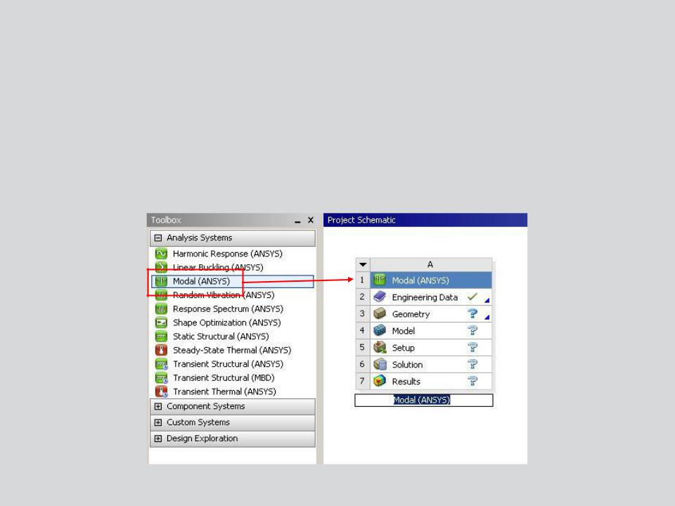
 A. Basics of Free Vibration
The free vibration analysis procedure is very similar to performing a linear static analysis, so not all steps will be covered in detail.
The schematic setup for modal (free vibration) is shown here. Later a prestressed modal setup will be covered.
3 |
© 2012 ANSYS, Inc. |
December 19, 2012 |
Release 14.5 |

 . . . Basics of Free Vibration
For a free vibration analysis, the natural circular frequencies ωi and mode |
||
shapes φi are calculated from: |
|
M φ 0 |
K ω |
2 |
|
|
|
|
|
i |
i |
Assumptions:
•[K] and [M] are constant:
–Linear elastic material behavior is assumed
–Small deflection theory is used, and no nonlinearities included
–[C] is not present, so damping is not included
–{F} is not present, so no excitation of the structure is assumed
–The structure can be constrained or unconstrained
•Mode shapes {φ} are relative values, not absolute
4 |
© 2012 ANSYS, Inc. |
December 19, 2012 |
Release 14.5 |

 B. Geometry
Modal analysis can employ any type of geometry:
•Solid bodies, surface bodies and line bodies.
•The Point Mass feature can be used:
–A point mass adds mass without additional flexibility to the structure thus reducing the natural frequency (K/M).
•Material properties: Young’s Modulus, Poisson’s Ratio, and Density are required.
Structural and thermal loads are not available in free vibration:
•If no supports (or partial) are present, rigid-body modes will occur at or near 0 Hz.
•The choice of boundary conditions will affect the mode shapes and frequencies of the part. Carefully consider how the model is constrained.
5 |
© 2012 ANSYS, Inc. |
December 19, 2012 |
Release 14.5 |

 C. Contact
Contact regions are available in free vibration analyses however contact behavior will differ for the nonlinear contact types:
Contact Type |
|
Modal Analysis |
|
|
Initially Touching |
Inside Pinball Region |
Outside Pinball Region |
||
|
||||
Bonded |
Bonded |
Bonded |
Free |
|
No Separation |
No Separation |
No Separation |
Free |
|
Rough |
Bonded |
|
Free |
|
Free |
||||
Frictionless |
No Separation |
Free |
Free |
|
Frictional |
Bonded |
Free |
Free |
|
|
|
|
|
All contact will behave as bonded or no separation in a modal analysis:
•If a gap is present:
–Nonlinear contacts will be free (no contact).
–Bonded and no separation contact will depend on the pinball size.
6 |
© 2012 ANSYS, Inc. |
December 19, 2012 |
Release 14.5 |
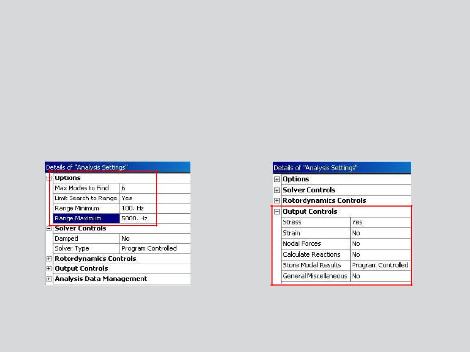
 D. Solution Setup
Within Mechanical Analysis Settings:
•Specify the number of modes to find (default is 6).
•Optionally specify a frequency search range (defaults from 0Hz to 1e+08Hz).
– Note: damped modal analysis is covered in the dynamics course.
•Request additional result output if desired.
7 |
© 2012 ANSYS, Inc. |
December 19, 2012 |
Release 14.5 |
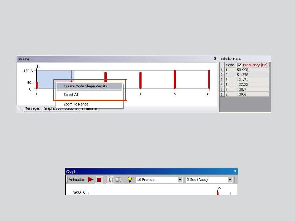
 … Solution Setup
When a solution is complete, the solution branch will display a bar chart and table listing frequencies and mode numbers.
RMB to request the modes to be displayed (or select all).
Individual mode shapes can be animated.
8 |
© 2012 ANSYS, Inc. |
December 19, 2012 |
Release 14.5 |
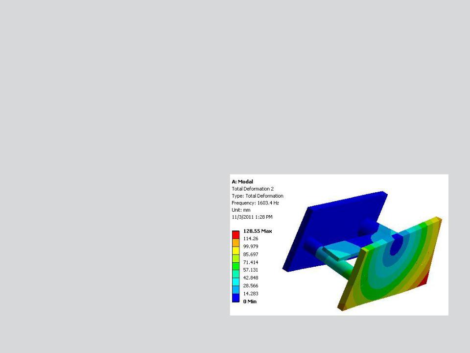
 E. Modal Results
Modal Results:
•Because there is no excitation applied to the structure the mode shapes are relative values not actual ones.
•Mode shape results are mass normalized.
– The same is true for other results (stress, strain, etc.).
Because a modal result is based on the model’s properties and not a particular input, we can interpretwhere the maximum or minimum results will occur for a particular mode shape but not the actual value.
9 |
© 2012 ANSYS, Inc. |
December 19, 2012 |
Release 14.5 |
 F. Vibration with Pre-Stress
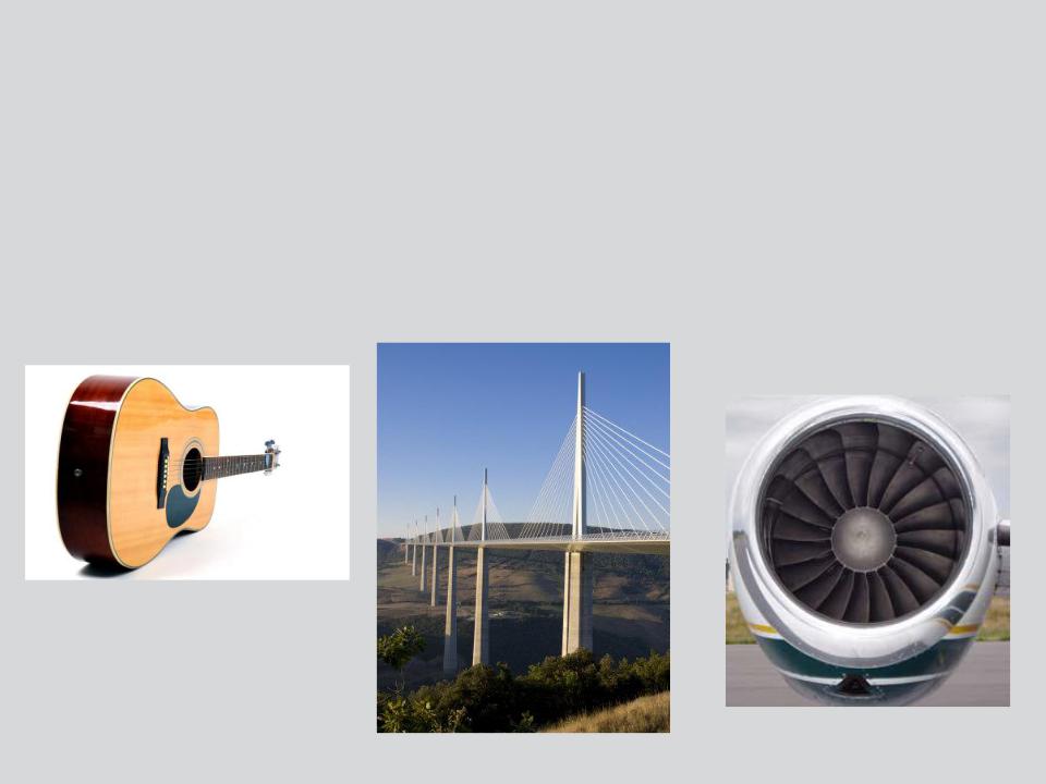
While many prestressed modal examples appear in musical instruments (guitar strings, drum heads, etc.), there are numerous engineering applications where the inclusion of prestress effects are critical.
Note: while prestressing in tension will cause frequencies to increase, compressive states can decrease natural frequencies.
10 |
© 2012 ANSYS, Inc. |
December 19, 2012 |
Release 14.5 |
