
Mechanical_Intro_14.5_L12_CAD
.pdf
Lecture 12
CAD and Parameters
14.5 Release
Introduction to ANSYS Mechanical

 Chapter Overview
In this chapter, interoperability with CAD software as well as parameters will be discussed.
A.
B.
C.
D.
E.
CAD Import
Defining Parameters in Workbench
Using the Parameter Workspace
Updating CAD Parameters
Workshop 12.1 – Parameter Management
Some CAD functionality are specific to certain CAD software, so these will be designated accordingly.
•Not all CAD software have the same features so there are some differences in CAD-related functionality which is supported in Mechanical.
2 |
© 2012 ANSYS, Inc. |
December 19, 2012 |
Release 14.5 |

 A. CAD Import
Numerous Geometry Interfaces are available for commercial CAD systems:
•For the latest information on CAD geometry interfaces and supported platforms see the ANSYS Workbench Mechanical documentation.
Geometry Interface licenses can be run in reader mode for all licenses.
Geometry Interfaces can be run in plug-in mode for the CAD software listed under
“Associative”.
DesignModeler is the Workbench geometry application and supports all the functions and capabilities listed for commercial CAD systems.
• Note the SpaceClaim Direct modeler also supports these features.
Please note, not all import capabilities described here are available with all CAD systems.
Features depend on CAD capabilities and the support provided through the CAD vendor’s
API.
3 |
© 2012 ANSYS, Inc. |
December 19, 2012 |
Release 14.5 |
 … CAD Import
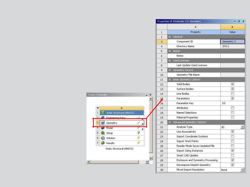
Workbench geometry properties control the import of numerous CAD items in addition to geometry:
•Parameters, Coordinate Systems, Material properties, etc.
To display geometry import properties:
•RMB > Properties, or
•View > Properties.
4 |
© 2012 ANSYS, Inc. |
December 19, 2012 |
Release 14.5 |
 … CAD Import
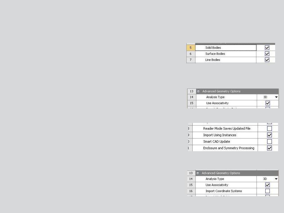
Import solid, surface, or line bodies:
•
•
•
Assemblies with mixed solids and surfaces are OK. Select desired geometry type to filter import. Cannot import a part with mixed solids and surfaces.
Use Associativity:
•Allows updating CAD geometry in Mechanical without redefining material properties, loads, supports, etc..
Smart CAD Update:
•only modified components of a CAD assembly are updated.
Local Coordinate systems:
•Allows local CS from CAD models to import with geometry. See current documentation for CAD system support.
5 |
© 2012 ANSYS, Inc. |
December 19, 2012 |
Release 14.5 |
 … CAD Import
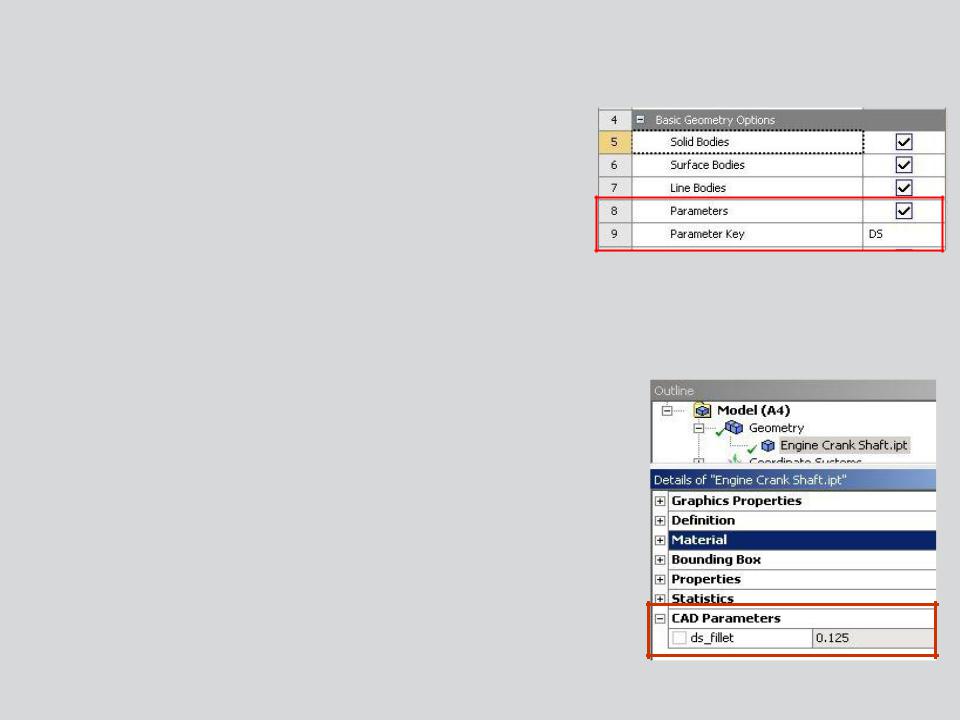
Parametric CAD dimensions can be imported into Mechanical.
• Check Parameters:
–The “Parameter Key” provides a filter. When used, only parameters whose names contain the key will be imported (default is “DS”).
–To import all CAD parameters leave the parameter key field blank.
CAD parameters will appear in the Details view for the part.
6 |
© 2012 ANSYS, Inc. |
December 19, 2012 |
Release 14.5 |
 … CAD Import
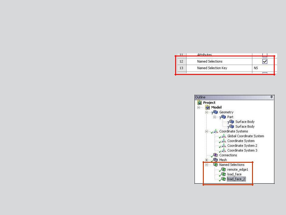
Groups defined in CAD systems can be imported as Named Selections.
Check the “Named Selections” box:
•The Named Selection key provides a filter. When used only groups containing the specified prefix in their name will be imported (default is “NS”).
–Note, multiple filters can be used by separating each with “;” (e.g. NS; AB; VR).
•To import all groups leave the named selection key field blank.
•Imported Named Selections appear in the tree.
7 |
© 2012 ANSYS, Inc. |
December 19, 2012 |
Release 14.5 |
 … CAD Import
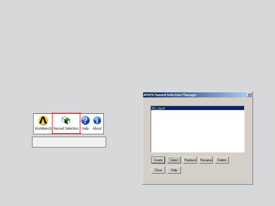
For most CAD systems Workbench offers an alternate way of working with groups of geometry via the Named Selection Manager in the CAD system.
•Access the NS Manager from the ANSYS menu within the CAD system.
•Once opened the NS Manager allows groups to be created independent of the internal CAD groups. Create, Select, Delete, etc. operations
Sample menu from CAD
8 |
© 2012 ANSYS, Inc. |
December 19, 2012 |
Release 14.5 |
 … CAD Import
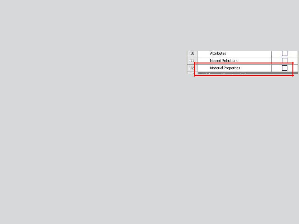
Material Properties assigned in a CAD system can be imported to Workbench (Engineering Data).
Check “Material Properties”:
•Materials imported from CAD will appear in
“Engineering Data”
•Material assignments will match the CAD material assignments.
9 |
© 2012 ANSYS, Inc. |
December 19, 2012 |
Release 14.5 |
 B. Defining Parameters in Workbench
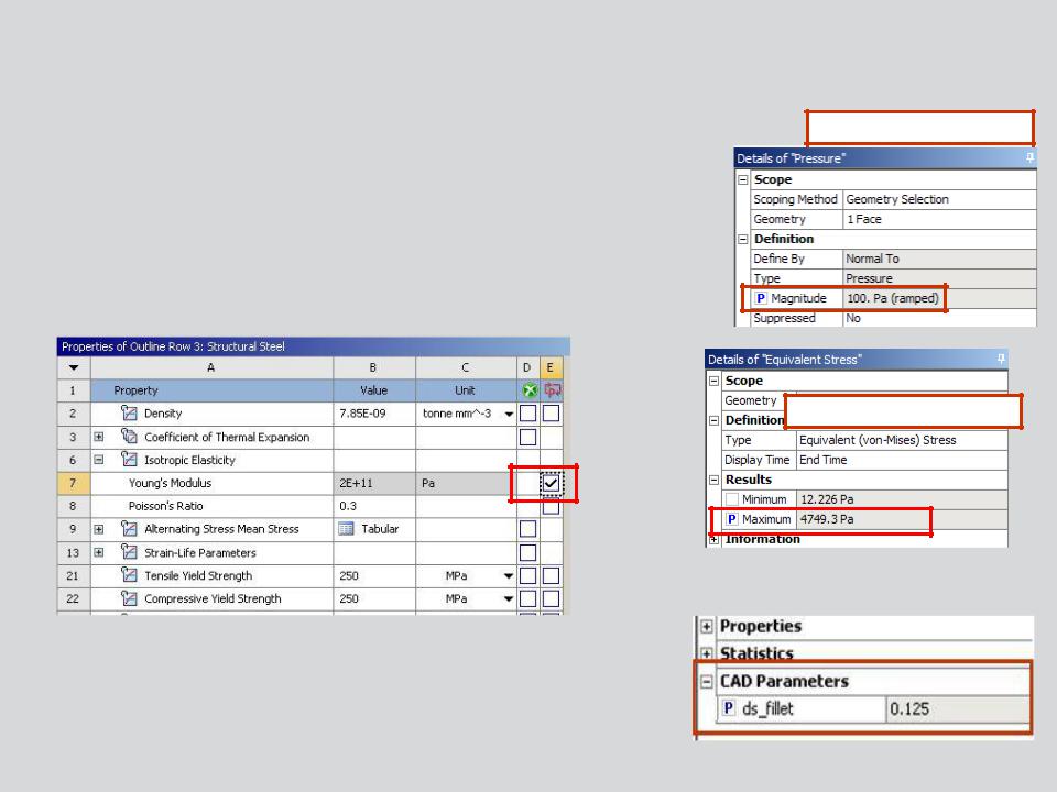
Parameters are defined in Mechanical by toggling the parameter flag on/off.
•Click in the square and a blue “P” will appear.
•Material properties are parameterized in the engineering data application.
Example of input parameters
Example of output parameters
CAD parameters must be flagged as well to allow access in Workbench (otherwise they are read only).
10 |
© 2012 ANSYS, Inc. |
December 19, 2012 |
Release 14.5 |
