

Biblio5
.pdf564 REVIEW OF FUNDAMENTALS OF ELECTRICITY WITH TELECOMMUNICATION APPLICATIONS
Figure A.1 A water circulating system.
1 ampere is the flow of 6.24 × 10¹⁸ electrons per second past a given point in a conductor. Where the flow of electrons is continuous in one direction is called direct current (dc). The currents of electrons may also periodically reverse their flow. This is called alternating current (ac). Our discussion starts with the traditional laws of direct current. Later we briefly discuss some basic principles of alternating currents.
A.2.1 Electromotive Force (EMF) and Voltage
We require a source of “electric pressure,” called electromotive force (emf), to establish a flow electrical current. The standard analogy is to use water and its flow through a water circulating system. This is illustrated in Figure A.1. The figure shows the water pressure source as a pump, two different diameter pipes, and some sort of mechanism to measure water flow. Flow can be measured in several ways such as liters or gallons per second or minute. The pump creates a difference in pressure between points x and y. Some will say that the pump sets up a “head of pressure.” This will cause water to flow from point x at the output of the pump up the large diameter pipe, across the small diameter pipe, and down through another large diameter pipe in which we installed a flow pressure gauge. The water returns to the low pressure side of the pump, shown as y in the drawing. The amount of water that will flow (i.e., analogy to amperage) depends on the difference in pressure between points x and y and the size of the small pipe. The difference in pressure is analogous to electromotive force.
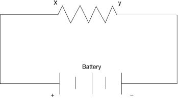
Figure A.2 is an electrical representation of the circulating water system shown in Figure A.1. The battery (see Section 2.3.1) supplies the electrical pressure or emf. It causes the electricity to flow from the high potential side of the battery, labeled x, to its low potential side, labeled y in Figure A.2. The amount of current that will flow will depend upon the emf and the nature of the resistor, shown between points x and y.
The difference of water pressure may be measured in units such as “difference in head in feet.” The emf of the electric circuit, on the other hand, is measured in terms of a unit called a volt.
Another important term is electric potential. In Figure A.2 we can say that the electric
A.3 OHM’S LAW |
565 |
Figure A.2 A simple electric circuit.
potential at the positive terminal of the battery is higher than that of its negative terminal. The difference is the electromotive force of the battery or other source. The potential at point y will be lower than the potential at point x. Thus we say that there is a potential between x and y. The potential drop is measured in volts and the magnitude of the drop depends on the resistance of the conductors and the resistor.
A.2.2 Resistance
In Figure A.1, there is no practical unit to measure the “resistance” of the piping system. If the small pipe diameter is yet made smaller, the flow of water will decrease. This pipe resistance, that which reduces the water flow, is analogous to the electrical resistance of Figure A.2. The unit of electrical resistance is well defined and is called the ohm.
To review these electrical units:
•The flow of current in a conductors is measured in amperes (A).
•The resistance to this flow is called the ohm (Q ).
•The electrical pressure, called the emf, is measured in volts (V).
A.3 OHM’S LAW
The product of the current (amperes) and resistance (ohms) of an electrical circuit is equal to the voltage (volts). Note how we have carefully stated the units of measure. The law can be stated mathematically by
E c IR, |
(A.1) |
where E is the voltage and derives from “emf,” I is the current, and R is the resistance. Ohm’s law can be stated in other ways by simple algebraic translation of terms. For example:
I c E/ R, |
(A.2) |
R c E/ I. |
(A.3) |
A.3 OHM’S LAW |
567 |
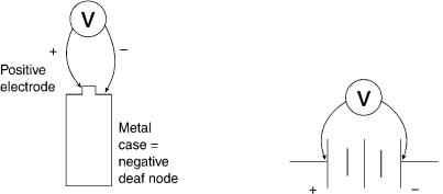
Figure A.4 Measuring the voltage of a battery: (a) a typical dry cell; (b) Showing voltage measurement using the standard battery drawing symbol. These are open circuit measurements.
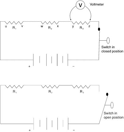
Emf is measured with a voltmeter, as shown in Figure A.4, where the open circuit voltage (emf) of a battery is measured. A voltmeter is also used to measure potential drop as shown in Figure A.3a. Here the voltmeter is connected across R3 (across points y and z). In later discussion we will also call this the IR drop. Remember Ohm’s law: E c IR. Regarding the potential drop across R3, if we know the resistance of R3 and we know the current passing through it, we know the potential or IR drop. This is one of the many applications of Ohm’s law.
In Figure A.3a, if we measure the potential drop (IR drop) in volts across each resistance and sum the values, this will equal the value of the battery emf in the closed circuit condition.
Example of Series Resistances. Four resistors are connected in series. Their resistance values are 250, 375, 136, and 741 Q . Suppose we were to replace these four with just one resistor. The current through the circuit will be the same for one or for the four resistors in series. What will be the value in ohms of the single replacement resistor?
We know that this resistor must have a value equal to the four of these resistors if there is no change in current. Just sum the resistor values or 250 + 375 + 136 + 741 c 1502 Q . The rule here is that when we want to calculate the equivalent resistance of resistors in series, we just sum the resistances of each resistor.
A.3.2 Resistance of Conductors
The current we can expect through a conductor with a fixed emf source varies directly with (1) the resistivity3 of the type of conductor, (2) the length of the conductor, and (3) and inversely with its cross-sectional area, a function of its diameter. Unless otherwise specified, all conductors that we will discuss are copper.
Outside plant engineers are faced with the design of the subscriber loop (Section 5.4). This is a wire pair extending from the local serving exchange to the telephone instrument (subset) on the subscriber’s premises. A major design constraint is the resistance of the subscriber loop. At some point as the loop is extended in length, there will be so much resistance that its signaling capability is lost. One way we can extend the length and maintain the signaling capability is to increase the wire diameter.
In mainland Europe, wire diameter is given in millimeters. In North America a copper
3Resistivity is a unit constant used to determine the conductive properties of a material.

568 REVIEW OF FUNDAMENTALS OF ELECTRICITY WITH TELECOMMUNICATION APPLICATIONS
Table A.1 American Wire Gauge (AWG) versus Wire Diameter and
Resistance
American |
Diameter |
Resistance (Q / km)a |
Wire Gauge |
(mm) |
at 208C |
|
|
|
11 |
2.305 |
4.134 |
12 |
2.053 |
5.210 |
13 |
1.828 |
6.571 |
14 |
1.628 |
8.284 |
15 |
1.450 |
10.45 |
16 |
1.291 |
13.18 |
17 |
1.150 |
16.61 |
18 |
1.024 |
20.95 |
19 |
0.9116 |
26.39 |
20 |
0.8118 |
33.30 |
21 |
0.7229 |
41.99 |
22 |
0.6439 |
52.95 |
23 |
0.5733 |
66.80 |
24 |
0.5105 |
84.22 |
25 |
0.4547 |
106.20 |
26 |
0.4049 |
133.9 |
27 |
0.3607 |
168.9 |
28 |
0.3211 |
212.9 |
29 |
0.2859 |
268.6 |
30 |
0.2547 |
338.6 |
31 |
0.2268 |
426.8 |
32 |
0.2019 |
538.4 |
a These figures must be doubled for loop/ km. Remember it has a “go” and “return” path.
wire’s diameter is indicated by its gauge. Here we mean American Wire Gauge (AWG), formerly known as Brown & Sharpe (B&S). Table A.1 compares common AWG values with copper wire diameter in mm and the resistance in ohms per kilometer (Q / km).
A.4 RESISTANCES IN SERIES AND IN PARALLEL, AND KIRCHHOFF’S LAWS
As previously discussed, the total resistance of series resistors is equal to the sum of the individual resistances. If we refer to Figure A.3, the total resistance, RT is:
RT c R1 + R2 + R3. |
(A.4) |
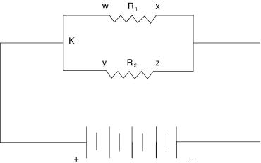
Resistances in parallel are another matter. Consider Figure A.5. Here the current in the circuit divides and each resistor carries its share. Now apply Ohm’s law and we find that the current across each resistor must be equal to the potential measured across the particular resistor divided by its value in ohms. In this particular circuit (Figure A.5), the potential across either resistor is equal to the emf supplied by the battery. In reality the battery is supplying two currents, one through resistor w-x and the second through y-z. For any circuit having two resistors in parallel, the current supplied to the combination must be greater than the current supplied to either branch. It follows, then, that we could replace these two resistors with a single resistor in series with the emf supply, and the value of that resistor must be less than the ohmic value of either single resistor in parallel.
A.4 RESISTANCES IN SERIES AND IN PARALLEL, AND KIRCHHOFF’S LAWS |
569 |
Figure A.5 Model of a circuit with two resistances in parallel and a battery as the emf source.
A.4.1 Kirchhoff’s First Law
The first law states that at any point in an electrical circuit there is as much current flowing to the point as away from it. The laws applies no matter how many branches there are in the circuit. Figure A.5 shows point K in the circuit. Let I be the current being supplied by the battery emf source to the combination of the two resistors in parallel; I1 and I2 are the currents through the two resistors, respectively. We now can say, based on Kirchhoff’s first law, that:
I c I1 + I2. |
(A.5) |
Again consider the circuit in Figure A.5. Let R be the equivalent resistance of the two resistors in parallel. Applying Ohm’s law:
R c E/ I. |
|
Substitute Eq. (A.5). We then have: |
|
R c E/ (I1 + I2). |
(A.6) |
However, I1 c E/ R1 and I2 c E/ R2. As a consequence: |
|
R c E/ [(E/ R1) + (E/ R2)]. |
(A.7) |
Divide Eq. (A.7) through by E and we now have: |
|
R c 1/ [(1/ R1) + (1/ R2)]. |
(A.8) |
Simplify the compound fraction and we have: |
|
R c R1 × R2/ (R1 + R2). |
(A.9) |
570 REVIEW OF FUNDAMENTALS OF ELECTRICITY WITH TELECOMMUNICATION APPLICATIONS
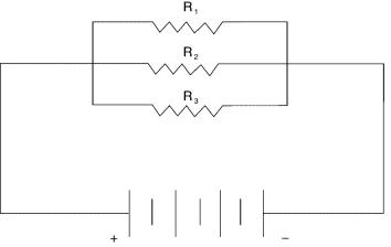
Figure A.6 Model of a circuit with three resistors in parallel.
Example. There are two resistors connected in parallel. Their values are 500 Q and 700 Q , respectively. What is the value of the equivalent combined resistance? Use Eq. (A.9).
R c 500 × 700(500 + 700) c 350, 000/ (500 + 700) c 350, 000/ 1200 c 291.6 Q .
One self-check for resistances in parallel is that the equivalent combined resistance must be smaller than the value of either resistor.
Figure A.6 shows a group of three resistors in parallel with an emf source that is a battery. We encourage the use of a short-cut when there are more than two resistors in parallel. We introduce a new term, conductance. Conductance, G, is the inverse of resistance; stated in an equation:
R c 1/ G. |
(A.10) |
The unit of conductance is the mho, which the reader will note is “ohm” spelled backwards. To solve the equivalent total resistance problem of Figure A.6, convert each resistance into its equivalent conductance, sum the values, and invert the sum.
Example. The values of the resistances in Figure A.6 are 2000, 2500, and 3000 Q ; the closed circuit emf of the battery is 24 V. What is the value of the current flowing out of the battery? Use Eq. (A.10) and convert each resistance value to its equivalent conductance and sum:
G c G1 + G2 + G3
c 1/ 2000 + 1/ 2500 + 1/ 3000 c 0.0005 + 0.0004 + 0.00033
c 0.00123 mhos |
(A.11) |
Use the inverse of Eq. (A.11) or R c 1/ G; then
A.4 RESISTANCES IN SERIES AND IN PARALLEL, AND KIRCHHOFF’S LAWS |
571 |
R c 1/ 0.00123 c 813 Q .
We know the voltage source is 24 V and the circuit resistance is 813 Q . We now can
apply Ohm’s law to calculate the current flowing out of the battery. Use Eq. (A.2) or I c E/ R
I c 24/ 813 c 0.0295 A or 29.5 mA.
A.4.2 Kirchhoff’s Second Law
When current flows through a resistor, there is always a difference in potential when measured across the resistor (i.e., between one end and the other of the resistor). The value in volts of the difference in potential varies with the current flowing through the resistor and the resistance. In fact, as mentioned, the value is the product of the resistance (in ohms) and current (in amperes). This is just the statement of Ohm’s law, Eq. (A.1) (E c IR). In our previous discussion, it was called potential difference, voltage drop, or IR drop. This IR drop acts in the opposite direction to, or opposes, the emf which drives the current through the resistor.
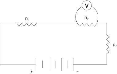
Figure A.7 is a model of a circuit with three resistors in series and a battery emf source. For reference, a voltmeter is shown measuring the voltage (the IR drop) across resistor R2. In such a closed circuit, the sum of the IR drops across the three resistors must be equal to the impressed emf. Let the IR drop across each resistor in Figure A.7 be represented by V1, V2, and V3, respectively. This, then, is how we state Kirchhoff’s second law:
E c V1 + V2 + V3, |
(A.12) |
where E is the impressed emf or closed circuit battery voltage. In the case of Figure A.7, we can write:
E c IR1 + IR2 + IR3. |
(A.13) |
Figure A.7 A model circuit for three resistors in series. A voltmeter measures the IR drop across resistor R2.
572 REVIEW OF FUNDAMENTALS OF ELECTRICITY WITH TELECOMMUNICATION APPLICATIONS
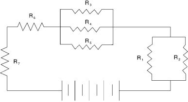
Figure A.8 A model for a circuit with series and parallel resistances with a battery as an emf source.
This equation can be restated as
E − IR1 − IR2 − IR3 c 0.
A.4.3 Hints on Solving dc Network Problems
Make a network drawing, much like we have in Figures A.1 through A.7. Then assign letters to all unknown values. This should be followed by arrows showing the direction of current flow. With the practical application of Kirchhoff’s laws, use correct algebraic signs. There should be one sign (+ or −) given to the electromotive force in the direction of the current flow, and the opposite sign is then given to the IR drops. Often we accept the clockwise direction as positive, and the counterclockwise as negative. For instance, all emfs are labeled positive that tend to make the current flow in the positive direction; and all potential drops are labeled negative, due to this flow of current as well as any emfs tending to make current flow in the opposite direction. When carrying out this exercise, we may find a solution to an equation may be preceded by a minus sign. This merely means that the actual direction of flow of current is opposite to the direction we assumed.
Example Calculation of a Series-Parallel Circuit. Figure A.8 is a model series-par- allel circuit. In other words, the circuit has a mix of resistances in series and in parallel. Hint: Replace all parallel resistors by their equivalent value first. Thus we end up with a circuit entirely of resistances in series. In other words, first calculate the equivalent resistance for resistors R1 and R2; then for R3, R4, and R5. We end up with four resistors in series: the first and second group of parallel resistors, the R6, and R7. The total resistance of the circuit is then the sum of these four resistances. Assign the following values to these resistances: R1 c 800 Q ; R2 c 1200 Q ; R3 c 3000 Q ; R4 c 5000 Q ; R5
c 4000 Q ; R6 c 600 Q ; and R7 c 900 Q .
For the first group of parallel resistances we use formula (A.9):
R c 800 × 1200/ (800 + 1200) c 960, 000/ 2000 c 480 Q .
For the second group of parallel resistances use formulas (A.10) and (A.11), as follows:
What is the current flowing out of the 48 V battery?
A.5 ELECTRIC POWER IN dc CIRCUITS |
573 |
G3 c 1/ 3000 c 0.000333; G4 c 1/ 5000 c 0.0002; G5 c 1/ 4000 c 0.00025.
Sum these values using Eq. (A.11) and
G c 0.000333 + 0.0002 + 0.00025
c 0.000783.
Use formula (A.10) to obtain the equivalent resistance
R c 1/ G c 1/ 0.000783
c 1277.14Q .
Calculate the total resistance of the circuit with the four resistances, which includes the derived resistances. Use formula (A.4):
RT c 480 + 1277.14 + 600 + 900 (Q )
c 3257.14 Q .
To calculate the current flowing out of the battery, use Ohm’s law (Eq. (A.2)):
I c E/ R c 48/ 3257.14 c 0.0147 A or 14.7 mA.
A.5 ELECTRIC POWER IN dc CIRCUITS
Batteries store chemical energy. When the battery terminals are connected to supply emf to an electric circuit, the battery chemical energy is converted to electrical energy. This manifests itself as power (work per unit time). The unit of power is the watt (W). When we pay our electric bill, we pay for kilowatt-hours of expended electric power.
The resistors in Figures A.2–A.8 dissipate power in the form of heat. In fact, not only are resistors rated for their resistance in ohms, but also for their capability to dissipate heat measured in watts. Let us now examine the electric power dissipated by a resistor or other ohmic device.4 Let power, expressed in watts, be denoted by the notation P. Then:
P c EI. |
(A.14) |
Stated in words: In an electric circuit, if we multiply the electromotive force in volts by the current in amperes, we have an expression for the power in watts (Eq. (A.14)). The watt may, therefore, be defined as the power expended in a circuit having an electromotive force of one volt and a current of one ampere.
There are two variants of Eq. (A.14) by simple substitution of variants of Ohm’s law (Eqs. (A.1), (A.2), and A.3)):
P c EI c E(E/ R) c E2/ R |
(A.15) |
and |
|
P c EI c IR(I) c I2R. |
(A.16) |
4Electrical power, of course, can manifest itself or be useful in other ways besides the generation of heat. For example, it can rotate electric motors (mechanical energy) and it can be used to generate a radio wave.