

Lab 6.4.1: Basic Inter-VLAN Routing
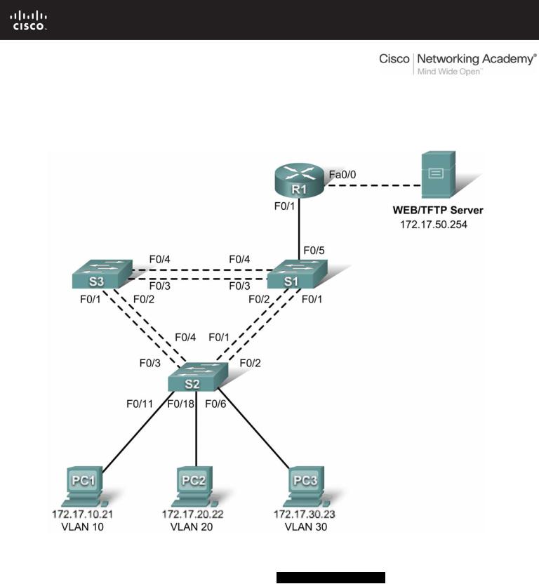
Topology Diagram
Addressing Table
|
Device |
|
|
Interface |
|
|
IP Address |
|
Subnet Mask |
|
Default Gateway |
|
|
(Hostname) |
|
|
|
|
|
|
|
||||
|
|
|
|
|
|
|
|
|
|
|
|
|
|
S1 |
|
VLAN 99 |
172.17.99.11 |
|
255.255.255.0 |
172.17.99.1 |
|
||||
|
|
|
|
|
|
|
|
|
||||
|
S2 |
|
VLAN 99 |
172.17.99.12 |
|
255.255.255.0 |
172.17.99.1 |
|
||||
|
|
|
|
|
|
|
|
|
||||
|
S3 |
|
VLAN 99 |
172.17.99.13 |
|
255.255.255.0 |
172.17.99.1 |
|
||||
|
|
|
|
|
|
|
|
|
|
|
|
|
All contents are Copyright © 1992–2007 Cisco Systems, Inc. All rights reserved. This document is Cisco Public Information. Page 1 of 14

CCNA Exploration |
|
LAN Switching and Wireless: Inter-VLAN Routing |
Lab 6.4.1: Basic Inter-VLAN Routing |
R1 |
Fa 0/0 |
172.17.50.1 |
255.255.255.0 |
N/A |
|
|
|
|
|
R1 |
Fa 0/1 |
See Interface Configuration Table |
N/A |
|
|
|
|
|
|
PC1 |
NIC |
172.17.10.21 |
255.255.255.0 |
172.17.10.1 |
|
|
|
|
|
PC2 |
NIC |
172.17.20.22 |
255.255.255.0 |
172.17.20.1 |
|
|
|
|
|
PC3 |
NIC |
172.17.30.23 |
255.255.255.0 |
172.17.30.1 |
|
|
|
|
|
Server |
NIC |
172.17.50.254 |
255.255.255.0 |
172.17.50.1 |
|
|
|
|
|
Port Assignments – Switch 2
Ports |
|
Assignment |
Network |
Fa0/1 – 0/5 |
802.1q Trunks (Native VLAN 99) |
172.17.99.0 /24 |
|
Fa0/6 – 0/10 |
VLAN 30 |
– Guest (Default) |
172.17.30.0 /24 |
Fa0/11 – 0/17 |
VLAN 10 |
– Faculty/Staff |
172.17.10.0 /24 |
Fa0/18 – 0/24 |
VLAN 20 |
- Students |
172.17.20.0 /24 |
Interface Configuration Table – Router 1
Interface |
|
Assignment |
IP Address |
Fa0/1.1 |
VLAN1 |
|
172.17.1.1 /24 |
Fa0/1.10 |
VLAN 10 |
|
172.17.10.1 /24 |
Fa0/1.20 |
VLAN 20 |
|
172.17.20.1 /24 |
Fa0/1.30 |
VLAN 30 |
|
172.17.30.1 /24 |
Fa0/1.99 |
VLAN 99 |
|
172.17.99.1 /24 |
Learning Objectives
Upon completion of this lab, you will be able to:
•Cable a network according to the topology diagram
•Clear configurations and reload a switch and a router to the default state
•Perform basic configuration tasks on a switched LAN and router
•Configure VLANs and VLAN Trunking Protocol (VTP) on all switches
•Demonstrate and explain the impact of Layer 3 boundaries imposed by creating VLANs
•Configure a router to support 802.1q trunking on a Fast Ethernet interface
•Configure a router with subinterfaces corresponding to the configured VLANs
•Demonstrate and explain inter-VLAN routing
Task 1: Prepare the Network
Step 1: Cable a network that is similar to the one in the topology diagram.
The output shown in this lab is based on 2960 switches and an 1841 router. You can use any current switches or routers in your lab as long as they have the required interfaces shown in the topology diagram. Other device types may produce different output. Note that Ethernet (10Mb) LAN interfaces on routers do not support trunking, and Cisco IOS software earlier than version 12.3 may not support trunking on Fast Ethernet router interfaces.
All contents are Copyright © 1992–2007 Cisco Systems, Inc. All rights reserved. This document is Cisco Public Information. Page 2 of 14

CCNA Exploration |
|
LAN Switching and Wireless: Inter-VLAN Routing |
Lab 6.4.1: Basic Inter-VLAN Routing |
Set up console connections to all three switches and to the router.
Step 2: Clear any existing configurations on the switches.
Clear NVRAM, delete the vlan.dat file, and reload the switches. Refer to lab 2.2.1 if necessary for the procedure. After the reload is complete, use the show vlan command to confirm that only default VLANs exist and that all ports are assigned to VLAN 1.
Switch#show vlan
VLAN |
Name |
Status |
Ports |
---- |
-------------------------------- |
--------- |
----------------------------- |
1 |
default |
active |
Fa0/1, Fa0/2, Fa0/3, Fa0/4 |
|
|
|
Fa0/5, Fa0/6, Fa0/7, Fa0/8 |
|
|
|
Fa0/9, Fa0/10, Fa0/11, Fa0/12 |
|
|
|
Fa0/13, Fa0/14, Fa0/15,Fa0/16 |
|
|
|
Fa0/17, Fa0/18, Fa0/19,Fa0/20 |
|
|
|
Fa0/21, Fa0/22, Fa0/23,Fa0/24 |
1002 |
fddi-default |
active |
Gig0/1, Gig0/2 |
|
|||
1003 |
token-ring-default |
active |
|
1004 |
fddinet-default |
active |
|
1005 |
trnet-default |
active |
|
Step 3: Disable all ports using the shutdown command.
Ensure that the initial switch port states are inactive by disabling all ports. Use the interface range command to simplify this task. Repeat these commands on each switch in the topology.
Switch(config)#interface range fa0/1-24
Switch(config-if-range)#shutdown Switch(config-if-range)#interface range gi0/1-2 Switch(config-if-range)#shutdown
Task 2: Perform Basic Switch Configurations
Step 1: Configure the S1, S2, and S3 switches.
Use the addressing table and the following guidelines:
•Configure the switch hostname.
•Disable DNS lookup.
•Configure an enable secret password of class.
•Configure a password of cisco for console connections.
•Configure a password of cisco for vty connections.
•Configure the default gateway on each switch
Output for S1 shown
Switch>enable
Switch#configure terminal
Enter configuration commands, one per line. End with CNTL/Z. Switch(config)#hostname S1
S1(config)#enable secret class S1(config)#no ip domain-lookup S1(config)#ip default-gateway 172.17.99.1
All contents are Copyright © 1992–2007 Cisco Systems, Inc. All rights reserved. This document is Cisco Public Information. Page 3 of 14

CCNA Exploration |
|
LAN Switching and Wireless: Inter-VLAN Routing |
Lab 6.4.1: Basic Inter-VLAN Routing |
S1(config)#line console 0
S1(config-line)#password cisco S1(config-line)#login S1(config-line)#line vty 0 15 S1(config-line)#password cisco S1(config-line)#login S1(config-line)#end
%SYS-5-CONFIG_I: Configured from console by console S1#copy running-config startup-config
Destination filename [startup-config]? [enter] Building configuration...
Step 2: Re-enable the active user ports on S2 in access mode.
S2(config)#interface fa0/6
S2(config-if)#switchport mode access
S2(config-if)#no shutdown
S2(config-if)#interface fa0/11
S2(config-if)#switchport mode access
S2(config-if)#no shutdown
S2(config-if)#interface fa0/18
S2(config-if)#switchport mode access
S2(config-if)#no shutdown
Task 3: Configure the Ethernet Interfaces on the Host PCs
Configure the Ethernet interfaces of PC1, PC2, PC3 and the remote TFTP/Web Server with the IP addresses from the addressing table.
Task 4: Configure VTP on the Switches
Step 1: Configure VTP on the three switches using the following table. Remember that VTP domain names and passwords are case-sensitive.
Switch Name |
VTP Operating Mode |
VTP Domain |
VTP Password |
|
|
|
|
S1 |
Server |
Lab6 |
cisco |
|
|
|
|
S2 |
Client |
Lab6 |
cisco |
|
|
|
|
S3 |
Client |
Lab6 |
cisco |
|
|
|
|
S1:
S1(config)#vtp mode server
Device mode already VTP SERVER.
S1(config)#vtp domain Lab6
Changing VTP domain name from NULL to Lab6
S1(config)#vtp password cisco
Setting device VLAN database password to cisco
S1(config)#end
S2:
S2(config)#vtp mode client
All contents are Copyright © 1992–2007 Cisco Systems, Inc. All rights reserved. This document is Cisco Public Information. Page 4 of 14

CCNA Exploration |
|
LAN Switching and Wireless: Inter-VLAN Routing |
Lab 6.4.1: Basic Inter-VLAN Routing |
Setting device to VTP CLIENT mode
S2(config)#vtp domain Lab6
Changing VTP domain name from NULL to Lab6
S2(config)#vtp password cisco
Setting device VLAN database password to cisco
S2(config)#end
S3:
S3(config)#vtp mode client
Setting device to VTP CLIENT mode
S3(config)#vtp domain Lab6
Changing VTP domain name from NULL to Lab6
S3(config)#vtp password cisco
Setting device VLAN database password to cisco
S3(config)#end
Step 2: Configure trunking ports and designate the native VLAN for the trunks.
Configure Fa0/1 through Fa0/5 as trunking ports, and designate VLAN 99 as the native VLAN for these trunks. Use the interface range command in global configuration mode to simplify this task.
S1(config)#interface range fa0/1-5
S1(config-if-range)#switchport mode trunk
S1(config-if-range)#switchport trunk native vlan 99
S1(config-if-range)#no shutdown S1(config-if-range)#end
S2(config)# interface range fa0/1-5
S2(config-if-range)#switchport mode trunk
S2(config-if-range)#switchport trunk native vlan 99
S2(config-if-range)#no shutdown
S2(config-if-range)#end
S3(config)# interface range fa0/1-5
S3(config-if-range)#switchport mode trunk
S3(config-if-range)#switchport trunk native vlan 99
S3(config-if-range)#no shutdown
S3(config-if-range)#end
Step 3: Configure VLANs on the VTP server.
Configure the following VLANS on the VTP server:
VLAN |
VLAN Name |
VLAN 99 |
management |
VLAN 10 |
faculty-staff |
VLAN 20 |
students |
VLAN 30 |
guest |
S1(config)#vlan 99
S1(config-vlan)#name management
S1(config-vlan)#exit
S1(config)#vlan 10
All contents are Copyright © 1992–2007 Cisco Systems, Inc. All rights reserved. This document is Cisco Public Information. Page 5 of 14

CCNA Exploration |
|
LAN Switching and Wireless: Inter-VLAN Routing |
Lab 6.4.1: Basic Inter-VLAN Routing |
S1(config-vlan)#name faculty-staff
S1(config-vlan)#exit
S1(config)#vlan 20
S1(config-vlan)#name students
S1(config-vlan)#exit
S1(config)#vlan 30
S1(config-vlan)#name guest
S1(config-vlan)#end
Verify that the VLANs have been created on S1 with the show vlan brief command.
Step 4: Verify that the VLANs created on S1 have been distributed to S2 and S3.
Use the show vlan brief command on S2 and S3 to verify that the four VLANs have been distributed to the client switches.
S2#show vlan brief
VLAN |
Name |
Status |
Ports |
---- |
-------------------------------- |
--------- |
----------------------------- |
1 |
default |
active |
Fa0/1, Fa0/2, Fa0/4, Fa0/5 |
|
|
|
Fa0/6, Fa0/7, Fa0/8, Fa0/9 |
|
|
|
Fa0/10, Fa0/11, Fa0/12,Fa0/13 |
|
|
|
Fa0/14, Fa0/15, Fa0/16,Fa0/17 |
|
|
|
Fa0/18, Fa0/19, Fa0/20,Fa0/21 |
|
|
|
Fa0/22, Fa0/23, Fa0/24, Gi0/1 |
10 |
faculty-staff |
active |
Gi0/2 |
|
|||
20 |
students |
active |
|
30 |
guest |
active |
|
99 |
management |
active |
|
Step 5: Configure the management interface address on all three switches.
S1(config)#interface vlan 99
S1(config-if)#ip address 172.17.99.11 255.255.255.0
S1(config-if)#no shutdown
S1(config-if)#end
S2(config)#interface vlan 99
S2(config-if)#ip address 172.17.99.12 255.255.255.0
S2(config-if)#no shutdown
S2(config-if)#end
S3(config)#interface vlan 99
S3(config-if)#ip address 172.17.99.13 255.255.255.0
S3(config-if)#no shutdown
S3(config-if)#end
Verify that the switches are correctly configured by pinging between them. From S1, ping the management interface on S2 and S3. From S2, ping the management interface on S3.
Were the pings successful? ___________________________________________________________________
If not, troubleshoot the switch configurations and try again.
Step 6: Assign switch ports to VLANs on S2.
Refer to the port assignments table at the beginning of the lab to assign ports to VLANs on S2.
All contents are Copyright © 1992–2007 Cisco Systems, Inc. All rights reserved. This document is Cisco Public Information. Page 6 of 14

CCNA Exploration |
|
LAN Switching and Wireless: Inter-VLAN Routing |
Lab 6.4.1: Basic Inter-VLAN Routing |
S2(config)#interface range fa0/6-10 S2(config-if-range)#switchport access vlan 30 S2(config-if-range)#interface range fa0/11-17 S2(config-if-range)#switchport access vlan 10 S2(config-if-range)#interface range fa0/18-24 S2(config-if-range)#switchport access vlan 20
S2(config-if-range)#end
S2#copy running-config startup-config
Destination filename [startup-config]? [enter] Building configuration...
[OK]
Step 7: Check connectivity between VLANs.
Open command windows on the three hosts connected to S2. Ping from PC1 (172.17.10.21) to PC2 (172.17.20.22). Ping from PC2 to PC3 (172.17.30.23).
Are the pings successful? _____________________________________________________________________
If not, why do these pings fail?__________________________________________________________________
__________________________________________________________________________________________
__________________________________________________________________________________________
Task 5: Configure the Router and the Remote Server LAN
Step 1: Clear the configuration on the router and reload.
Router#erase nvram:
Erasing the nvram filesystem will remove all configuration files! Continue? [confirm]
Erase of nvram: complete Router#reload
System configuration has been modified. Save? [yes/no]: no
Step 2: Create a basic configuration on the router.
•Configure the router with hostname R1.
•Disable DNS lookup.
•Configure an EXEC mode password of cisco.
•Configure a password of cisco for console connections.
•Configure a password of cisco for vty connections.
Step 3: Configure the trunking interface on R1.
You have demonstrated that connectivity between VLANs requires routing at the network layer, exactly like connectivity between any two remote networks. There are a couple of options for configuring routing between VLANs.
The first is something of a brute force approach. An L3 device, either a router or a Layer 3 capable switch, is connected to a LAN switch with multiple connections—a separate connection for each VLAN that requires inter-VLAN connectivity. Each of the switch ports used by the L3 device is configured in a different VLAN on the switch. After IP addresses are assigned to the interfaces on the L3 device, the routing table has directly connected routes for all VLANS, and inter-VLAN routing is enabled. The limitations to this approach are the lack of sufficient Fast Ethernet ports on routers, under-utilization of
All contents are Copyright © 1992–2007 Cisco Systems, Inc. All rights reserved. This document is Cisco Public Information. Page 7 of 14

CCNA Exploration |
|
LAN Switching and Wireless: Inter-VLAN Routing |
Lab 6.4.1: Basic Inter-VLAN Routing |
ports on L3 switches and routers, and excessive wiring and manual configuration. The topology used in this lab does not use this approach.
An alternative approach is to create one or more Fast Ethernet connections between the L3 device (the router) and the distribution layer switch, and to configure these connections as dot1q trunks. This allows all inter-VLAN traffic to be carried to and from the routing device on a single trunk. However, it requires that the L3 interface be configured with multiple IP addresses. This can be done by creating “virtual” interfaces, called subinterfaces, on one of the router Fast Ethernet ports and configuring them to dot1q aware.
Using the subinterface configuration approach requires these steps:
•Enter subinterface configuration mode
•Establish trunking encapsulation
•Associate a VLAN with the subinterface
•Assign an IP address from the VLAN to the subinterface The commands are as follows:
R1(config)#interface fastethernet 0/1
R1(config-if)#no shutdown
R1(config-if)#interface fastethernet 0/1.1
R1(config-subif)#encapsulation dot1q 1
R1(config-subif)#ip address 172.17.1.1 255.255.255.0
R1(config-if)#interface fastethernet 0/1.10
R1(config-subif)#encapsulation dot1q 10
R1(config-subif)#ip address 172.17.10.1 255.255.255.0
R1(config-if)#interface fastethernet 0/1.20
R1(config-subif)#encapsulation dot1q 20
R1(config-subif)#ip address 172.17.20.1 255.255.255.0
R1(config-if)#interface fastethernet 0/1.30
R1(config-subif)#encapsulation dot1q 30
R1(config-subif)#ip address 172.17.30.1 255.255.255.0
R1(config-if)#interface fastethernet 0/1.99
R1(config-subif)#encapsulation dot1q 99 native
R1(config-subif)#ip address 172.17.99.1 255.255.255.0
Note the following points in this configuration:
•The physical interface is enabled using the no shutdown command, because router interfaces are down by default. The virtual interfaces are up by default.
•The subinterface can use any number that can be described with 32 bits, but it is good practice to assign the number of the VLAN as the interface number, as has been done here.
•The native VLAN is specified on the L3 device so that it is consistent with the switches. Otherwise, VLAN 1 would be the native VLAN by default, and there would be no communication between the router and the management VLAN on the switches.
Confirm creation and status of the subinterfaces with the show ip interface brief command:
R1#show ip interface brief |
OK? Method Status |
Protocol |
|
Interface |
IP-Address |
||
All contents are Copyright © 1992–2007 Cisco Systems, Inc. All rights reserved. This document is Cisco Public Information. Page 8 of 14
CCNA Exploration |
|
LAN Switching and Wireless: Inter-VLAN Routing |
Lab 6.4.1: Basic Inter-VLAN Routing |
FastEthernet0/0 unassigned FastEthernet0/1 unassigned FastEthernet0/1.1 172.17.1.1 FastEthernet0/1.10 172.17.10.1 FastEthernet0/1.20 172.17.20.1 FastEthernet0/1.30 172.17.30.1 FastEthernet0/1.99 172.17.99.1
YES unset |
administratively down down |
|
YES unset |
up |
up |
YES manual |
up |
up |
YES manual |
up |
up |
YES manual |
up |
up |
YES manual |
up |
up |
YES manual |
up |
up |
Step 4: Configure the server LAN interface on R1.
R1(config)# interface FastEthernet0/0
R1(config-if)#ip address 172.17.50.1 255.255.255.0
R1(config-if)#description server interface
R1(config-if)#no shutdown
R1(config-if)#end
There are now six networks configured. Verify that you can route packets to all six by checking the routing table on R1.
R1#show ip route
<output omitted>
Gateway of last resort is not set
172.17.0.0/24 is subnetted, 6 subnets
C 172.17.50.0 is directly connected, FastEthernet0/0
C 172.17.30.0 is directly connected, FastEthernet0/1.30 C 172.17.20.0 is directly connected, FastEthernet0/1.20 C 172.17.10.0 is directly connected, FastEthernet0/1.10 C 172.17.1.0 is directly connected, FastEthernet0/1.1 C 172.17.99.0 is directly connected, FastEthernet0/1.99
If your routing table does not show all six networks, troubleshoot your configuration and resolve the problem before proceeding.
Step 5: Verify Inter-VLAN routing.
From PC1, verify that you can ping the remote server (172.17.50.254) and the other two hosts (172.17.20.22 and 172.17.30.23). It may take a couple of pings before the end-to-end path is established.
Are the pings successful? _____________________________________________________________________
If not, troubleshoot your configuration. Check to make sure that the default gateways have been set on all PCs and all switches. If any of the hosts have gone into hibernation, the connected interface may go down.
Task 6: Reflection
In Task 5, it was recommended that you configure VLAN 99 as the native VLAN in the router Fa0/0.99 interface configuration. Why would packets from the router or hosts fail when trying to reach the switch management interfaces if the native VLAN were left in default?
__________________________________________________________________________________________
__________________________________________________________________________________________
__________________________________________________________________________________________
__________________________________________________________________________________________
All contents are Copyright © 1992–2007 Cisco Systems, Inc. All rights reserved. This document is Cisco Public Information. Page 9 of 14

CCNA Exploration |
|
LAN Switching and Wireless: Inter-VLAN Routing |
Lab 6.4.1: Basic Inter-VLAN Routing |
Task 7: Clean Up
Erase the configurations and reload the switches. Disconnect and store the cabling. For PC hosts that are normally connected to other networks (such as the school LAN or to the Internet), reconnect the appropriate cabling and restore the TCP/IP settings.
Final Configurations
Router 1
hostname R1
!
enable secret class
!
no ip domain lookup
!
interface FastEthernet0/0
ip address 172.17.50.1 255.255.255.0 no shutdown
!
interface FastEthernet0/1 no shutdown
!
interface FastEthernet0/1.1 encapsulation dot1Q 1
ip address 172.17.1.1 255.255.255.0
!
interface FastEthernet0/1.10 encapsulation dot1Q 10
ip address 172.17.10.1 255.255.255.0
!
interface FastEthernet0/1.20 encapsulation dot1Q 20
ip address 172.17.20.1 255.255.255.0
!
interface FastEthernet0/1.30 encapsulation dot1Q 30
ip address 172.17.30.1 255.255.255.0
!
interface FastEthernet0/1.99 encapsulation dot1Q 99 native
ip address 172.17.99.1 255.255.255.0
!
<output omitted - serial interfaces not configured>
!
line con 0 line aux 0 line vty 0 4 login password cisco
!
Switch 1
!
hostname S1
!
All contents are Copyright © 1992–2007 Cisco Systems, Inc. All rights reserved. This document is Cisco Public Information. Page 10 of 14

CCNA Exploration |
|
LAN Switching and Wireless: Inter-VLAN Routing |
Lab 6.4.1: Basic Inter-VLAN Routing |
enable secret class
!
no ip domain lookup
!
interface FastEthernet0/1 switchport trunk native vlan 99 switchport mode trunk
!
interface FastEthernet0/2 switchport trunk native vlan 99 switchport mode trunk
!
interface FastEthernet0/3 switchport trunk native vlan 99 switchport mode trunk
!
interface FastEthernet0/4 switchport trunk native vlan 99 switchport mode trunk
!
interface FastEthernet0/5 switchport trunk native vlan 99 switchport mode trunk
!
<output omitted - all remaining ports in shutdown>
!
interface Vlan1 no ip address
no ip route-cache
!
interface Vlan99
ip address 172.17.99.11 255.255.255.0 no shutdown
!
ip default-gateway 172.17.99.1 ip http server
!
line con 0
logging synchronous line vty 0 4
login password cisco line vty 5 15 login password cisco
Switch 2
!
hostname S2
!
enable secret class
!
no ip domain lookup
!
interface FastEthernet0/1 switchport trunk native vlan 99
All contents are Copyright © 1992–2007 Cisco Systems, Inc. All rights reserved. This document is Cisco Public Information. Page 11 of 14

CCNA Exploration |
|
LAN Switching and Wireless: Inter-VLAN Routing |
Lab 6.4.1: Basic Inter-VLAN Routing |
switchport mode trunk
!
interface FastEthernet0/2 switchport trunk native vlan 99 switchport mode trunk
!
interface FastEthernet0/3 switchport trunk native vlan 99 switchport mode trunk
!
interface FastEthernet0/4 switchport trunk native vlan 99 switchport mode trunk
!
interface FastEthernet0/5 switchport trunk native vlan 99 switchport mode trunk
!
interface FastEthernet0/6 switchport access vlan 30 switchport mode access
!
interface FastEthernet0/7 switchport access vlan 30
!
interface FastEthernet0/8 switchport access vlan 30
!
interface FastEthernet0/9 switchport access vlan 30
!
interface FastEthernet0/10 switchport access vlan 30
!
interface FastEthernet0/11 switchport access vlan 10 switchport mode access
!
interface FastEthernet0/12 switchport access vlan 10
!
interface FastEthernet0/13 switchport access vlan 10
!
interface FastEthernet0/14 switchport access vlan 10
!
interface FastEthernet0/15 switchport access vlan 10
!
interface FastEthernet0/16 switchport access vlan 10
!
interface FastEthernet0/17 switchport access vlan 10
!
All contents are Copyright © 1992–2007 Cisco Systems, Inc. All rights reserved. This document is Cisco Public Information. Page 12 of 14

CCNA Exploration |
|
LAN Switching and Wireless: Inter-VLAN Routing |
Lab 6.4.1: Basic Inter-VLAN Routing |
interface FastEthernet0/18 switchport access vlan 20
!
interface FastEthernet0/19 switchport access vlan 20
!
interface FastEthernet0/20 switchport access vlan 20
!
interface FastEthernet0/21 switchport access vlan 20
!
interface FastEthernet0/22 switchport access vlan 20
!
interface FastEthernet0/23 switchport access vlan 20
!
interface FastEthernet0/24 switchport access vlan 20
!
interface Vlan1 no ip address
no ip route-cache
!
interface Vlan99
ip address 172.17.99.12 255.255.255.0 no shutdown
!
ip default-gateway 172.17.99.1 ip http server
!
line con 0 password cisco
logging synchronous login
line vty 0 4 password cisco login
line vty 5 15 password cisco login
!
end
Switch 3
!
hostname S3
!
enable secret class
!
no ip domain lookup
!
interface FastEthernet0/1 switchport trunk native vlan 99
All contents are Copyright © 1992–2007 Cisco Systems, Inc. All rights reserved. This document is Cisco Public Information. Page 13 of 14

CCNA Exploration |
|
LAN Switching and Wireless: Inter-VLAN Routing |
Lab 6.4.1: Basic Inter-VLAN Routing |
switchport mode trunk
!
interface FastEthernet0/2 switchport trunk native vlan 99 switchport mode trunk
!
interface FastEthernet0/3 switchport trunk native vlan 99 switchport mode trunk
!
interface FastEthernet0/4 switchport trunk native vlan 99 switchport mode trunk
!
interface FastEthernet0/5 switchport trunk native vlan 99 switchport mode trunk
!
<output omitted - all remaining ports in shutdown>
!
interface Vlan99
ip address 172.17.99.13 255.255.255.0 no shutdown
!
ip default-gateway 172.17.99.1 ip http server
!
control-plane
!
line con 0 password cisco login
line vty 0 4 password cisco login
line vty 5 15 password cisco login
!
end
All contents are Copyright © 1992–2007 Cisco Systems, Inc. All rights reserved. This document is Cisco Public Information. Page 14 of 14