

Related Protocols |
265 |
Encapsulation is another approach that is only useful for SIP/PSTN gateways. Using this approach, PSTN-to-SIP translation is done to construct the appropriate SIP message, then the PSTN protocol message is encapsulated and included with the SIP message as a message body. If the SIP message is received by another SIP/PSTN gateway, the resulting PSTN signaling message is constructed from both the SIP message and the encapsulated PSTN message that was received by the other gateway. This approach offers the possibility of transparency (i.e., no loss of PSTN information as a call is carried across a SIP network). However, this only works in a network in which only one variation of PSTN protocol is used. Unlike Internet protocols, PSTN protocols vary by region and are not compatible without a special type of PSTN switch capable of converting one message format to another. There are many dozens of protocol variants used throughout the world.
Another disadvantage of encapsulation is that the PSTN message bodies must be encrypted if they are transported over the public Internet, or used in a network with native SIP devices. This is because private information can be carried in PSTN messages because PSTN protocols assume a different trust model than an Internet protocol such as SIP. To prevent accidental disclosure of this information, the message bodies must be encrypted by the originating gateway and decrypted by the terminating gateway, which adds significant processing requirements and call setup delay.
Encapsulated PSTN messages are carried as MIME bodies, which have been standardized for both ISUP and QSIG [6].
11.3 Media Gateway Control Protocols
There are a number of protocols used to decompose the operation of a gateway, which are often used in SIP/PSTN gateways. These protocols are known generally as media gateway control protocols. Their relation to a signaling protocol such as SIP is shown in Figure 11.1. Media gateway control protocols are not peer-level signaling protocols—they do not perform the rendezvous and negotiation functions of a signaling protocol such as SIP. Instead, they allow a gateway to be decomposed into a signaling element and a media component. The media component, a media gateway (MG), can provide PSTN trunks or RTP/ SRTP connections, which are under the control of the media gateway controller (MGC). The MGC in turn uses a signaling protocol such as SIP or PSTN signaling to setup connections with other elements. Media gateway controllers used to be called softswitches. Often, a single or pair of media gateway controllers will control a number of media gateways. Media gateway control protocols are master/slave protocols—the MGC tells the MG what to do—there is no negotiation between them. Some common media gateway control protocols include

266 |
SIP: Understanding the Session Initiation Protocol |
Figure 11.1 SIP and media gateway control protocols.
MGCP [7] and H.248 [8]. H.248 was initially jointly published by the ITU-T as H.248 and in the IETF as MEGACO [9]. The current version is maintained by the ITU-T as H.248.1 version 1 [10].
11.4 H.323
A related Internet communications protocol is the ITU recommendation H.323, entitled “Packet-Based Multimedia Communication.” H.323 is introduced as a related protocol to SIP for signaling VoIP and multimedia communication.
11.4.1 Introduction to H.323
H.323 [11] is an umbrella recommendation that covers all aspects of multimedia communication over packet networks. It is part of the H.32x series of protocols that describes multimedia communication over ISDN, broadband (ATM), telephone (PSTN), and packet (IP) networks, as shown in Table 11.1. Originally developed for video conferencing over a single LAN segment, the protocol has been extended to cover the general problem of telephony over the Internet. The first version was approved by the ITU in 1996 and was adopted by early IP telephony networks. Version 2 was adopted in 1998 to fix some of the problems and limitations in version 1. Version 3 was adopted in 1999 and includes modifications and extensions to enable communications over a larger network. Version 4 was adopted in 2000 with some major changes to the protocol. Versions 5 and 6 made very small changes to the protocol.
Related Protocols |
267 |
Table 11.1
TU H.32x Family of Standards
Protocol Title
H.320 Communication over ISDN networks
H.321 Communication over broadband ISDN (ATM) networks
H.322 Communication over LANs with guaranteed QoS
H.323 Communication over LANs with nonguaranteed QoS (IP)
H.324 Communication over PSTN (V.34 modems)
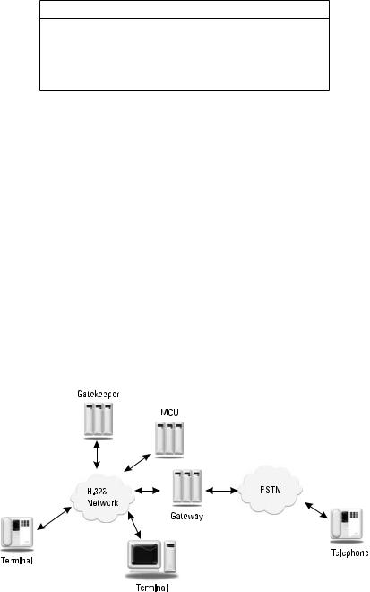
H.323 references a number of other ITU and IETF protocols to completely specify the environment. Each element of the network is defined and standardized. Figure 11.2 shows the main elements: terminals, gatekeepers, gateways, and multipoint control units (MCUs). Terminals, gateways, and MCUs are network end-devices, often called end points. An end point originates and terminates media streams that could be audio, video, or data, or a combination of all three. At a minimum, all H.323 end points must support basic G.711 PCM audio transmission. Support of video and data are optional. An H.323 gatekeeper is a server that controls a zone, which is the smallest administrative domain in H.323. If a gatekeeper is present, all end points within that zone must register with and defer to the gatekeeper on authorization decisions to place or accept a call. A gatekeeper also provides services to terminals in a zone, such as gateway location, address translation, bandwidth management, feature implementation, and registration. A gatekeeper is not a required element in an H.323 network, but a terminal’s capabilities without one are severely limited. A gateway is another optional element in an H.323 network. It interfaces the H.323
Figure 11.2 Elements of an H.323 network.
268 |
SIP: Understanding the Session Initiation Protocol |
network with another protocol network, such as the PSTN. An MCU provides conferencing services for terminals.
Some of the protocols referenced by H.323 are shown in Table 11.2. H.225 is used for registration, admission, and status (RAS), which is used for terminal- to-gatekeeper communication. A modified subset of Q.931 is used for call setup signaling between terminals. (The H.323 usage of Q.931 is not compatible with Q.931 as used in an ISDN network.) H.245 is used for control signaling or media negotiation and capability exchange between terminals. T.120 is used for multipoint graphic communications. H.323 audio codecs are specified in the ITU G.7xx series. Video codecs are specified in the H.26x series. H.323 also references two IETF protocols, RTP and RTCP, for the media transport which are described in Chapter 12. The H.235 recommendation covers privacy and encryption, while H.450 covers supplementary services such as those commonly found in the PSTN (e.g., call forwarding, call hold, and call park).
11.4.2 Example of H.323
Figure 11.3 shows a basic call flow involving two terminals and a gatekeeper. The flow shows the interaction between the various elements and the various protocols used to establish the session. The call begins with an exchange of H.225.0 RAS messages between the calling terminal and the gatekeeper. All RAS messages are transported using UDP. It is assumed that both terminals have already registered with the gatekeeper using the registration request (RRQ) message. The calling terminal sends an admission request (ARQ) message to the gatekeeper containing the address of the called terminal and the type of session desired. The address could be specified as an H.323 alias, E.164 telephone number, e-mail address, or URL [12]. The gatekeeper knows about all calls in the zone it controls; it decides if the user is authorized to make a call and if there is enough bandwidth or other resources available. In this example, there is enough bandwidth, so the gatekeeper allows the call to continue by sending an admission confirmation
|
Table 11.2 |
|
Protocols Referenced by H.323 |
Protocol |
Description |
|
|
H.225 |
Registration, admission, and status (RAS) and call signaling |
H.245 |
Control signaling (media control) |
T.120 |
Multipoint graphic communication |
G.7xx |
Audio codecs |
H.26x |
Video codecs |
RTP |
Real-time transport protocol (RFC 3550) |
RTCP |
RTP control protocol (RFC 3550) |
H.235 |
Privacy and encryption |
H.450 |
Supplementary services |
|
|
|
|
|
Related Protocols |
269 |
|||||||||||||||||
|
|
|
|
|
|
|
|
|
|
|
|
|
|
|
|
|
|
|
|
|
|
|
|
|
|
|
|
|
|
|
|
|
|
|
|
|
|
|
|
|
|
|
|
|
|
|
|
|
|
|
|
|
|
|
|
|
|
|
|
|
|
|
|
|
|
|
|
|
|
|
|
|
|
|
|
|
|
|
|
|
|
|
|
|
|
|
|
|
|
|
|
|
|
|
|
|
|
|
|
|
|
|
|
|
|
|
|
|
|
|
|
|
|
|
|
|
|
|
|
|
|
|
|
|
|
|
|
|
|
|
|
|
|
|
|
|
|
|
|
|
|
|
|
|
|
|
|
|
|
|
|
|
|
|
|
|
|
|
|
|
|
|
|
|
|
|
|
|
|
|
|
|
|
|
|
|
|
|
|
|
|
|
|
|
|
|
|
|
|
|
|
|
|
|
|
|
|
|
|
|
|
|
|
|
|
|
|
|
|
|
|
|
|
|
|
|
|
|
|
|
|
|
|
|
|
|
|
|
|
|
|
|
|
|
|
|
|
|
|
|
|
|
|
|
|
|
|
|
|
|
|
|
|
|
|
|
|
|
|
|
|
|
|
|
|
|
|
|
|
|
|
|
|
|
|
|
|
|
|
|
|
|
|
|
|
|
|
|
|
|
|
|
|
|
|
|
|
|
|
|
|
|
|
|
|
|
|
|
|
|
|
|
|
|
|
|
|
|
|
|
|
|
|
|
|
|
|
|
|
|
|
|
|
|
|
|
|
|
|
|
|
|
|
|
|
|
|
|
|
|
|
|
|
|
|
|
|
|
|
|
|
|
|
|
|
|
|
|
|
|
|
|
|
|
|
|
|
|
|
|
|
|
|
|
|
|
|
|
|
|
|
|
|
|
|
|
|
|
|
|
|
|
|
|
|
|
|
|
|
|
|
|
|
|
|
|
|
|
|
|
|
|
|
|
|
|
|
|
|
|
|
|
|
|
|
|
|
|
|
|
|
|
|
|
|
|
|
|
|
|
|
|
|
|
|
|
|
|
|
|
|
|
|
|
|
|
|
|
|
|
|
|
|
|
|
|
|
|
|
|
|
|
|
|
|
|
|
|
|
|
|
|
|
|
|
|
|
|
|
|
|
|
|
|
|
|
|
|
|
|
|
|
|
|
|
|
|
|
|
|
|
|
|
|
|
|
|
|
|
|
|
|
|
|
|
|
|
|
|
|
|
|
|
|
|
|
|
|
|
|
|
|
|
|
|
|
|
|
|
|
|
|
|
|
|
|
|
|
|
|
|
|
|
|
|
|
|
|
|
|
|
|
|
|
|
|
|
|
|
|
|
|
|
|
|
|
|
|
|
|
|
|
|
|
|
|
|
|
|
|
|
|
|
|
|
|
|
|
|
|
|
|
|
|
|
|
|
|
|
|
|
|
|
|
|
|
|
|
|
|
|
|
|
|
|
|
|
|
|
|
|
|
|
|
|
|
|
|
|
|
|
|
|
|
|
|
|
|
|
|
|
|
|
|
|
|
|
|
|
|
|
|
|
|
|
|
|
|
|
|
|
|
|
|
|
|
|
|
|
|
|
|
|
|
|
|
|
|
|
|
|
|
|
|
|
|
|
|
|
|
|
|
|
|
|
|
|
|
|
|
|
|
|
|
|
|
|
|
|
|
|
|
|
|
|
|
|
|
|
|
|
|
|
|
|
|
|
|
|
|
|
|
|
|
|
|
|
|
|
|
|
|
|
|
|
|
|
|
|
|
|
|
|
|
|
|
|
|
|
|
|
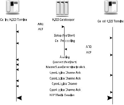
Figure 11.3 H.323 call flow example.
(ACF) message. The ACF indicates to the calling terminal that end-point message routing, or the direct exchange of H.225 call signaling messages with the called terminal, is to be used. Alternatively, the gatekeeper can require gatekeeper routed signaling, where the gatekeeper acts like a proxy and forwards all signaling messages between the terminals. The gatekeeper has also translated the destination in the ARQ into a transport address that was returned in the ACF.
The calling terminal is now able to open a TCP connection to the called terminal using the transport address returned in the ACF and send a Q.931 Setup message to the called terminal. The called terminal responds with a Call Proceeding response to the calling terminal. The called terminal must also get permission from the gatekeeper before it accepts the call, so an ARQ is sent to the gatekeeper. When it receives the ACF from the gatekeeper, the called terminal begins alerting the user and sends an Alerting message to the calling terminal. When the user at the calling terminal answers, a Connect message is sent. There is no acknowledgment of messages because all these messages are sent using TCP, which provides reliable transport. These call signaling messages used in H.323 are a subset of the Q.931 protocol that covers ISDN D-channel signaling.
Figure 11.3 shows the use of H.323 FastStart, in which the Setup message contains the TerminalCapabilitySet information. This saves multiple messages and round trips compared to opening a second TCP connection between the
270 |
SIP: Understanding the Session Initiation Protocol |
terminals. In H.245 tunneling, a separate H.245 control channel is not opened. Instead, H.245 messages are encapsulated in Q.931 messages in the call signaling channel. This saves overhead in opening and closing a second TCP connection. Now, the terminals begin sending RTP media packets and also RTCP control packets using the IP addresses and port numbers exchanged in the OpenLogicalChannel messages.
Figure 11.4 shows a call tear down sequence, which either terminal may initiate. In this example, the called terminal sends an EndSessionCommand message in the H.245 control signaling channel. The other terminal responds with an EndSessionCommand message in the H.245 control signaling channel, which can now be closed. The called terminal then sends a disengage request (DRQ) message and receives a disengage confirmation (DCF) message from the gatekeeper. This way, the gatekeeper knows that the resources used in the call have now been freed up. A call detail record (CDR) or other billing record can be written and stored by the gatekeeper. Next, a Q.931 release complete message is sent in the call signaling connection, which can then be closed. Finally, the other terminal sends a DRQ to the gatekeeper over UDP and receives a DCF response.
The call flows in Figures 11.3 and 11.4 show direct end-point signaling, in which the calling terminal opens TCP connections to the called terminal and exchanges H.225.0 and H.245 messages. In the ACF response to the calling terminal, the gatekeeper can require gatekeeper routed signaling, where the call signaling and control signaling channels are opened with the gatekeeper, who then opens the channels with the called terminal. In this way, the gatekeeper stays in
Figure 11.4 H.323 call teardown sequence.