
- •1 STM8 architecture
- •1.1 STM8 development support
- •1.2 Enhanced STM8 features
- •2 Glossary
- •3 STM8 core description
- •3.1 Introduction
- •3.2 CPU registers
- •4 STM8 memory interface
- •4.1 Program space
- •4.2 Data space
- •Figure 3. Address spaces
- •4.3 Memory interface architecture
- •Figure 4. Memory Interface Architecture
- •5 Pipelined execution
- •Figure 5. Pipelined execution principle
- •5.1 Description of pipelined execution stages
- •Figure 6. Pipelined execution stages
- •5.1.1 Fetch stage
- •5.1.2 Decoding and addressing stage
- •5.1.3 Execution stage
- •5.2 Data memory conflicts
- •5.3 Pipelined execution examples
- •5.4 Conventions
- •5.4.1 Optimized pipeline example – execution from Flash Program memory
- •5.4.2 Optimize pipeline example – execution from RAM
- •5.4.3 Pipeline with Call/Jump
- •Table 11. Legend
- •5.4.4 Pipeline stalled
- •Table 13. Legend
- •5.4.5 Pipeline with 1 wait state
- •Table 15. Legend
- •6 STM8 addressing modes
- •Table 16. STM8 core addressing modes
- •6.1 Inherent addressing mode
- •6.2 Immediate addressing mode
- •Table 19. Immediate addressing instructions
- •Figure 7. Immediate addressing mode example
- •6.3 Direct addressing mode (Short, Long, Extended)
- •Table 21. Available Long and Short Direct addressing mode instructions
- •Table 22. Available Extended Direct addressing mode instructions
- •Table 23. Available Long Direct addressing mode instructions
- •6.3.1 Short Direct addressing mode
- •Figure 8. Short Direct addressing mode example
- •6.3.2 Long Direct addressing mode
- •6.3.3 Extended Direct addressing mode (only for CALLF and JPF)
- •Figure 10. Far Direct addressing mode example
- •6.4 Indexed addressing mode (No Offset, Short, SP, Long, Extended)
- •Table 25. No Offset, Long, Short and SP Indexed instructions
- •6.4.1 No Offset Indexed addressing mode
- •Figure 11. No Offset Indexed addressing mode example
- •6.4.2 Short Indexed addressing mode
- •Figure 12. Short Indexed - 8-bit offset - addressing mode example
- •6.4.3 SP Indexed addressing mode
- •Figure 13. SP Indexed - 8-bit offset - addressing mode example
- •6.4.4 Long Indexed addressing mode
- •Figure 14. Long Indexed - 16-bit offset - addressing mode example
- •6.4.5 Extended Indexed (only LDF instruction)
- •Figure 15. Far Indexed - 16-bit offset - addressing mode example
- •6.5 Indirect (Short Pointer Long, Long Pointer Long)
- •Table 28. Overview of Indirect addressing instructions
- •Table 29. Available Long Pointer Long and Short Pointer Long Indirect Instructions
- •Table 30. Available Long Pointer Long Indirect Instructions
- •6.6 Short Pointer Indirect Long addressing mode
- •Figure 16. Short Pointer Indirect Long addressing mode example
- •6.7 Long Pointer Indirect Long addressing mode
- •Figure 17. Long Pointer Indirect Long addressing mode example
- •6.8 Indirect Indexed (Short Pointer Long, Long Pointer Long, Long Pointer Extended) addressing mode
- •6.9 Short Pointer Indirect Long Indexed addressing mode
- •Figure 18. Short Pointer Indirect Long Indexed addressing mode example
- •6.10 Long Pointer Indirect Long Indexed addressing mode
- •Figure 19. Long Pointer Indirect Long Indexed addressing mode example
- •6.11 Long Pointer Indirect Extended Indexed addressing mode
- •Figure 20. Long Pointer Indirect Extended Indexed addressing mode example
- •6.12 Relative Direct addressing mode
- •Table 36. Available Relative Direct instructions
- •Figure 21. Relative Direct addressing mode example
- •6.13 Bit Direct (Long) addressing mode
- •Table 38. Available Bit Direct instructions
- •Figure 22. Bit Long Direct addressing mode example
- •6.14 Bit Direct (Long) Relative addressing mode
- •Table 40. Available Bit Direct Relative instructions
- •Figure 23. Bit Long Direct Relative addressing mode example
- •7 STM8 instruction set
- •7.1 Introduction
- •Table 41. Instruction groups
- •7.2 Nomenclature
- •7.2.1 Operators
- •7.2.2 CPU registers
- •7.2.3 Code condition bit value notation
- •7.2.4 Memory and addressing
- •7.2.5 Operation code notation
- •7.3 Instruction set summary
- •7.4 Instruction set
- •ADDW
- •BCCM
- •BCPL
- •BREAK
- •BRES
- •BSET
- •BTJF
- •BTJT
- •CALL
- •CALLF
- •CALLR
- •CLRW
- •CPLW
- •DECW
- •DIVW
- •EXGW
- •HALT
- •INCW
- •IRET
- •JRxx
- •NEGW
- •POPW
- •PUSH
- •PUSHW
- •RETF
- •RLCW
- •RLWA
- •RRCW
- •RRWA
- •SLLW/SLAW
- •SRAW
- •SRLW
- •SUBW
- •SWAP
- •SWAPW
- •TNZW
- •TRAP
- •8 Revision history
- •Table 43. Document revision history

Pipelined execution |
PM0044 |
|
|
5 Pipelined execution
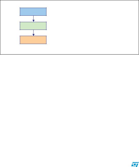
The STM8 family uses a 3-stage pipeline to increase the speed of the flow of instructions sent to the processor. Pipelined execution allows several operations to be performed simultaneously, rather than serially:
●Fetch
●Decode and address
●Execute
The Program Counter (PC) points always to the instruction in decode stage as shown in
Figure 5.
Figure 5. Pipelined execution principle
&%4#(
0# #N
0# $%#/$%
0# N |
%8%#54% |
|
)NSTRUCTIONS S FETCHED FROMDMEMORY
)NSTRUCTIONSIDECODING AND DATADREAD FROMAMEMORYY IF NEEDED
2EGISTER S TDATA READ FROM REGISTERRBANK 3HIFTIANDT!,5AOPERATION 7RITETBACKKREGISTER S SDATA TO 2EGISTER BANK
7RITETBACKKDATA TOTMEMORY
-3 6
5.1Description of pipelined execution stages
Figure 6 and Section 5.1.1, Section 5.1.2, and Section 5.1.3 provide a detailed description of each stage of the pipeline execution.
20/162 |
Doc ID 13590 Rev 3 |