

Hardware and layout |
UM0817 |
|
|
2.4Single touch sensing
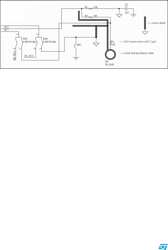
A touch sensing button TS1 is available on the STM8S-DISCOVERY (see Figure 10).
Figure 10. Touch sensing schematic
To disable the touch sensing interface and to use PC1, PC2 and PC3 as standard I/O, you need to unsolder the 2-1 connection and solder 2-3 connection on SB4 and SB3, you also need to unsolder the R2 resistor.
RC acquisition principle
The RC acquisition method detects a human touch on key touch sensor (TS1) by measuring the small variation of the touch electrode capacitance. Electrode capacitance is periodically charged and discharged through a fixed resistor (R6).
The capacitance value depends on the following parameters: electrode area (A), relative dielectric constant of the insulator (eR), the relative permittivity of air (e0) and the distance between the two electrodes.
For more information about touch sensing please refer to AN2927.
10/18 |
Doc ID 16361 Rev 3 |