

Hardware and layout |
UM0817 |
|
|
2.2ST-LINK
The ST-LINK provides a USB interface for programming and debugging using a single wire interface module (SWIM). The ST-LINK module of the STM8S-DISCOVERY also supplies 5 V and 3.3 V to the STM8S105C6T6 module.
2.2.1Using the ST-LINK
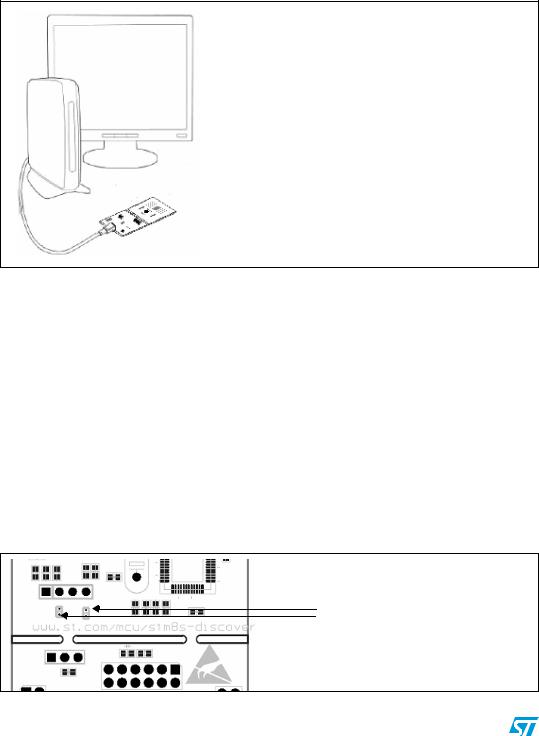
Figure 6. Typical configuration
Hardware requirements: - USB cable type A to B
- Computer with Windows 2000, XP or Vista OS
Software requirement:
ST Toolset (ST Visual Develop and ST Visual Program) which support ST-LINK SWIM
Note: |
The driver for ST-LINK is installed automatically when the USB is connected. |
|
For information about debugging and programming features refer to ST-LINK UM0627, |
|
UM0036 STVD and RN0011 STVP. For information about SWIM refer to UM0470. |
2.2.2 |
Using the ST-LINK on other STM8S applications |
|
You can connect your ST-LINK to other STM8S applications in 2 ways. |
|
● By removing the solder bridges: This way uses the ST-LINK without breaking the PCB. |
|
Unsolder the two solder bridges SB1 and SB2 under the SWIM connector. |
|
See Figure 7. You can re-solder the two bridges at a later date thus keeping the |
|
STM8S-DISCOVERY usable. |
|
● By removing it from your board: This way constitutes a good alternative to programming |
|
the STM8S devices in other applications. See Figure 8. |
Note: |
This ST-LINK only supports the STM8S family. Do not use it with other STM8 families. |
|
Figure 7. ST-LINK without breaking the PCB |
Remove SB1 and SB2 solder bridges
8/18 |
Doc ID 16361 Rev 3 |