

BMW 3 & 5 Series Haynes Manual
.pdf9•2 Braking system |
|
Torque wrench settings |
Nm |
Front disc brake caliper |
|
Caliper guide (mounting) bolts . . . . . . . . . . . . . . . . . . . . . . . . . . . . . . |
30 to 35 |
Caliper bracket-to-strut housing bolts |
|
3-Series, E30 . . . . . . . . . . . . . . . . . . . . . . . . . . . . . . . . . . . . . . . . . . |
123 |
5-Series, E28 (“old-shape”) . . . . . . . . . . . . . . . . . . . . . . . . . . . . . . . |
123 |
5-Series, E34 (“new-shape”) . . . . . . . . . . . . . . . . . . . . . . . . . . . . . . |
110 |
Rear disc brake caliper |
|
Caliper guide (mounting) bolts . . . . . . . . . . . . . . . . . . . . . . . . . . . . . . |
30 to 35 |
Carrier-to-trailing arm bolts . . . . . . . . . . . . . . . . . . . . . . . . . . . . . . . . |
67 |
Brake hose-to-caliper fitting . . . . . . . . . . . . . . . . . . . . . . . . . . . . . . . . . . |
14 to 17 |
Master cylinder-to-brake servo nuts |
|
3-Series . . . . . . . . . . . . . . . . . . . . . . . . . . . . . . . . . . . . . . . . . . . . . . . . |
24 |
5-Series . . . . . . . . . . . . . . . . . . . . . . . . . . . . . . . . . . . . . . . . . . . . . . . . |
25 to 29 |
Brake servo mounting nuts . . . . . . . . . . . . . . . . . . . . . . . . . . . . . . . . . . . |
22 to 24 |
Hydraulic line-to-hydraulic brake servo threaded |
|
fittings - 5-Series, E28 (“old-shape”) . . . . . . . . . . . . . . . . . . . . . . . . . . . |
31 |
Wheel bolts . . . . . . . . . . . . . . . . . . . . . . . . . . . . . . . . . . . . . . . . . . . . . . . |
See Chapter 1 |
1 General information
All 3-Series models, and 5-Series E28 (“oldshape”) models, are equipped with front disc brakes and either rear drum or rear disc brakes. 5-Series E34 (“new-shape”) models have disc brakes front and rear. Front and rear brakes are self-adjusting on all models. Some later models are equipped with an Antilock Braking System (ABS); this is described in Section 2.
Hydraulic system
The hydraulic system consists of two separate circuits. The master cylinder has separate reservoirs for the two circuits; in the event of a leak or failure in one hydraulic circuit, the other circuit will remain operative.
Brake servo
The vacuum brake servo, utilising engine manifold vacuum and atmospheric pressure to provide assistance to the hydraulically operated brakes, is mounted on the bulkhead in the engine compartment.
A hydraulic brake servo system is used on 5-Series E28 models. This system uses hydraulic pressure from the power steering pump to assist braking.
Handbrake
The handbrake operates the rear brakes, and is cable-operated via a lever mounted in the centre console. The handbrake assembly on rear drum brake models is part of the rear drum brake assembly, and is self-adjusting. On rear disc brake models, the handbrake uses a pair of brake shoes located inside the centre portion of the rear brake disc, and is manually-adjusted.
Brake pad wear warning system
The brake pad wear warning system is linked to a red warning light in the instrument
cluster, which comes on when the brake pads have worn down to the point at which they require renewal. DO NOT ignore this reminder. If you don’t renew the pads shortly after the brake pad wear warning light comes on, the brake discs will be damaged.
On some models, the brake pad wear warning system also includes an early warning light that comes on only when the brake pedal is depressed, letting you know in advance that the pads need to be renewed.
The wear sensor is attached to the brake pads. The sensor is located at the left front wheel; on some models, there is another sensor at the right rear wheel. The wear sensor is part of a closed circuit. Once the pads wear down to the point at which they’re flush with the sensor, the disc grinds away the side of the sensor facing the disc. Thus, the wire inside the sensor is broken, and the red light on the instrument panel comes on.
Always check the sensor(s) when renewing the pads. If you change the pads before the warning light comes on, the sensor(s) may still be good; once the light has come on, renew the sensor.
Service
After completing any operation involving dismantling of any part of the brake system, always test drive the vehicle to check for proper braking performance before resuming normal driving. When testing the brakes, try to select a clean, dry, road with no camber (ie as flat as possible) and with no other traffic. Conditions other than these can lead to inaccurate test results.
Test the brakes at various speeds with both light and heavy pedal pressure. The vehicle should stop evenly, without pulling to one side or the other. Avoid locking the brakes, because this slides the tyres and diminishes braking efficiency and control of the vehicle.
Tyres, vehicle load and wheel alignment are factors which also affect braking performance.
2Anti-lock Braking system (ABS) - general information
The Anti-lock Braking System is designed to maintain vehicle control, directional stability and optimum deceleration under severe braking conditions on most road surfaces. It does so by monitoring the rotational speed of each wheel and controlling the brake line pressure to each wheel during braking. This prevents the wheels from locking up.
The ABS system has three main components - the wheel speed sensors, the electronic control unit, and the hydraulic control unit. The sensors - one at each wheel since 1985, but at both front wheels and one at the rear differential on earlier models - send a variable voltage signal to the control unit, which monitors these signals, compares them to its program information, and determines whether a wheel is about to lock up. When a wheel is about to lock up, the control unit signals the hydraulic unit to reduce hydraulic pressure (or not increase it further) at that wheel’s brake caliper. Pressure modulation is handled by electrically-operated solenoid valves.
If a problem develops within the system, an “ABS” warning light will glow on the dashboard. Sometimes, a visual inspection of the ABS system can help you locate the problem. Carefully inspect the ABS wiring harness. Pay particularly close attention to the harness and connections near each wheel. Look for signs of chafing and other damage caused by incorrectly-routed wires. If a wheel sensor harness is damaged, the sensor should be renewed (the harness and sensor are integral).
Warning: DO NOT try to repair an ABS wiring harness. The ABS system is sensitive to even the
smallest changes in resistance. Repairing the harness could alter resistance values
Braking system 9•3
and cause the system to malfunction. If the ABS wiring harness is damaged in any way, it must be renewed.
Caution: Make sure the ignition is turned off before unplugging or re-making any electrical connections.
Diagnosis and repair
If the dashboard warning light comes on and stays on while the vehicle is in operation, the ABS system requires attention. Although special electronic ABS diagnostic testing tools are necessary to properly diagnose the system, you can perform a few preliminary checks before taking the vehicle to a dealer service department.
a)Check the brake fluid level in the reservoir.
b)Verify that the electronic control unit connectors are securely connected.
c)Check the electrical connectors at the hydraulic control unit.
d)Check the fuses.
e)Follow the wiring harness to each front and rear wheel, and verify that all connections are secure and that the wiring is undamaged.
If the above preliminary checks do not rectify the problem, the vehicle should be
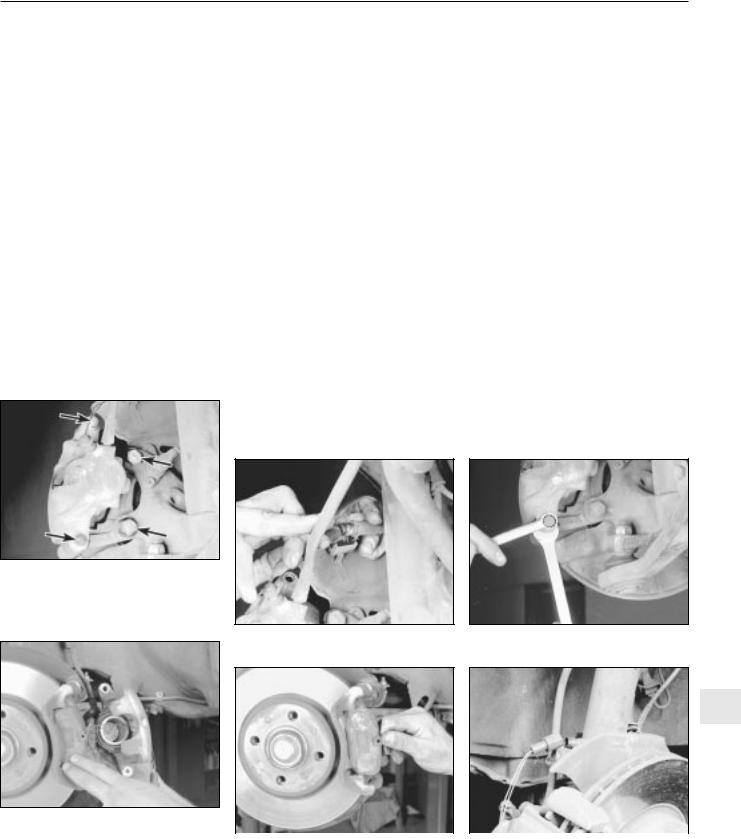
3.5a On 3-Series models, unscrew the caliper mounting bolts (left arrows); right arrows point to the caliper bracket bolts, which should only be removed if you’re removing the brake disc
diagnosed by a dealer service department. Due to the complex nature of this system, all actual repair work must be done by a dealer service department.
3 Disc brake pads - renewal |
2 |
|
|
Warning: Disc brake pads must be renewed on both front wheels or both rear wheels at the same time - NEVER renew the pads on
only one wheel. Also, the dust created by the brake system may contain asbestos, which is harmful to your health. Never blow it out with compressed air, and don’t inhale any of it. An approved filtering mask should be worn when working on the brakes. Do not, under any circumstances, use petroleum-based solvents to clean brake parts. Use brake system cleaner only! When servicing the disc brakes, use only original-equipment or high-quality brand-name pads.
Warning: Brake fluid is poisonous. It is also an effective paint stripper. Refer to the warning at the start of Section 16.
Note: This procedure applies to both the front and rear disc brakes.
1 Remove the cap(s) from the brake fluid reservoir, and syphon off about two-thirds of the fluid from the reservoir. Failing to do this
3.5b Unplug the electrical connector for the brake pad wear sensor (3-Series)
could result in the reservoir overflowing when the caliper pistons are pressed back into their bores.
2Loosen the wheel bolts, raise the front or rear of the vehicle and support it securely on axle stands.
3Remove the front or rear wheels, as applicable. Work on one brake assembly at a time, using the assembled brake for reference if necessary.
4Inspect the brake disc carefully as outlined in Section 5. If machining is necessary, follow the information in that Section to remove the disc, at which time the pads can be removed from the calipers as well.
5Follow the accompanying photos, beginning with illustration 3.5a, for the pad removal procedure. Be sure to stay in order, and read the caption under each illustration.
Note 1: Different types of front calipers are used on 3 and 5-Series models. Illustrations 3.5a to 3.5e are for the front calipers on 3- Series models. Illustrations 3.5f to 3.5m are for the front calipers on 5-Series models. There’s no photo sequence for rear calipers; although slightly different in size, they’re identical in design to the front brake calipers used on 5-Series models. Note 2: Some models may have different numbers and types of anti-squeal shims and other hardware than what is shown in this Chapter. It’s best to note how the hardware is fitted on the vehicle before dismantling, so you can duplicate it on reassembly.
3.5c Hold the guide pins while loosening the caliper mounting bolts (3-Series)
9
3.5d Remove the caliper, brake pad wear |
|
|
|
sensor and inner pad all at the same time |
|
|
|
|
|
|
|
(3-Series), then refit the inner pad on the |
3.5e Remove the outer brake pad |
3.5f On 5-Series models, unplug the |
|
piston and press the piston fully into the |
(3-Series) - to fit the new pads, reverse the |
electrical connector for the brake pad |
|
bore with a C-clamp |
removal procedure |
wear sensor |
|

9•4 Braking system
caliper mounting bolts, then remove the bolts (5-Series)
3.5j Remove the caliper and inner brake pad (5-Series)
3.5m Remove the outer brake pad - to fit the new pads, reverse the removal procedure
6Be sure to inspect the wear sensor(s) (left front wheel only, or left front and right rear wheel). If they’re OK, transfer them from the old pads to the new ones; if they’re worn by abrasion, fit new sensors on the new pads.
7To fit the new pads, reverse the removal procedure. When refitting the caliper, be sure to tighten the mounting bolts to the torque listed in this Chapter’s Specifications.
Warning: Check and if necessary renew the mounting bolts on 3- Series models whenever they are removed. If in doubt, use new bolts.
8 After the job is completed, firmly depress the brake pedal a few times, to bring the pads into contact with the discs. The pedal should
3.5h Prise off the anti-rattle spring |
3.5i Depress the piston with a C-clamp |
|
(5-Series) |
(5-Series) |
|
|
|
|
|
|
|
3.5k Unclip the inner brake pad from the piston (5-Series)
be at normal height above the floor, and firm. Check the level of the brake fluid, adding some if necessary. Check carefully for leaks, and check the operation of the brakes before returning the vehicle to normal service.
9 Avoid heavy braking as far as possible for the first hundred miles or so until the new pads have bedded in.
4 Disc brake caliper - removal, |
4 |
overhaul and refitting |
|
|
|
Warning: Dust created by the brake system may contain asbestos, which is harmful to your health. Never blow it out
with compressed air, and don’t inhale any of it. An approved filtering mask should be worn when working on the brakes. Do not, under any circumstances, use petroleumbased solvents to clean brake parts. Use brake system cleaner only!
Warning: Brake fluid is poisonous. It is also an effective paint stripper. Refer to the warning at the start of Section 16.
Note: If an overhaul is indicated (usually because of fluid leakage), explore all options before beginning the job. Overhauled calipers may be available on an exchange basis, which makes this job quite easy. If you decide to overhaul the calipers, make sure that an
3.5l Hang the caliper out of the way with a piece of wire
overhaul kit is available before proceeding. Always overhaul the calipers in pairs - never overhaul just one of them.
Removal
1Loosen the wheel bolts, raise the front or rear of the vehicle, and place it securely on axle stands. Remove the wheel.
2If you’re just removing the caliper for access to other components, it isn’t necessary to detach the brake line. If you’re removing the caliper for overhaul, disconnect the brake line from the caliper, for preference using a split ring (“brake”) spanner to protect the fitting. Plug the line, to keep contaminants out of the brake system and to prevent losing brake fluid unnecessarily.
3Refer to Section 3 for the front or rear caliper removal procedure - it’s part of the brake pad renewal procedure. Note: The rear caliper is similar in design to the front caliper on 5-series models.
Overhaul
4On all calipers except the front calipers on 3-Series models, remove the circlip for the dust seal (see illustration), then remove the dust boot (see illustration). Before you remove the piston, place a block of wood between the piston and caliper to prevent damage as it is removed.
5To remove the piston from the caliper, apply compressed air to the brake fluid hose connection on the caliper body (see
Braking system 9•5
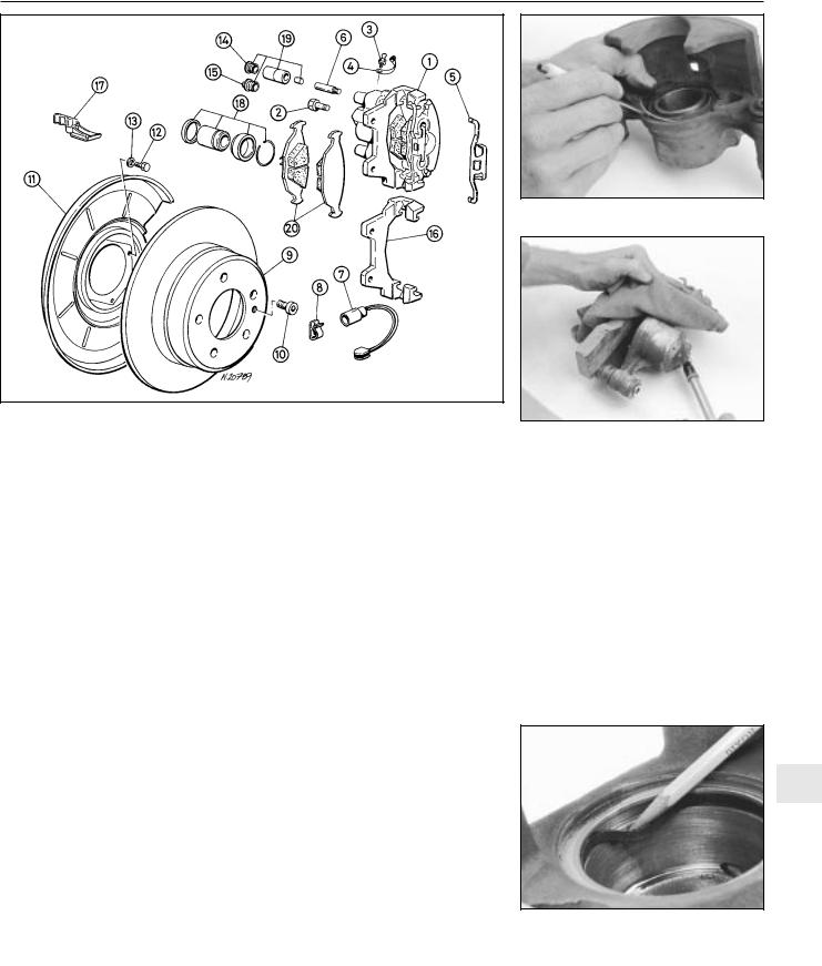
|
4.4a An exploded view of a typical rear caliper assembly (front calipers similar) |
||||
|
|
|
|
|
|
1 |
Caliper assembly |
8 |
Cable clamp |
15 |
Plug |
2 |
Bracket mounting bolt |
9 |
Brake disc |
16 |
Caliper bracket |
3 |
Bleed screw |
10 |
Allen bolt |
17 |
Cable clamp |
4 |
Dust cap |
11 |
Shield |
18 |
Piston seal, piston, dust |
5 |
Anti-rattle spring |
12 |
Bolt |
|
boot and circlip |
6 |
Guide bolt |
13 |
Washer |
19 |
Guide bush repair kit |
7 |
Brake pad wear warning |
14 |
Plug |
20 |
Brake pads |
|
light wire |
|
|
|
|
|
|
|
|
|
|
illustration). Use only low pressure, such as that produced by a foot pump, to ease the piston out of its bore.
Warning: Be careful not to place your fingers between the piston and the caliper, as the piston may come out with some force. If
you’re working on a front caliper of a 3- Series model, remove the dust boot.
6Inspect the mating surfaces of the piston and caliper bore wall. If there is any scoring, rust, pitting or bright areas, renew the complete caliper unit.
7If these components are in good condition, remove the piston seal from the caliper bore using a wooden or plastic tool (see illustration). Metal tools may damage the cylinder bore.
8Remove the caliper guide pins or bolts and remove the rubber dust boots.
9Wash all the components using methylated spirit or brake system cleaner.
10Using the correct overhaul kit for your vehicle, reassemble the caliper as follows.
11Dip the new rubber seal in clean brake fluid, and refit it in the lower groove in the caliper bore, making sure it isn’t twisted.
12On all calipers except the front calipers of 3-Series models, coat the walls of the caliper
bore and the piston with clean brake fluid, and refit the piston at this time. Do not force the piston into the bore, but make sure that it is squarely in place, then apply firm (but not excessive) pressure to refit it. Fit the new rubber dust boot and the retaining ring.
13On the front calipers of 3-Series models, coat the piston with clean brake fluid, and stretch the new dust boot over the bottom of the piston. Hold the piston over the caliper bore, and insert the rubber flange of the dust boot into the upper groove in the bore. Start with the furthest side from you, and work your way around towards the front until it is completely seated. Push the piston into the caliper bore until it is bottomed in the bore, then seat the top of the dust boot in the groove in the piston.
14Lubricate the sliding surfaces of the guide pins or bolts with silicone-based grease (usually supplied in the kit), and push them into the caliper. Refit the dust boots.
Refitting
15 Refit the caliper by reversing the removal procedure (see Section 3).
Warning: Check and if necessary renew the mounting bolts on 3- Series models whenever they are removed. If in doubt, use new bolts.
4.4b Remove the circlip for the dust seal
4.5 With the caliper padded to catch the piston, use low pressure compressed air to force the piston out of its bore - make sure your fingers are not between the piston and the caliper
16 If the hose was disconnected from the caliper, bleed the brake system (see Section 16).
5 Brake disc - inspection, |
2 |
removal and refitting |
|
|
|
Note: This procedure applies to both the front and rear brake discs. Brake discs should always be renewed or refinished in pairs (both front or both rear discs) even if only one is damaged or defective.
9
4.7 Remove the piston seal from the caliper bore using a wooden or plastic tool (metal tools may damage the
cylinder bore)

9•6 Braking system
5.2 Remove the caliper mounting bracket bolts (arrowed) and remove the bracket
Inspection
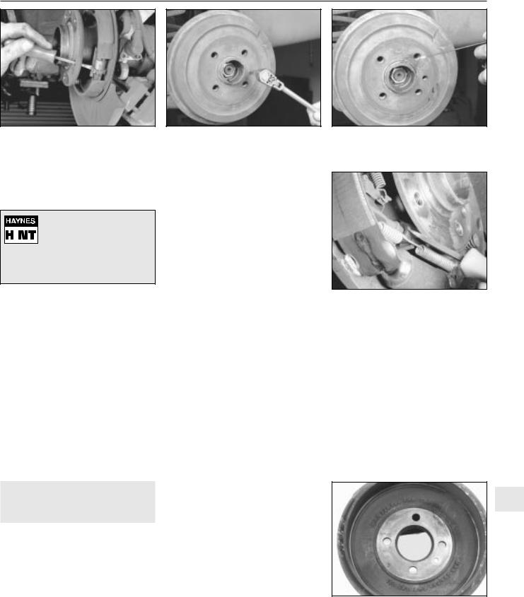
1Loosen the wheel bolts, raise the vehicle and support it securely on axle stands. Remove the wheel, and refit three bolts to hold the disc in place. If the rear brake disc is being worked on, release the handbrake.
2Remove the brake caliper as outlined in Section 4. It is not necessary to disconnect the brake hose. After removing the caliper, suspend it out of the way with a piece of wire. Remove the caliper mounting bracket (see illustration).
3Inspect the disc surface for scoring, cracks or other damage. Light scratches and shallow grooves are normal after use, and are not usually detrimental to brake operation, but deep scoring requires disc removal and
5.4b Using a swirling motion, remove the glaze from the disc surface with sandpaper or emery cloth
5.3 The brake pads on this vehicle were obviously neglected, as the backing plate cut deep grooves into the disc - wear this severe means the disc must be renewed
renewal, or (if possible) refinishing by a specialist. If a disc is cracked it must be renewed. Be sure to check both sides of the disc (see illustration). If severe vibration has been noticed during application of the brakes, the discs may be warped (excessive run-out). If the vehicle is equipped with the Anti-lock Braking System (ABS), do not confuse vibration caused by warped discs with normal operation of the ABS. It is quite normal for some vibration to be felt through the pedal when the system is working.
4 To check disc run-out, place a dial indicator at a point about 13 mm from the outer edge of the disc (see illustration). Set the indicator to zero, and rotate the disc. The indicator reading should not exceed the specified
5.5 The disc thickness can be checked with a micrometer
5.4a To check disc run-out, mount a dial indicator as shown, and rotate the disc
allowable run-out limit. If it does (and if the run-out is not due to wheel bearing wear), the disc should be renewed or (if possible) refinished by a specialist. Note: It is recommended that the discs be resurfaced regardless of the dial indicator reading, as this will impart a smooth finish and ensure a perfectly flat surface, eliminating any vibration felt through the brake pedal or other undesirable symptoms related to questionable discs. At the very least, if you elect not to have the discs resurfaced, remove the glazing from the surface with emery cloth or sandpaper, using a swirling motion (see illustration).
5 It is absolutely critical that the disc not be machined to a thickness less than that specified. The minimum wear (or discard) thickness is stamped into the hub of the disc. The disc thickness can be checked with a micrometer (see illustration).
Removal
6 Remove the disc retaining screw (see illustration) and remove the disc from the hub (see illustration). If the disc is stuck to the hub, spray a generous amount of penetrating oil onto the area between the hub and the disc (see illustration) and allow a few minutes for it to loosen the rust between the two components. If a rear disc still sticks, insert a thin, flat-bladed screwdriver through the hub flange, rotate the starwheel on the handbrake
5.6a Remove the disc retaining screw . . .
5.6b . . . and remove the disc from the hub
5.6c If the disc is stuck to the hub, spray some penetrating oil onto the area between the hub and the disc, and give the oil a few minutes to separate the two parts
Braking system 9•7
5.6d If a rear disc still sticks to the hub, insert a thin, flat-bladed screwdriver through the hub flange, rotate the starwheel on the handbrake adjusting screw, and contract the handbrake shoes (disc removed for clarity)
adjusting screw and contract the handbrake shoes (see illustration).
If the front disc is stuck, on
 some discs it is possible to
 thread two or three bolts into the holes provided and
tighten them. Alternate between the bolts, turning them a couple of turns at a time, until the disc is free.
Refitting
7 Ensure that the disc is completely clean before refitting. If penetrating oil was used to remove the disc, make sure that no trace of this is present. Place the disc on the hub, and refit the disc retaining screw. Tighten the screw securely.
8 Refit the caliper mounting bracket (if removed), brake pads and caliper (see Sections 3 and 4). Tighten all fasteners to the torques listed in this Chapter’s Specifications.
9Refit the wheel, then lower the vehicle to the ground. Depress the brake pedal a few times to bring the brake pads into contact with the disc.
10Adjust the handbrake shoes, if necessary (Section 11).
11Check the operation of the brakes carefully before returning the vehicle to normal service.
6 Drum brake shoes - renewal 2
Warning: Brake shoes must be renewed on both wheels at the same time - never renew the shoes on only one wheel. Also,
the dust created by the brake system may contain asbestos, which is harmful to your health. Never blow it out with compressed air, and don’t inhale any of it. Always wear an approved filtering mask when servicing the brake system. Do not, under any
6.2a Removing the drum retaining screw
circumstances, use petroleum-based solvents to clean brake parts. Use brake system cleaner only.
Caution: Whenever the brake shoes are renewed, new return and hold-down springs and new automatic adjuster thermo-clips
should also be fitted. Due to the continuous heating/cooling cycle to which the springs are subjected, they may lose their tension over a period of time, allowing the shoes to drag on the drum, and wear at a much faster rate than normal. When fitting new brake shoes, use only original-equipment or high-quality brand name parts.
Note 1: All four rear brake shoes must be renewed at the same time, but to avoid mixing up parts, work on only one brake assembly at a time. Some rear brake components are different for left and right-hand sides, so don’t mix them up.
Note 2: If the wheel cylinder is found to be leaking or otherwise defective, renew it after removing the brake shoes. This is simply a matter of disconnecting the hydraulic line and unbolting the cylinder from the backplate. Attempting to overhaul a leaking cylinder is unlikely to be satisfactory, even if spare parts are available.
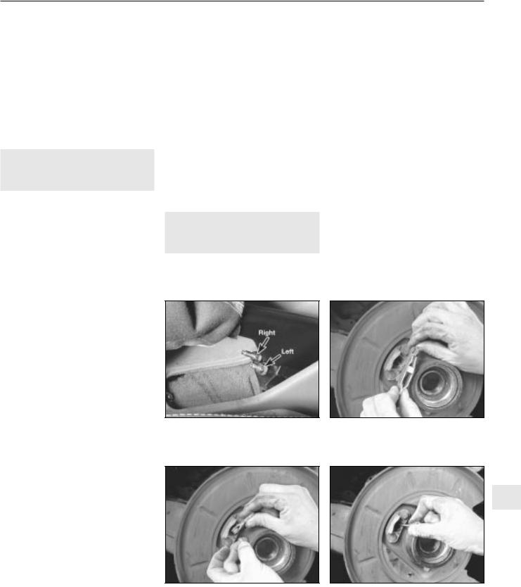
1 Chock the front wheels, then loosen the rear wheel bolts, raise the rear of the vehicle and place it securely on axle stands. Remove the rear wheels and release the handbrake.
2 Remove the drum retaining screw (see illustration) and remove the drum. If the drum is stuck to the hub, spray the area between the hub and the drum with penetrating oil (see illustration). If the drum still won’t come off, the shoes have probably worn ridges into the drum, and will have to be retracted. Insert a narrow flat-bladed screwdriver through one of the holes in the hub flange (see illustration) and back off the adjuster wheel until the drum can be removed.
3 Inspect the drum for cracks, score marks, deep scratches and hard spots, which will appear as small discoloured areas. If the hard spots can’t be removed with emery cloth or if any of the other conditions exist, the drum must be taken to a specialist to have the drum resurfaced. Note: Professionals recommend
6.2b If the drum is stuck to the hub, apply penetrating oil around the hub/drum area, and give it a few minutes to loosen up any rust
6.2c If the brake shoes have worn a groove in the drum and it won’t come off, insert a thin flat-bladed screwdriver through one of the wheel bolt holes in the flange, and loosen the automatic adjuster mechanism (for the sake of clarity, the drum has already been removed in this photo, and the screwdriver is being inserted underneath the flange instead of though a wheel bolt hole)
resurfacing the drums whenever a brake job is done. Resurfacing will eliminate the possibility of out-of-round drums. If the drums are worn so much that they can’t be resurfaced without exceeding the maximum allowable diameter (which is cast into the drum) (see illustration), then new ones will be required. At the very least, if you elect not to have the drums resurfaced, remove the glazing from the surface with emery cloth or sandpaper, using a swirling motion.
9
6.3 The maximum allowable inside diameter of the drum is cast into the drum
9•8 Braking system
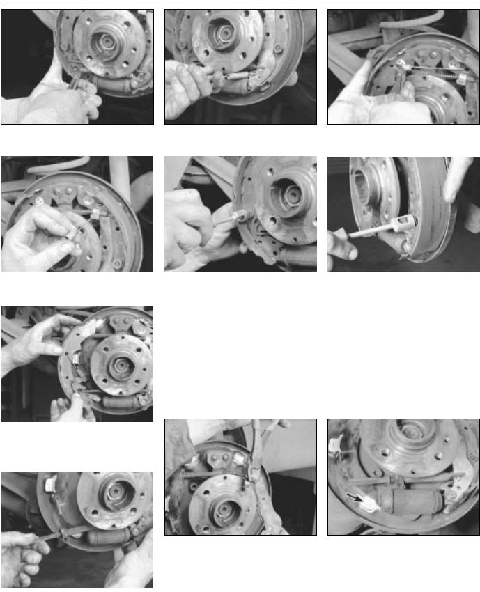
6.4a Unhook the lower return spring from |
6.4b . . . |
then unhook it from the rear shoe |
6.5a Unhook the upper return spring from |
||
the front shoe . . . |
|
and remove it |
the front shoe . . . |
||
|
|
|
|
|
|
|
|
|
|
|
|
|
|
|
|
|
|
6.5b . . . then unhook it from the rear shoe |
6.6a Remove the front shoe hold- |
6.6b . . . and the rear shoe hold- |
|||
and remove it |
down spring . . . |
down spring |
|||
|
|
4 Unhook and remove the lower return spring |
adjuster wheel) be renewed whenever new |
||
|
|
||||
|
|
(see illustrations). |
shoes are fitted. Turn the adjuster wheel so |
||
|
|
5 Unhook and remove the upper return spring |
that the assembly is at its shortest position |
||
|
|
(see illustrations). |
ready for refitting. |
||
|
|
6 Remove the front and rear brake shoe hold- |
9 Disconnect the handbrake cable from the |
||
|
|
down springs (see illustrations). |
handbrake lever, and remove the rear shoe |
||
|
7 |
Remove the front shoe (see illustration). |
(see illustration). |
||
|
|
8 Remove the adjuster assembly (see |
10 Refitting is basically the reverse of |
||
|
|
illustration). Clean the adjuster and make |
removal, but note the following points. |
||
|
|
sure that the adjuster wheel moves freely on |
11 Apply a smear of high-temperature brake |
||
|
|
the threads. It is recommended that the |
grease to the backing plate (see illustration). |
||
|
|
thermo-clip (the spring clip next to the |
Be careful not to get grease onto the |
||
|
|
|
|
|
|
|
|
|
|
|
|
6.7 Remove the front shoe, automatic |
|
|
|
||
adjuster lever and spring as an assembly, |
|
|
|
||
then remove the lever and spring, and set |
|
|
|
||
them aside for attachment to the new shoe |
|
|
|
||
|
6.9 To disconnect the handbrake cable |
6.11 Before you fit the new shoes, apply |
|
|
from the handbrake lever, pull on the plug |
some high-temperature brake grease to |
|
|
at the end of the cable, and detach the |
the friction surfaces where the inner edge |
|
|
cable from the bracket on the upper end of |
of the shoe slides on the brake backing |
|
|
the lever (diagonal cutting pliers are being |
plate - when you refit the automatic |
|
|
used here because they grip the cable |
adjuster mechanism, make sure each end |
|
6.8 Remove the automatic adjuster |
|||
well, but care must be taken not to nick |
engages properly with its respective notch |
||
assembly |
the cable) |
in the brake shoe |
Braking system 9•9
6.13a Refit the automatic adjuster lever first - make sure it’s properly engaged with the notch in the front end of the
adjuster mechanism . . .
friction surfaces of the brake shoes or drums.
12 Make sure the adjuster assembly is properly engaged with its respective notch in the handbrake lever.
13When refitting the automatic adjustment mechanism, fit the lever on the shoe first (see illustration), then hook the lower end of the spring onto the lever and the upper end into its hole in the front shoe (see illustration).
14When you’re done, the brake assembly should look like this (see illustration). Now proceed to the other brake.
15When you’re done with both brakes, refit the brake drums.
16If the wheel cylinder was renewed (see Note 2), bleed the hydraulic system as described in Section 16.
17Depress the brake pedal repeatedly to actuate the self-adjusting mechanism. A clicking sound will be heard from the brake drums as the adjusters take up the slack.
18Check the handbrake adjustment (Section 11).
19Refit the wheels and bolts. Lower the vehicle to the ground, and tighten the wheel bolts to the torque listed in the Chapter 1 Specifications. Check the operation of the brakes carefully before driving the vehicle in traffic.
7 Master cylinder - |
3 |
removal and refitting |
|
|
|
Warning: Brake fluid is poisonous. It is also an effective paint stripper. Refer to the warning at the start of Section 16.
Note: Although master cylinder parts and overhaul kits are available for most models, we recommend fitting a new or overhauled master cylinder complete. It will take you more time to overhaul the master cylinder than to renew it, and you can’t even determine whether the master cylinder is in good enough condition to overhaul it until you have dismantled it. You may very well find that it
6.13b . . . then hook the lower end of the spring onto the lever as shown; stretch the spring, and hook the upper end into its hole in the handbrake shoe
can’t be overhauled because of its internal condition.
Removal
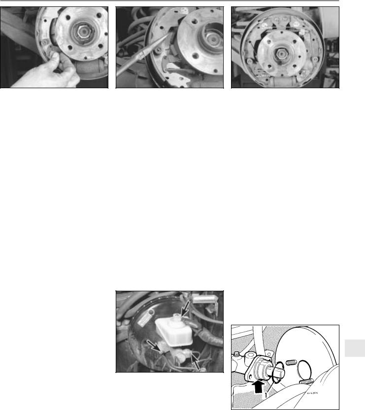
1 The master cylinder is connected to the brake vacuum servo, and both are attached to the bulkhead, located on the left-hand side of the engine compartment (see illustration).
2Remove as much fluid as you can from the reservoir with a syringe.
3Place rags under the line fittings, and prepare caps or plastic bags to cover the ends of the lines once they are disconnected.
Caution: Brake fluid will damage paint. Cover all body parts, and be careful not to spill fluid during this procedure.
4Loosen the union nuts at the ends of the brake lines where they enter the master cylinder. To prevent rounding off the flats on these nuts, a split ring (“brake”) spanner, which wraps around the nut, should be used.
5Pull the brake lines away from the master cylinder slightly, and plug the ends to prevent dirt contamination and further fluid loss.
6Disconnect any electrical connectors at the
master cylinder, then remove the nuts
7.1 To remove the master cylinder, unplug the electrical connector (top arrow), disconnect the brake fluid hydraulic line fittings (lower right arrow, other fitting not visible in this photo) and remove the two master cylinder mounting nuts (lower left arrow, other nut not visible in this photo) - 5-Series master cylinder shown, 3-Series similar
6.14 When you get everything back together, this is how it
should look!
attaching the master cylinder to the brake servo. Pull the master cylinder off the studs, and lift it out of the engine compartment. Again, be careful not to spill fluid as this is done. Discard the old O-ring (see illustration) between the master cylinder and the servo unit.
Warning: The O-ring should always be renewed. A faulty O- ring can cause a vacuum leak,
which can reduce braking performance and cause an erratic idle.
Bleeding procedure
7Before fitting a new or overhauled master cylinder, it should be bled on the bench. Because it will be necessary to apply pressure to the master cylinder piston and, at the same time, control flow from the brake line outlets, it is recommended that the master cylinder be mounted in a vice. Use a vice with protected jaws, and don’t clamp the vice too tightly, or the master cylinder body might crack.
8Insert threaded plugs into the brake line outlet holes. Tighten them down so that there will be no air leakage past them, but not so tight that they cannot be easily loosened.
9Fill the reservoir with brake fluid of the recommended type (see “Lubricants, fluids and capacities” in Chapter 1).
10Remove one plug, and push the piston assembly into the master cylinder bore to
9
7.6 Always renew the O-ring (1) - groove arrowed - between the master cylinder and the brake servo
9•10 Braking system
expel the air from the master cylinder. A large Phillips screwdriver can be used to push on the piston assembly.
11To prevent air from being drawn back into the master cylinder, the plug must be refitted and tightened down before releasing the pressure on the piston assembly.
12Repeat the procedure until brake fluid free of air bubbles is expelled from the brake line outlet hole. Repeat the procedure with the other outlet hole and plug. Be sure to keep the master cylinder reservoir filled with brake fluid, to prevent the introduction of air into the system.
13High pressure is not involved in the bench bleeding procedure, so the plugs described above need not be refitted each time the piston is released, if wished. Instead, before releasing the piston, simply put your finger tightly over the hole to keep air from being drawn back into the master cylinder. Wait several seconds for brake fluid to be drawn from the reservoir into the piston bore, then depress the piston again, removing your finger as brake fluid is expelled. Be sure to put your finger back over the hole each time before releasing the piston, and when the bleeding procedure is complete for that outlet, refit the plug and tighten it up before going on to the other port.
Refitting
14Refit the master cylinder (together with a new O-ring) over the studs on the brake servo, and tighten the mounting nuts only finger-tight at this time.
15Thread the brake line fittings into the master cylinder. Since the master cylinder is still a bit loose, it can be moved slightly in order for the fittings to thread in easily. Do not strip the threads as the fittings are tightened.
16Tighten the brake fittings securely, and the mounting nuts to the torque listed in this Chapter’s Specifications.
17Fill the master cylinder reservoir with fluid, then bleed the master cylinder (only if the cylinder has not already been bled) and the brake system as described in Section 16.
18To bleed the cylinder on the vehicle, have an assistant pump the brake pedal several
times and then hold the pedal to the floor. Loosen the fitting nut to allow air and fluid to escape, then tighten the nut. Repeat this procedure on both fittings until the fluid is clear of air bubbles. Test the operation of the brake system carefully before returning the vehicle to normal service.
8 Brake vacuum servo - |
3 |
check, removal and refitting |
Operating check
1Depress the brake pedal several times with the engine off, until there is no change in the pedal travel.
2Depress and hold the pedal, then start the engine. If the pedal goes down slightly, operation is normal.
Airtightness check
3Start the engine, and turn it off after one or two minutes. Depress the brake pedal several times slowly. If the pedal goes down further the first time but gradually rises after the second or third depression, the servo is airtight.
4Depress the brake pedal while the engine is running, then stop the engine with the pedal depressed. If there is no change in the pedal travel after holding the pedal for 30 seconds, the servo is airtight.
Removal and refitting
5 Dismantling the vacuum servo requires special tools, and cannot be performed by the home mechanic. If a problem develops, it is recommended that a new unit be fitted.
6Remove the master cylinder as described in Section 7.
7Disconnect the vacuum hose from the brake servo.
8Working in the passenger compartment, remove the glovebox and lower left-hand trim panels.
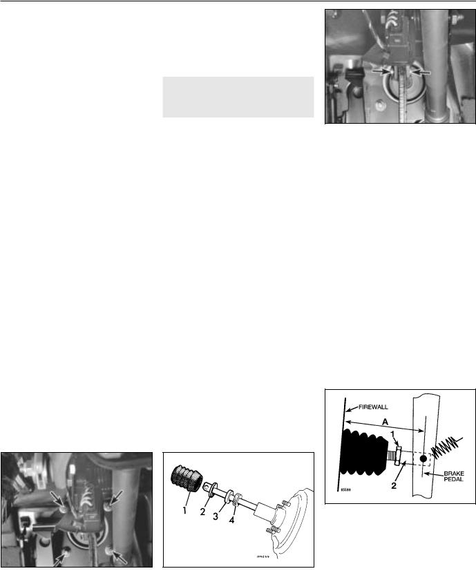
9Remove the clip and clevis pin to disconnect the pushrod from the cross-shaft lever (right-hand-drive models) or brake pedal
8.9 Disconnect the brake pedal return spring, then remove the clip and clevis pin (arrows) to disconnect the pushrod from the brake pedal (left-hand-drive models)
(left-hand-drive models) (see illustration). On left-hand-drive models, also disconnect the brake pedal return spring.
10 Remove the four mounting nuts (see illustration) and withdraw the servo unit from the engine compartment.
11 Inspect the small foam filter (see illustration) inside the rubber boot on the pushrod. If the filter is clogged, it may affect the servo’s performance. To clean the filter, wash it in a mild soapy solution. If it’s still dirty, renew it.
12Refitting is the reverse of the removal procedure. Tighten the brake servo mounting nuts to the torque listed in this Chapter’s Specifications. Before you slide the boot into place over the servo pushrod air filter, make sure the notches in the filter offset the notches in the damper by 180 degrees.
13On 3-Series models, adjust the basic setting of the pushrod’s threaded clevis until the dimension is correct (see illustration). When the basic setting is correct, tighten the locknut, then adjust the brake pedal travel and
8.10 Remove the four mounting nuts |
8.11 An exploded view of a typical servo |
|
(arrows) and withdraw the servo unit from |
pushrod assembly |
|
the engine compartment |
1 Boot 2 Holder 3 Damper 4 Air filter |
|
(left-hand-drive model shown) |
||
|
8.13 On 3-Series models, adjust dimension A (the distance between the middle of the brake lever and the bulkhead/”firewall”) by loosening the locknut (1) at the pushrod clevis (2) and turning the threaded part of the pushrod until dimension A matches the dimension listed in this Chapter’s Specifications. When the basic setting is correct, tighten the locknut, then adjust the brake pedal height and the stop-light switch
Braking system 9•11
the stop-light switch (see Section 13). Note:
On right-hand-drive models, the brake pedal in on the right-hand side of the vehicle, and is connected to the left-hand side by a crossshaft. The adjustment is carried out on the pushrod at the left-hand side, but the dimension is measured at the pedal on the right-hand side.
14On 5-Series models, adjust the brake pedal height and the stop-light switch (see Section 13).
15Refit the master cylinder (see Section 7) and attach the vacuum hose.
16Carefully test the operation of the brakes before returning the vehicle to normal use
9 Hydraulic brake servo - |
3 |
description, removal and |
|
refitting |
Warning: Brake fluid is poisonous. It is also an effective paint stripper. Refer to the warning at the start of Section 16.
Description
1On 5-Series E28 (“old-shape”) models, a hydraulic brake servo system is fitted. The servo unit, located between the brake pedal (left-hand-drive) or cross-shaft lever (right- hand-drive) and the master cylinder, is operated by hydraulic pressure generated by the power steering pump. When the engine is running, the power steering pump supplies hydraulic pressure to a power flow regulator/ accumulator. The regulator/accumulator stores and regulates the pressure to the hydraulic brake servo. When you press the brake pedal, the pressure in the servo helps actuate the master cylinder, reducing pedal effort.
2The hydraulic brake servo cannot be overhauled; if it fails, a new one must be fitted. Testing the system requires special tools, so even fault diagnosis is beyond the scope of the home mechanic. If the system fails, take it to a dealer service department or other qualified garage for repairs.
drive models). On left-hand-drive models, also disconnect the pedal return spring.
7Prise off the retaining clip, and disconnect the pushrod from the brake pedal (see illustration 8.9) or cross-shaft lever.
8Remove the four mounting nuts and
remove the brake servo (see illustration 8.10).
9Refitting is the reverse of removal. Tighten the hydraulic lines to the torque listed in this Chapter’s Specifications. Note: Don’t try to tighten these fittings without a torque wrench. If they’re loose, they can leak, which can affect system operation; if they’re tight, they can be damaged, and they’ll also leak. You’ll need a crowfoot-type split ring (“brake”) attachment for your torque wrench to tighten the fittings properly.
10When you’re done, bleed the brake hydraulic system (Section 16) and adjust the brake pedal travel and the stop-light switch (see Section 13).
10 Handbrake cable(s) - renewal 2
1 Peel back the boot at the base of the handbrake lever, and remove the handbrake cable adjusting nut (see illustration) which also secures the cable to the handbrake lever.
10.1 Peel back the handbrake lever boot and remove the relevant handbrake cable adjusting nut (both arrowed)
Removal and refitting
3With the engine off, discharge the hydraulic accumulator by depressing the brake pedal
20times or more.
4Remove the master cylinder (see Section 7).
5Clean the area around the return and supply line fittings, then disconnect them. Plug the lines, to prevent dirt from entering the system, and to prevent further fluid loss.
Caution: Even a particle of dirt can damage the servo, so be extremely careful to prevent dirt from entering the system while the lines are disconnected.
6Working from inside the passenger compartment, remove the lower left trim panels above the brake pedal (left-hand-drive models) or glovebox and trim (right-hand-
10.4b . . . then remove the pin securing the cable to the inner cam, and remove the inner cam
There are two cables - one for each rear wheel - and a nut for each cable. On some models, it may be necessary to remove the centre console completely for access.
2Raise the vehicle and support it securely on axle stands.
3Remove the rear brake drum (see Section 6) or rear brake disc (see Section 5).
4On rear drum models, unhook the handbrake cable from the lever on the rear brake shoe (see Section 6). On rear disc models, remove the handbrake shoes and the actuator (see Section 12) and unhook the handbrake cable from the actuator (see illustrations).
5On rear drum models, pull the cable and cable conduit (tube) out of the back of the brake backplate, then detach the cable conduit from the cable clips on the back of the trailing arm (it’s easier to pull out the old cable, and fit the new cable, with the conduit straight instead of curved). On rear disc models, it’s unnecessary to detach the cable conduit from the brake backplate, but it’s a good idea to detach the conduit from the clips and guides securing it to the trailing arm, to take some of the bend out of the conduit.
6Working from the wheel end of the cable conduit, pull the cable out of the conduit (see illustration).
7Lubricate the new cable with multi-purpose grease, then insert it into the cable conduit
10.4a To detach the handbrake cable from the handbrake actuator on models with rear disc brakes, pull on the outer cam and disconnect it from the inner cam . . .
9
10.6 Pull the cable out of its conduit; before you refit the new cable, be sure to lubricate it with multi-purpose grease