

6 Protocol content
6.1 Title and goal of the laboratory work.
6.2 Results of home task.
6.3 Carrying out results of the laboratory tasks with the tables and graphs.
6.4. Conclusions of the work.
Appendix to the lab №12 Graphical representation of the expected results
The level of crosstalk on the near- (Pn) and far-end (Pf) and the maximal value of the signal/noise ratio SNR depending on the length of ADSL are shown on the fig. D.1 and D.2 (50-pair concentric layer cable ТПП with the core diameter 0.64 mm; number of influenced pair - 29; number of influencing pair – 25; PSD of white noise is minus 140 dBm/Hz; ADSL2+)
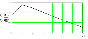
Figure D.1 – The level of crosstalk on the near- (Pn) and far-end (Pf) depending on the length of ADSL
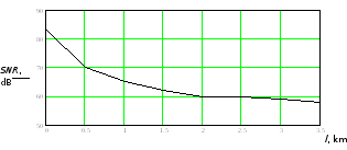
Figure D.2 – The maximal value of the signal/noise ratio SNR depending on the length of ADSL
Laboratory work № 13 Title: Research of the transmission rate dependence in digital subscriber line with parallel operation of transmission systems of xDSL on loading scripts and cable characteristics 1 Aim: Research of the transmission rate dependence in digital subscriber line xDSL with parallel it operation on loading scripts, core cable diameter, subscriber line length and the noise level
2 Key positions
2.1 Key concepts
Signal attenuation means decreasing of power of sinusoidal signal during its transmission inside of distribution medium.
Transitive attenuation is an attenuation of sinusoidal signal at its transit from influencing circuit to influenced one
Transitive attenuation on near end is an attenuation of sinusoidal signal at transit from near end of influencing circuit to near end of influenced one with the condition of matching both ends in the circuit.
Transitive attenuation on far end is an attenuation of sinusoidal signal at transit from near end of influencing circuit to far end of influenced one with the condition of matching both ends in the circuit.
Loading script is a concrete variant of placing the set of DSL into multipair cable.
2.2 Evaluation of dsl potential characteristics at parallel work on high-capacity telephone cables.
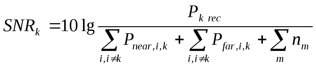
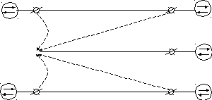
One of the main factors which limit the speed and distance of transmission in subscriber lines are transitive noises, appeared at parallel work of DSL in multipair telephone cables. The algorithm of calculation transitive influences between DSL are shown on figure 2.1 where shown two influencing DSL (DSLi and DSLj) and one influenced DSL (DSLk). Power of incoming signal at the input of i-th SL is Pi trans. On the input of DSLk receiver comes attenuated useful signal with power Pk rec and transitive noises (from near Pnear i,k , Pnear j,k and far Pfar,i,k и Pfar,j,k ends) caused by transmitting signals DSLi и DSLj .
Signal – noise ratio at the input of receiving device DSL is:
 ,
,
where
![]()
PSD – dependence of signal on frequency at the output of transmitter of k-th DSL;
H – amplitude-frequency characteristic of SL (communication channel);
![]() –sum
of other noises, acting on the input of receiving device DSLk
.
–sum
of other noises, acting on the input of receiving device DSLk
.
Pi
tran
DSLi
Pi
tran
Pfar
i,k
i
Pnear
i,k
Pk
rec
k
DSLk
Pj
tran
Pfar
j,k
Pnear
j,k
Pk
tran
DSLj
Pj
tran
j
F
Values Pnea i,k и Pfar i,k can be defined by analogy accordingly to formulas, where H2(f) is substituted frequency functions of transitive characteristics between i-th and и k-th SL on near and far end Hnear i,k(f) и Hfar i,k (f) accordingly:
![]()
In accordance to model of electromagnetic compatibility it is possible to calculate acceptable lengths of SL and their transmission rates into upstream and downstream directions along DSL at different variants of xDSL equipment, loading, level of noise, number of pairs, diameter of core, using of homogeneous and non-homogeneous cables.
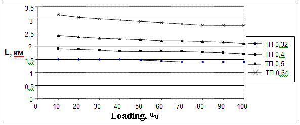
In the Figure 2.2, 2.3 are shown examples of calculations (with the help of program «xDSL-Liner») the maximum length ADSL2+ line at the using 10-pair ТП cables with bunchy twisting of core where diameters of wire are 0,32 mm; 0,4 mm; 0,5 mm and 0,64 mm for different types of white noise at the input of receiver. It also depends on percent of cable pairs using for transmitting of ADSL2+.
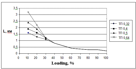
а) White noise equals minus 140 dBm/Hz
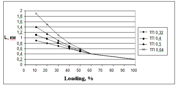
b) White noise equals minus 120 dBm/Hz
c) White noise equals minus 100 dBm/Hz
Figure 2.2 Accessible length of ADSL2+ line for rate 19648 kbps for upstream and 928 kbps for downstream, direction at using of 10-pair TП cable and white noise 140, 120, 100 dBm/Hz which depend on percent of loading by cable at ADSL2+
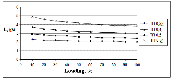
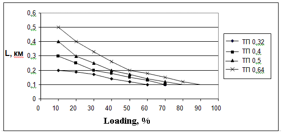
а) White noise equals minus 140 dBm/Hz
b) White noise equals minus 120 dBm/Hz
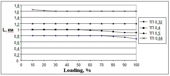
c) White noise equals minus 100 dBm/Hz
Figure 2.3 Accessible length of ADSL2+ line for rate 19648 kbps for upstream and 928 kbps for downstream, direction at using of 10-pair TП cable and white noise 140, 120, 100 dBm/Hz which depend on percent of loading by cable at ADSL2+