

6 Protocol content
6.1 Title and goal of the laboratory work.
6.2 Results carried out in homework.
6.3 Dependency graphs based on performance carried out results ss. 5.2 - 5.4 of laboratory work.
6.4. Carrying out results of the individual tasks in accordance with s. 5.5.
6.5. Conclusions of the work.
Appendix to the lab № 11 Graphical representation of the expected results
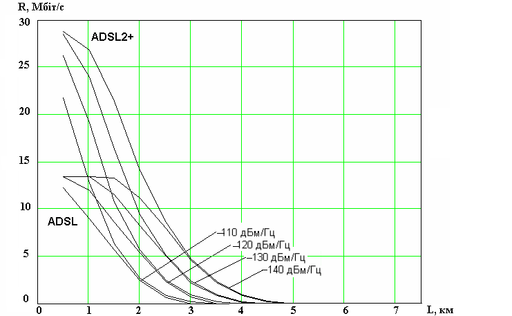
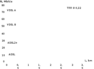
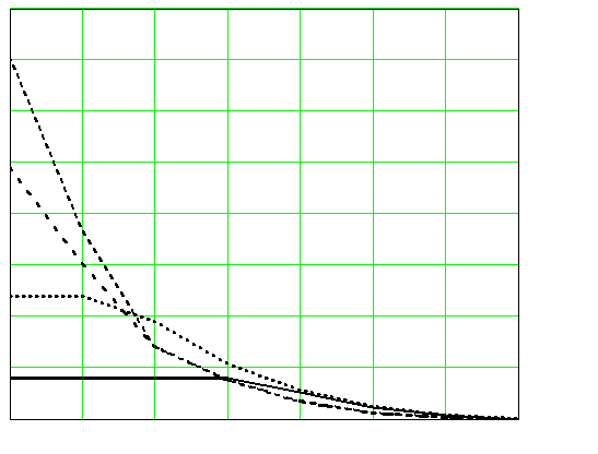
The transmission rate downstream depending on the length of the line TП cable with the core diameter 0.32 mm and 0.4 mm for the various PSD interferences at the receiver input ADSL and ADSL2 + are shown at Fig. D.1.
R,
Мbit/s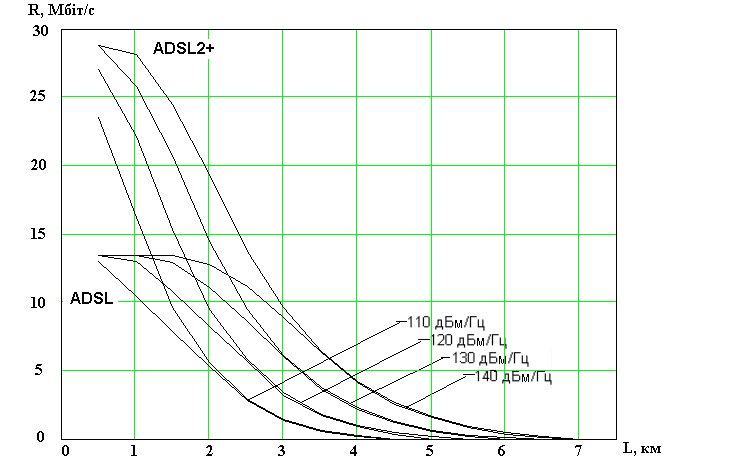
а
R,
Мbit/s
R,
бит /с
b
 )
ТП 0.4
mm
)
ТП 0.4
mm
Figure D.1 – The transmission rate downstream depending on the length of the line TП cable with the core diameter 0.32 mm and 0.4 mm for the various PSD interferences at the receiver input ADSL and ADSL2 +
The transmission rate downstream depending on the length of the line TП cable with the core diameter 0.5 mm and 0.64 mm for the various PSD interferences at the receiver input ADSL and ADSL2 + are shown at Fig. D.2.
R,
Мbit/s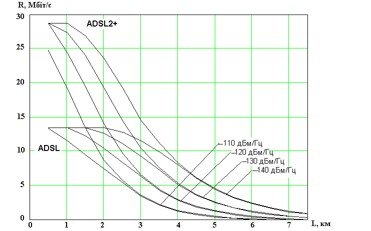
R,
Мbit/s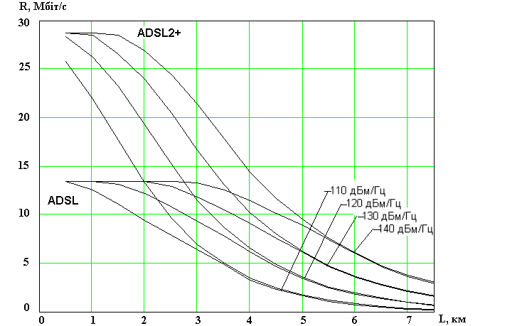
b) ТП 0.64 mm
Figure D.2 – The transmission rate downstream depending on the length of the line TП cable with the core diameter 0.5 mm and 0.64 mm for the various PSD interferences at the receiver input ADSL and ADSL2 +
The transmission rate downstream depending on the length of the line TП cable with the core diameter 0.32 mm for the PSD interferences (minus 120 dBm/Hz) and the transmission rate downstream depending on the PSD interferences (minus 120 dBm/Hz) for the length of ТП cable 2.5 km with the core diameter 0.32 mm are shown in Fig. D.3.
а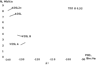 )
)
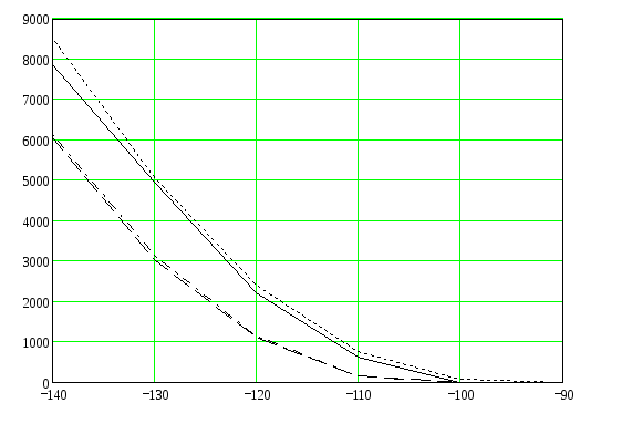
Figure D.3 – The transmission rate depending on a) length of cable b) PSD interferences
Laboratory work № 12
Title: Research of the digital subscriber line xDSL parameters with parallel operation of transmission systems xDSL, depending on their location in the multipair (large capacity) cable, cable length and noise level
1 Objectives: Research of the transmission rate dependence and crosstalk in the digital subscriber lines (DSL) with parallel operation xDSL systems on it relative position in multipair (large capacity) cable, line length and the noise level
2.1 Parameters of the relative influence
The crosstalk attenuation is an attenuation of a sinusoidal signal at the transition from influencing circuit to the exposed to an influence circuit.
The near-end crosstalk attenuation is an attenuation of a sinusoidal signal at the transition from near-end influencing circuit to the near-end exposed to influence circuit on conditions that circuits are matched at the ends.
The matched load is a load, whose parameters correspond to the reception on it greatest power, load lines, where the line is no reflected wave.
The far-end crosstalk attenuation is an attenuation of a sinusoidal signal at the transition from near-end influence circuit to the far-end exposed to influence circuit on conditions that circuits are matched at the ends.
Immunity between the circuits at the far-end (immunity) - attenuation (crosstalk) sinusoidal signal at the transition from the far-end of the influencing circuit to the far-end of the exposed to influence circuit, on conditions that circuits are matched at the ends.
Immunity between the circuits is defined as the difference between the signal level at the end of the influencing circuit and the noise level at exposed to influence circuit.
The attenuation of the asymmetry is an attenuation of a sinusoidal signal at the transition from an artificial circuit formed by wires of cable and the "ground" in working pair cable.
Mutual influence in the cable caused by electromagnetic coupling between the pairs. The level of interference occurring within the cable is determined by the crosstalk between pairs. Distinguish between near-end crosstalk ratio А0, at the far-end of Аl and immunity at the far-end Аi.
Fig. 2.1 shows a model of transitional influences between pairs of the cable. Vertical dashed lines indicate the two ends of the cable.
The pair connected to the generator is influencing, while the pair connected to the ends of the load is one exposed to influence. End of the pair which is connected to pair of generator is near-end. End of the cable pairs which are connected to the load Rl is the far-end. Load Rl must be matched with the impedance ZR of pairs.
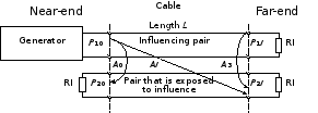
Figure 2.1– Determination of near-end crosstalk attenuation А0, at the far-end of Аl and immunity at the far-end of Ai
The value of crosstalk attenuation at the near-end of the А0 in dB is 10 logarithm of the module power ratio signal Р10 at the near-end of an influencing pair to a noise power Р20 at the near end pair, that exposed to influence:
А0 = 10lg│Р10 /Р20│.
The value of crosstalk attenuation at the far end Аl (in dB) is 10 logarithm of the module power ratio signal Р10 at the near-end of an influencing pair to a noise power Р2l at the far-end pair that exposed to influence:
Аl = 10lg│Р10 /Р2l│.
The value of the immunity at the far-end Аi (in dB) is 10 logarithm of the module power ratio signal Р1l at the far-end of an influencing pair to a noise power Р2l at the far-end pair that exposed to influence:
Аз = 10lg│Р1l /Р2l│.
The crosstalk attenuation at the far-end and the immunity at the far-end are related by own attenuation of a pair equal to the product of the attenuation coefficient α on the cable length l:
Аl = Аз + αl.