
Chemical Tankers / Day 2 / Day 2 topic 4 Vapour Recovery Systems
.pdf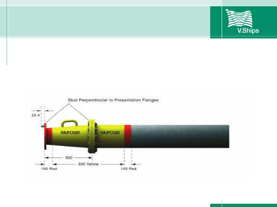
Vapour recovery system design
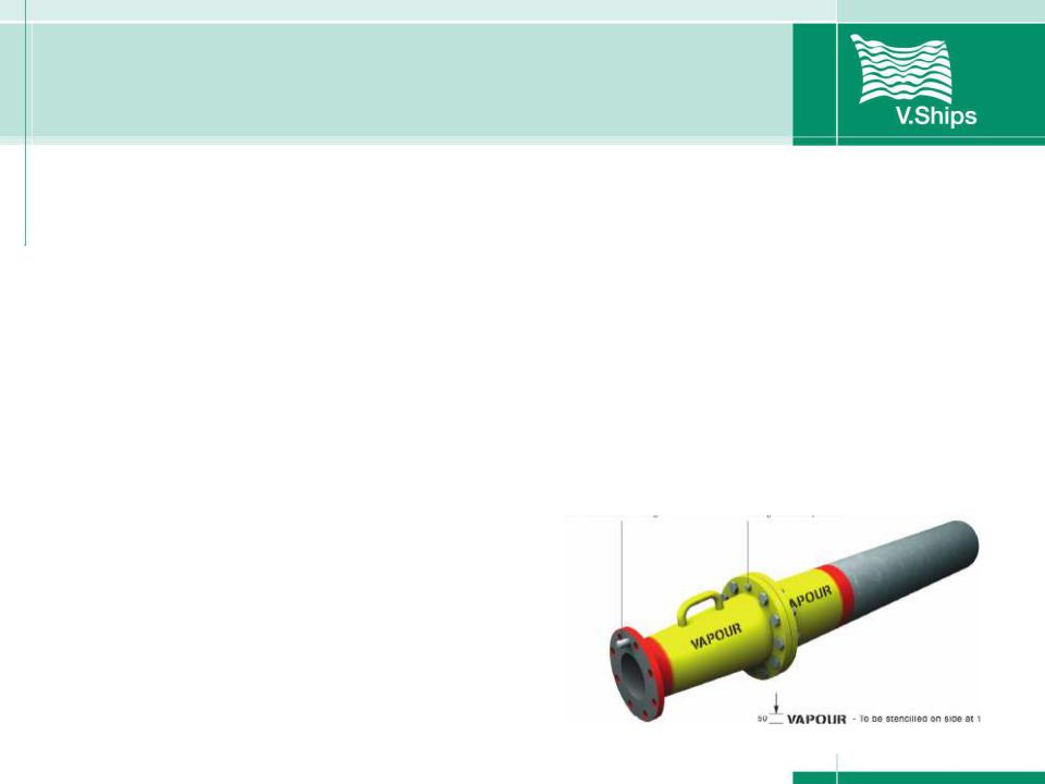
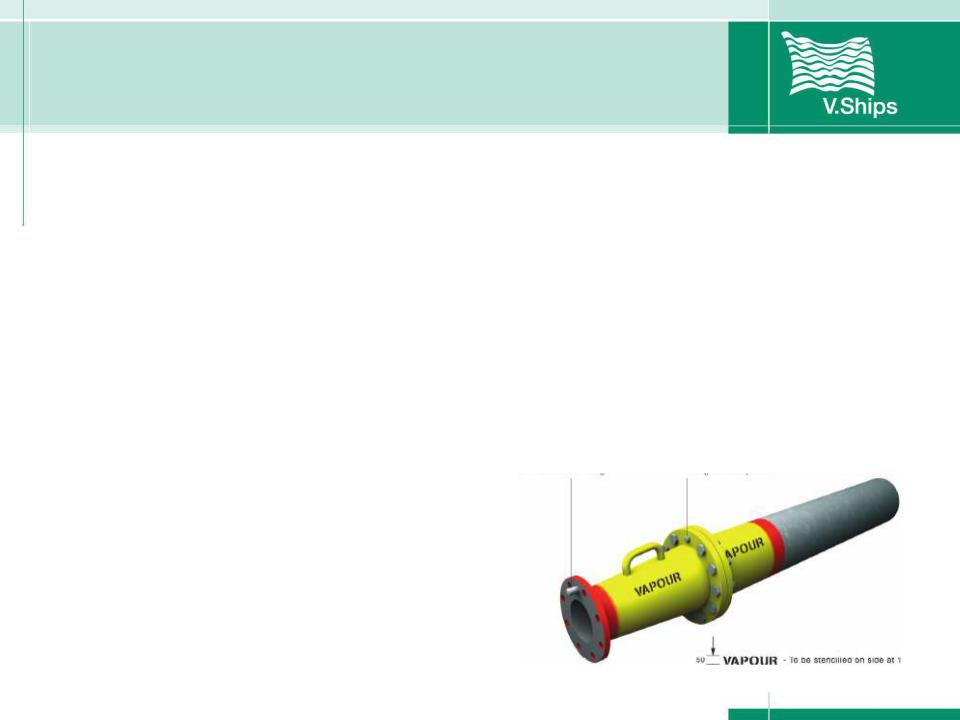
Figure 1 shows the requirements for vapour return line manifolds. These are the minimum standards required and must be marked and identified as shown.
Figure 1
Vapour recovery system design
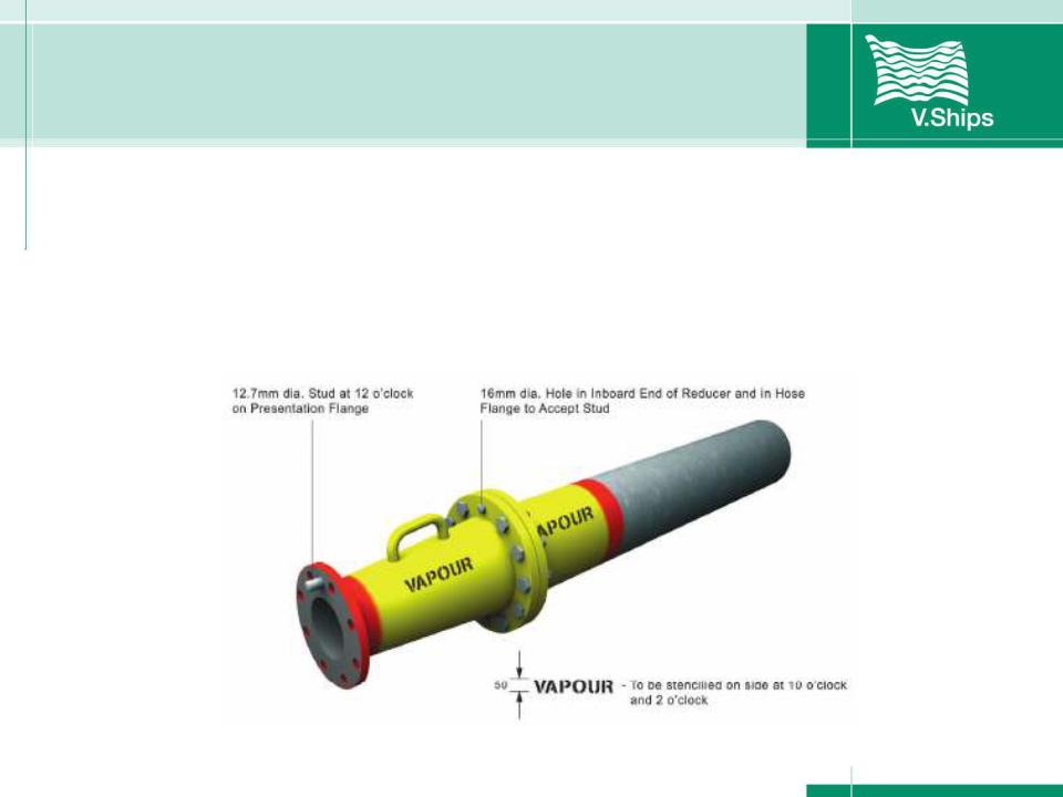
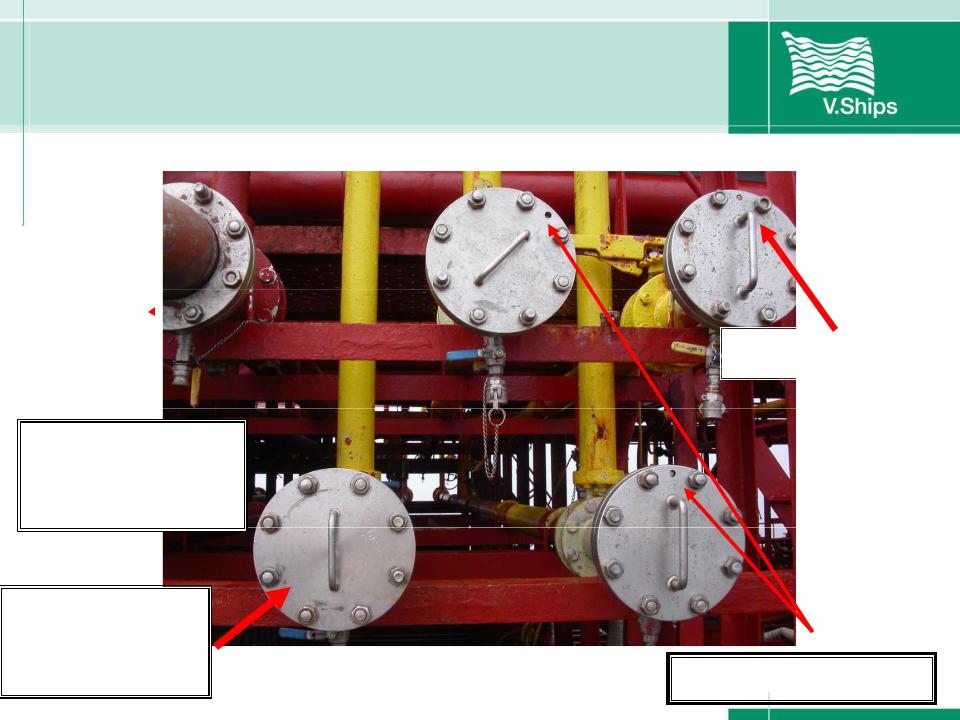
The important item that ensures a cargo line cannot be connected is the "stud" that is set at `12 o'clock' on the flange of the manifold and reducer. This must never be removed and must be replaced if damaged.
Vapour recovery system design
When a shore vapour return arm or hose is presented to the ship for connection, it will have a hole drilled through it at the `12 o'clock' position, of a diameter to accommodate the stud.
The IBC Code lays down the requirements needed for a ship to
meet the demands of returning the most toxic chemical vapours to
shore.
Vapour recovery system design
It is important that there is a balanced safe pressure between the
ship and shore.
The tank must be able to evacuate the vapours at a speed fast enough to
ensure positive pressure is maintained but low enough to ensure that
it is below the set opening pressure of any pressure relief valve in the
tank venting system.

Vapour recovery system design
In new ships today, vapour systems are incorporated at the design stage and purpose built
In older ships, existing pipe work (eg: rail lines) have sometimes been modified as part of the system
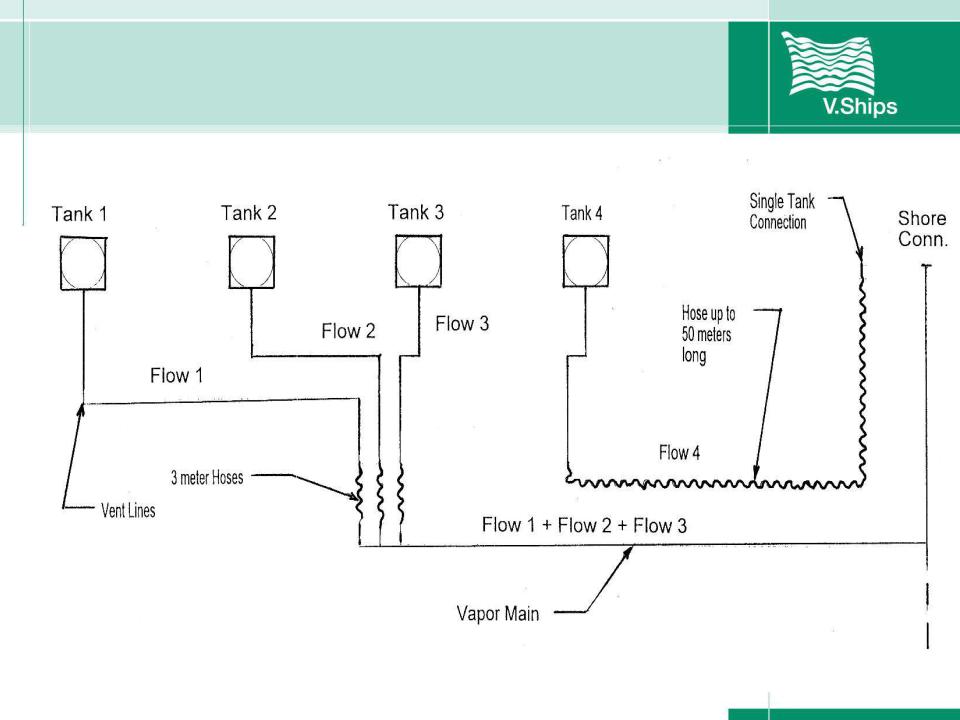
Systems rely on vent piping and a fixed vapor main
Some ships have single tank connection points on either side of the manifolds
Vapour recovery system design
Vapour recovery system design
Hoses:
Short (3m long) hoses may be used to connect the vent lines to the vapor main.
Short (3m long) hoses may be used for interconnection.
Long (up to 50m long) hoses may be used to connect a single tank to the single tank connection point. Two such systems may be used at one time.
Vapour recovery system design
Pin correctly fitted
Incorrect Hose
Flange & Short
Bolts
Cargo Manifold |
|
Flange, no hole |
|
For Pin |
Missing Security Pin |

Vapour recovery system equipment and calculations
Maximum Allowable Transfer Rate depends on:
Capacity of tank vent system – loading rate for a particular tank may not exceed 80% of the vent system capacity
Time to respond to an Overfill Alarm – loading rate for a particular tank must allow 1 minute between the time the overfill (98% or highhigh alarm) sounds and the time the cargo totally fills the tank.
Loading rate for a particular tank must not produce a back pressure in the tank greater than 80% of the P/V valve set pressure
Vapour recovery system equipment and calculations
To ensure that this is met it is very important that, at the pre-cargo operations meeting with the shore terminal staff, there is agreement on the liquid loading rate and the expected pressure at the vapour connection. Plans for how this will be controlled must be in place.
