

© Siemens AG 2012
SINAMICS DCM Cabinet
Ordering and technology
■Schematics
Block diagrams
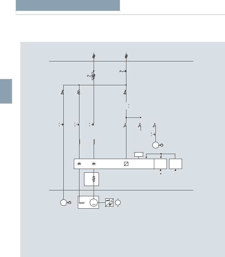
Representative for the converter cabinets, three single-line circuit diagrams will be subsequently shown with the principal electrical design of the basic version. Another diagram shows a
cabinet version with the options that are relevant from an electrical perspective.
Armature supply |
|
Auxiliary supply |
||
|
|
|
|
UN = 400 V/50 Hz |
+Ext.
3
400 V/230 V
|
|
|
|
|
|
|
|
|
|
|
|
|
|
Controls |
|
|
|
Cabinet fan |
|||
|
|
|
|
|
|
|
|
|
|
|
|
|
|
|
|
|
|
|
|
|
|
|
|
|
|
|
|
|
|
|
|
|
|
|
|
|
|
|
|
|
|
|
|
|
|
|
|
|
|
|
|
|
|
|
|
|
|
|
|
|
|
|
|
|
|
|
|
|
|
|
|
|
|
|
|
|
|
|
|
|
|
|
|
|
|
|
|
|
|
|
|
|
|
|
|
|
|
|
|
|
|
|
|
|
|
|
|
|
|
M
1~
|
1) |
+Ext. |
|
M |
M |
3~ |
|
1) Only applicable for 4 quadrant drives
AOP30
DeviceControl-
options options
|
|
|
|
|
|
|
|
|
|
|
|
|
|
G D023 EN 00082 |
|
|
|
|
|
|
|
|
|
|
|
|
|
|
|
|
|
|
|
|
|
|
|
|
|
|
|
|
|
|
|
|
13................. |
|
|
|
|
|
|
|
15 A |
||||
|
|
18................ |
|
|
|
|
|
|
|
30 A |
||||
|
|
................25 |
|
|
|
|
|
|
|
60 A |
||||
|
|
28................ |
|
|
|
|
|
|
|
90 A |
||||
|
|
...............31 |
|
|
|
|
|
|
|
125 A |
||||
|
|
75.............. |
|
|
|
|
|
|
|
210 A |
||||
|
|
78.............. |
|
|
|
|
|
|
|
280 A |
||||
|
|
|
|
|
|
.......D |
400 V |
|||||||
|
|
|
|
|
|
F ....... |
480 V |
|||||||
|
|
|
|
|
|
G....... |
575 V |
|||||||
|
|
|
|
|
|
|
|
|
S2 |
...2 Quadrant |
||||
|
|
|
|
|
|
|
|
|
V6... |
4 Quadrant |
||||
|
|
|
|
|
|
|
|
|
|
|
|
|
|
|
6RM80__-6___2-0AA0
Single-line circuit diagram, rated DC current ≤ 280 A
3/38 |
|
Siemens D 23.2 · 2012 |
|
|
|

© Siemens AG 2012
SINAMICS DCM Cabinet
Ordering and technology
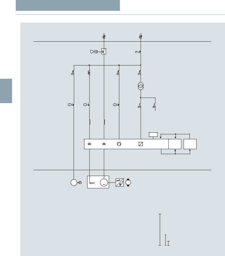
■ Schematics (continued)
Armature supply |
|
Auxiliary supply |
||
|
|
|
|
UN = 400 V/50 Hz |
+Ext.
400 V/230 V |
3 |
|
Controls |
|
1) |
+Ext. |
|
M |
M |
3~ |
|
1) Only applicable for 4 quadrant drives
Single-line circuit diagram, rated DC current ≤ 850 A
AOP30
|
|
|
|
Device- |
|
|
Control- |
|
|||||||
|
|
|
|
options |
|
|
options |
|
|||||||
|
|
|
|
|
|
|
|
|
|
|
|
|
|
|
G D023 EN 00084 |
|
|
|
|
|
|
|
|
|
|
|
|
|
|
|
|
|
|
|
|
|
|
|
|
|
|
|
|
|
|
|
|
|
|
81.............. |
|
|
|
|
|
|
400 A |
||||||
|
|
82.............. |
|
|
|
|
|
|
450 A |
||||||
|
|
..............85 |
|
|
|
|
|
|
600 A |
||||||
|
|
86.............. |
|
|
|
|
|
|
720 A (2Q) |
||||||
|
|
..............86 |
|
|
|
|
|
|
760 A (4Q) |
||||||
|
|
87.............. |
|
|
|
|
|
|
800 A (2Q, 575 V) |
||||||
|
|
87.............. |
|
|
|
|
|
|
850 A |
||||||
|
|
|
|
.......D |
400 V |
||||||||||
|
|
|
|
F ....... |
480 V |
||||||||||
|
|
|
|
G....... |
575 V |
||||||||||
|
|
|
|
K....... |
690 V |
||||||||||
|
|
|
|
|
|
|
...S2 |
2 Quadrant |
|||||||
|
|
|
|
|
|
|
V6... |
4 Quadrant |
|||||||
|
|
|
|
|
|
|
|
|
|
|
|
|
|
|
|
6RM80__-6___2-0AA0
Siemens D 23.2 · 2012 |
|
3/39 |
|
|
|
© Siemens AG 2012
SINAMICS DCM Cabinet
Ordering and technology
■ Schematics (continued)
Armature supply |
|
Auxiliary supply |
||
|
|
|
|
UN = 400 V/50 Hz |
+Ext.
M
3 |
400 V/230 V |
Controls
AOP30
|
|
Device- |
|
Control- |
|
|
|
options |
|
options |
|
|
|
|
|
|
G_D023_EN_00084 |
+Ext. |
|
88 |
950 A |
|
|
|
|
|
|||
|
|
90............... |
1000 |
A |
(690 V) |
M |
M |
90............... |
1100 A (575 V) |
||
3~ |
|
91............... |
1200 A |
|
|
|
|
93............... |
1500 |
A (690 V, 830 V) |
|
|
|
93............... |
1600 |
A |
(400 V, 575 V) |
|
|
95............... |
1900 |
A |
(830 V) |
|
|
95.............. |
2000 |
A |
(400 V, 575 V, 690 V) |
|
|
96.............. |
2200 A |
|
|
|
|
97.............. |
2600 |
A |
(690 V) |
|
|
97.............. |
2800 |
A (575 V) |
|
|
|
98.............. |
3000 A |
|
|
|
|
D.......... |
400 V |
|
|
|
|
F .......... |
480 V |
|
|
|
|
G.......... |
575 V |
|
|
|
|
K.......... |
690 V |
|
|
|
|
L .......... |
830 V |
|
|
|
|
M.......... |
950 V |
|
|
|
|
S2...... |
2 Quadrant |
||
|
|
V6...... |
4 Quadrant |
||
6RM80__-6___2-0AA0 6RM80__-4___2-0AA0
Single-line circuit diagram, rated DC current ≤ 3 000 A
3/40 |
|
Siemens D 23.2 · 2012 |
|
|
|
© Siemens AG 2012
SINAMICS DCM Cabinet
Ordering and technology
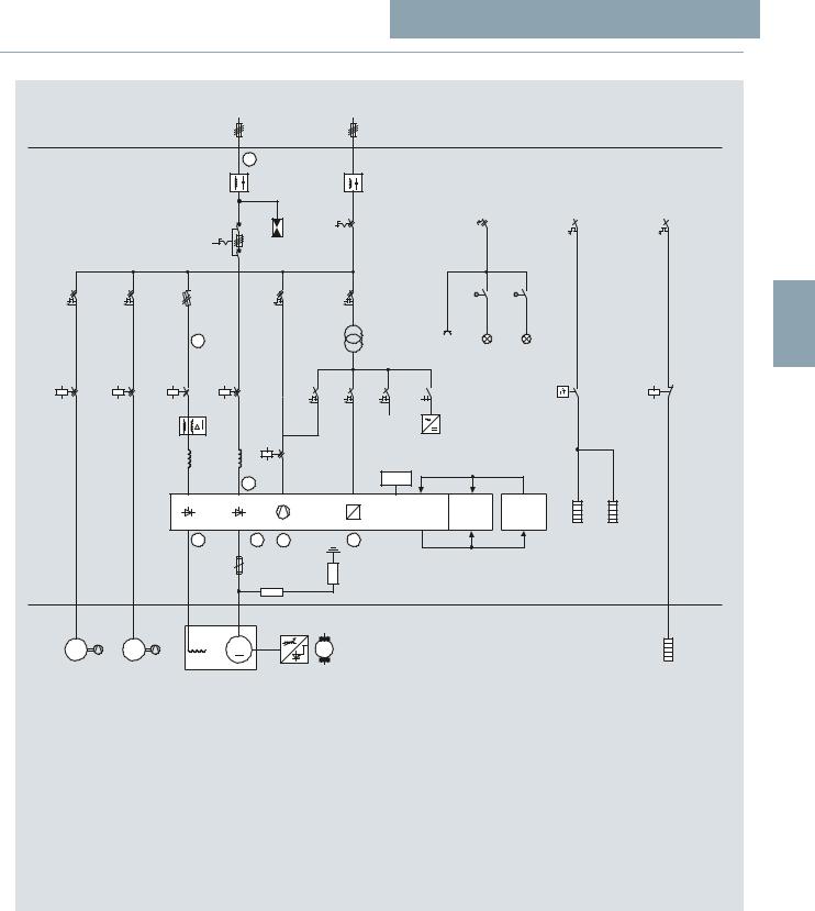
■ Schematics (continued)
Armature supply |
Auxiliary supply |
+Ext. |
|
V +B65 |
|
+L00 |
+L00 |
|
+B83 |
V +B63 |
|
400 V/230 V |
+L82 |
Standard |
+L21 |
|
A +B66 |
AOP30 |
|
|
Auxiliary supply |
Auxiliary supply |
Auxiliary supply |
|||||
UN = 230 V/50 Hz |
UN = 230 V/50 Hz |
UN = 230 V/50 Hz |
|||||
INmax = 13 A |
INmax = 16 A |
INmax = 16 A |
|||||
+L50 |
|
+L55 |
|
+A30 |
|
||
|
|
|
|
|
|
|
|
|
|
|
|
|
|
|
|
3
+L06
+L07
 +L08
+L08
 +L09
+L09
DeviceControl-
options options
|
A +B64 |
A V |
|
n |
|
|
+B62 +B61 |
|
+B60 |
|
|
+L87 |
E |
+L87 |
|
|
+L88 |
|
+L88 |
+Ext. |
|
|
|
|
M |
M |
M |
|
|
3~ |
3~ |
|
|
|
+W70...+W91 |
+W20...+W41 |
+D21 +D22 |
|
|
G_D023_EN_00085
Single-line circuit diagram showing the options that are relevant from an electrical perspective
Siemens D 23.2 · 2012 |
|
3/41 |
|
|
|