

© Siemens AG 2008
Catalog DA 12 • 2008
dc motors
DC motors
Sizes 160 to 630 31.5 kW to 1610 kW

© Siemens AG 2008
Catalogs for "Large Drives"
SINAMICS G130/G150 |
D 11 |
|
|
|
|
|
|||
Drive Converter Chassis Units |
|
|
|
|
Drive Converter Cabinet Units |
|
|
|
|
Order No.: |
|
|
|
|
German: |
E86060-K5511-A101-A3 |
|
|
|
English: |
E86060-K5511-A101-A3-7600 |
|
|
|
|
|
|
|
|
SINAMICS GM150/SM150 |
D 12 |
|
|
|
|
|
|||
Medium-Voltage Converters |
|
|
|
|
0.8 MVA to 28 MVA |
|
|
|
|
Order No.: |
|
|
|
|
German: |
E86060-K5512-A101-A1 |
|
|
|
English: |
E86060-K5512-A101-A1-7600 |
|
|
|
|
|
|
|
|
SINAMICS S120 |
D 21.1 |
|
|
|
|
|
|||
Drive System |
|
|
|
|
0.12 kW to 1200 kW |
|
|
|
|
Order No.: |
|
|
|
|
German: |
E86060-K5521-A111-A2 |
|
|
|
English: |
E86060-K5521-A111-A2-7600 |
|
|
|
|
|
|
|
|
SINAMICS S150 |
D 21.3 |
|
|
|
|
|
|||
Drive Converter Cabinet Units |
|
|
|
|
75 kW to 1200 kW |
|
|
|
|
Order No.: |
|
|
|
|
German: |
E86060-K5521-A131-A1 |
|
|
|
English: |
E86060-K5521-A131-A1-7600 |
|
|
|
|
|
|
|
|
Asynchronous Motors |
D 86.1 |
|
|
|
|
|
|||
Standardline |
|
|
|
|
N-compact 1LA8/H-compact 1LA4 |
|
|
|
|
Order No.: |
|
|
|
|
German: |
E86060-K5586-A111-A2 |
|
|
|
English: |
E86060-K5586-A111-A2-7600 |
|
|
|
|
|
|
|
|
Three-phase synchronous |
D 86.2 |
|
|
|
|
|
|||
motors |
|
|
|
|
HT-direct 1FW4 |
|
|
|
|
Order No.: |
|
|
|
|
German: |
E86060-K5586-A121-A2 |
|
|
|
English: |
E86060-K5586-A121-A2-7600 |
|
|
|
|
|
|
|
|
DC Motors |
DA 12 |
|
|
|
|
|
|||
Sizes 160 to 630 |
|
|
|
|
31.5 kW to 1610 kW |
|
|
|
|
Order No.: |
|
|
|
|
German: |
E86060-K5312-A101-A2 |
|
|
|
English: |
E86060-K5312-A101-A2-7600 |
|
|
|
|
|
|
|
|
DC Motors |
DA 12 T |
|
|
|
|
|
|||
Engineering information |
|
|
|
|
for Catalog DA 12 |
|
|
|
|
Order No.: |
|
|
|
|
German: |
E86060-T5312-A101-A2 |
|
|
|
English: |
E86060-T5312-A101-A2-7600 |
|
|
|
|
|
|
|
|
SIMOREG DC-MASTER 6RA70 |
DA 21.1 |
|
|
|
|
|
|||
Digital Chassis Converters |
|
|
|
|
Order No.: |
|
|
|
|
German: |
E86060-K5321-A111-A2 |
|
|
|
English: |
E86060-K5321-A111-A2-7600 |
|
|
|
www.siemens.com/simoreg-catalog |
|
|
|
|
|
|
|
|
|
|
|
|
|
|
Spare Parts for SIMOREG |
DA 21.1 E |
|
|
|
|
|
|||
DC MASTER 6RA70 |
|
|
|
|
www.siemens.de/simoreg-katalog |
|
|
|
|
www.siemens.com/simoreg-catalog |
|
|
|
|
|
|
|
|
|
|
|
|
|
|
SIMOREG K 6RA22 |
DA 21.2 |
|
|
|
|
|
|||
Analog Chassis Converters |
|
|
|
|
Order No.: |
|
|
|
|
German: |
E86060-K5121-A121-A1 |
|
|
|
English: |
E86060-K5121-A121-A1-7600 |
|
|
|
|
|
|
|
|
|
|
|
|
|
SIMOREG DC MASTER 6RM70 |
DA 22 |
|
|
|
|
|
|||
Digital Converter Cabinet Units |
|
|
|
|
www.siemens.de/simoreg-katalog |
|
|
|
|
www.siemens.com/simoreg-catalog |
|
|
|
|
|
|
|
|
|
|
|
|
|
|
Catalog CA 01 |
CA 01 |
|
|
|
The Offline Mall of Automation |
|
|
|
|
and Drives |
|
|
|
|
Order No.: |
|
|
|
|
German: |
E86060-D4001-A100-C6 (CD-ROM) |
|
|
|
|
E86060-D4001-A500-C6 (DVD) |
|
|
|
English: |
E86060-D4001-A110-C6-7600 (CD-ROM) |
|
|
|
|
E86060-D4001-A510-C6-7600 (DVD) |
|
|
|
|
|
|
|
|
A&D Mall
Internet: www.siemens.com/automation/mall
SINAMICS MICROMASTER SIZER
Configuration tool
Order No.: 6SL3070-0AA00-0AG0
The configuration of DC-motors and converters is realized via SIZER LD Snap-in Suite, which has to be obtained from the regional contact partner and installed in addition to the SINAMICS MICROMASTER SIZER.
© Siemens AG 2008 |
|
|
DC motors |
Introduction |
and Drives |
Sizes 160 to 630 |
Welcome to Automation |
|
|
of prime importance |
|
|
|
DC technology remains |
31.5 kW to 1610 kW |
|
DC motors – For what |
|
types of applications? |
|
Catalog DA 12 · 2008 |
|
Why use DC motors from |
|
Siemens? |
Supersedes:
Catalog DA 12 · 2004
© Siemens AG 2007
The products and systems described in this catalog are manufactured under application of a quality management system certified by DQS in accordance with EN ISO 9001 (Certificate Registration No. 002241 QM UM).
The certificate is recognized in all IQ Net countries.
Explanations
Selection and ordering Guideline Order No. code
Order No. supplements
Selection and ordering data
Options
Dimensions
Appendix |
Regulations, standards |
|
and specifications |
|
Siemens contact part- |
|
ners worldwide |
|
A&D online services |
|
Customer support |
|
Indices |
|
Conditions of sale and |
|
delivery |
s
1
2
3
4
5
© Siemens AG 2008
Welcome to
Automation and Drives
We would like to welcome you to Automation and Drives and our comprehensive range of products, systems, solutions and services for production and process automation and building technology worldwide.
With Totally Integrated Automation and Totally Integrated Power, we deliver solution platforms based on standards that offer you a considerable savings potential.
Discover the world of our technology now. If you need more detailed information, please contact one of your regional Siemens partners. They will be glad to assist you.
|
|
|
|
|
|
|
|
|
1/2 |
Siemens DA 12 · 2008 |
|
|
|
|
|
© Siemens AG 2008
True values endure – DC technology
remains of prime importance
– even if its immediate demise has been forecast for more than fifteen years: Siemens Automation & Drives will continue to provide this simple and user-friendly technology into the future. After all, it has proved itself to be reliable in daily use for decades and therefore remains of prime importance.
With our extensive know-how and with more than 125 years of experience, we remain your reliable partner for all your DC drive requirements. We offer perfect up-to- date solutions for both new plants or retrofitting. We are constantly working on the further development of the DC technology.
The perfect examples: SIMOREG® DC Master, Control Module and Converter Commutation Protector, the perfect solutions for your DC drives – and the most effective method to safeguard your investments permanently.
http://www.siemens.com/simoreg
Siemens DA 12 · 2008 |
1/3 |
|
|
© Siemens AG 2008
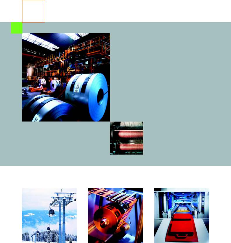
DC motors – For what types of application?
The modular DC motors are well-proven in combination with static converters as variable-speed drives in almost all industry sectors.
This secures competitive strength and efficiency – internationally as well.
Our DC drives are the optimum solution, no matter which functions have to be fulfilled in drive, power or process engineering.
For example:
•In elevators and cable cars
•In rolling mills
•For hoisting equiment
•In the textile and man-made fiber industries
•In the printing industry
•In the basic industries
1/4 |
Siemens DA 12 · 2008 |
|
|
© Siemens AG 2008
Why use DC motors from Siemens?
Siemens DC drives distinguish themselves as follows:
•Their excellent static and dynamic control response
•Their wide range with high control precision
•The high efficiency of the complete drive system.
DC motors continue to be a high-quality alternative to three-phase motors. Together with SIMOREG drive converters, they form optimum, variablespeed drives for numerous branches of industry and are used wherever there is a requirement for favorably priced technology and high availability.
Outstanding features:
•High power density with small motor dimensions
•High thermal reserves for continuous duty and overload thanks to the DURIGNIT 2000® insulating system
•Minimal losses thanks to excellent efficiency
•High quality of smooth running and vibration
•Low noise values
•High mechanical rigidity
•Low weight
•Long brush lifetimes thanks to optimized commutation system
•High operational reliability and availability thanks to numerous diagnostic functions when fed from SIMOREG drive converters.
|
|
|
|
|
|
Siemens DA 12 · 2008 |
1/5 |
|
|
|
|
© Siemens AG 2008
1/6 |
Siemens DA 12 · 2008 |
|
|
© Siemens AG 2008
Explanations
|
2/2 |
Motor design |
|
|
2/2 |
Magnetic circuit, rate of change of |
|
|
|
|
current |
|
2/2 |
Rotors |
|
|
2/2 |
Carbon brushes, commutation |
|
|
2/2 |
Supply, converter connection and |
|
|
|
|
armature voltage |
|
2/2 |
Installation and operating |
|
|
|
|
conditions |
|
2/3 |
Intermittent duty |
|
|
2/3 |
DURIGNIT 2000 insulating system |
|
|
2/3 |
Rated power |
|
|
2/3 |
Direction of rotation |
|
|
2/3 |
Field control range |
|
|
2/3 |
Speed data on the rating plate |
|
|
2/3 |
Sector-specific applications |
|
|
2/3 |
Paint finish |
|
|
2/3 |
Aggressive gases and vapors |
|
|
2/4 |
Noise levels |
|
|
2/4 |
Bearings |
|
|
|
2/4 |
Cooling and ventilation |
|
|
||
|
|
2/5 |
Encoders |
|
|
2/5 |
Protection and monitoring |
|
|
2/6 |
Terminal boxes |
|
|
2/6 |
Shaft ends |
|
|
2/6 |
Balancing |
|
|
|
|
|
|
|
|
Siemens DA 12 · 2008
© Siemens AG 2008
Explanations
Motor design
The DC motors up to and including Size 280 are uncompensated. From Size 355, the motors are equipped with a compensation winding.
At constant torque, the forced-cooled motors 1GH, 1GG, 1HQ and 1HS can be coasted down to 10 rpm by means of armature control.
Magnetic circuit, rate of change of current
The motors have a fully laminated magnetic circuit and are there-
2fore suitable for being fed from converter units. In the case of dynamic processes, a rate of change of current up to 250 IN/s is permissible.
Rotors
The laminated rotor packages have chamfered slots to minimize noise and torque ripple. The rotors are dynamically balanced.
Carbon brushes, commutation
Practically spark-free commutation when fed from drive converters is achieved as a result of the optimum motor design, even in the overload range. This results in extremely long brush lifetimes.
Brush wear is essentially dependent on the operating and ambient conditions of the DC motor, so the following conditions should apply in order to achieve a long brush lifetime:
Operating conditions
The motors are designed for the following conditions of operation:
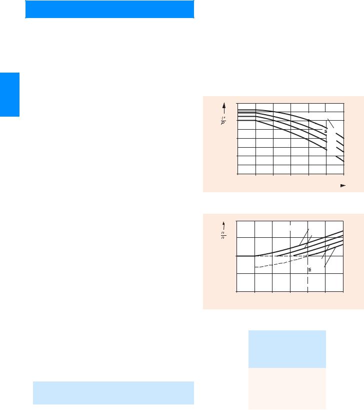
•Site altitude ≤ 1000 m (> 1000 m, see adjacent characteristics)
•Cooling air temperature up to 40 °C (> 40 °C, see adjacent characteristics)
•Cooling air must not contain any foreign bodies or aggressive components
•Maximum permissible vibration levels from external sources (see adjacent table).
120 |
|
00018 |
% |
|
|
N |
Site altitude |
EN |
|
DA12G |
|
100 |
|
|
|
1000 m |
|
80 |
2000 m |
|
|
3000 m |
|
60 |
4000 m |
|
|
|
|
40 |
|
|
0 |
10 |
20 |
30 |
40 |
50 °C 60 |
||
|
|
|
Coolant supply temperature |
|
|
||
|
|
|
|
||||
•Relative air humidity 10 to 50%
•Effective load > 50% IN
•Cooling air temperature > 10 °C
For conditions outside these ranges, information is available on request.
Critical applications can also be mastered if the appropriate brush materials are chosen.
Supply, converter connection and armature voltage
The rated voltages listed in the selection tables are rated voltages according to DIN 40 030.
The rated data assigned to each of these rated voltages is only valid in combination with the specified converter connection and supply voltage. The inductances specified in the "Selection and ordering data" tables are applicable for 300 Hz with three-phase bridge circuits and a line frequency of 50 Hz, which is generally specified on the rating plate.
Output changes as a function of the site altitude and the coolant supply temperature for DC motors.
120 |
|
|
|
|
|
|
00019 |
|
|
|
Site altitude 4000 m |
|
|||
% |
|
|
|
|
3000 m |
|
EN |
|
|
|
|
|
|
G DA12 |
|
n |
|
|
|
|
|
|
|
|
|
|
|
|
|
|
|
100 |
|
|
|
|
|
|
|
|
|
|
|
|
2000 m |
|
|
|
|
|
|
|
1000 m |
|
|
80 |
|
|
30 |
40 |
50 |
°C |
60 |
0 |
10 |
20 |
|||||
Coolant supply temperature 
Installation and operating conditions
Condensation
If there is a risk of condensation, anti-condensation heating can be fitted to the motors. Supply voltages of 115 V and 230 V are permitted.
Overload capability
Overloading of the motors is possible in accordance with the following table. In the event of frequent overloading, it is assumed that the effective load of the motor does not exceed the rated load.
Overload capacity (with reference to PN and nN) for
|
motors without |
motors with |
|
|
|
compensation |
compensation |
||
|
|
|
|
|
|
Torque |
Current |
Torque |
Current |
|
Mmax/MN |
Imax/IN |
Mmax/MN |
Imax/IN |
15 s |
1.6 |
~ 1.85 |
1.8 |
~ 1.85 |
5 s |
1.8 |
~ 2.2 |
2.0 |
~ 2.1 |
|
|
|
|
|
Speed deviations as a function of the site altitude and the coolant supply temperature for DC motors.
Vibration |
|
Vibration |
|
|
frequency |
|
values |
|
|
Hz |
|
Frame size |
||
|
|
Up to |
355 |
|
|
|
280 |
and |
|
|
|
|
above |
|
< 6.3 |
Vibration displacement s |
≤ 0.1 |
≤ |
0.16 |
|
mm |
|
|
|
6.3 – 63 |
Vibration velocity Vrms |
≤ 2.8 |
≤ |
4.5 |
|
mm/s |
|
|
|
> 63 |
Vibration acceleration a |
≤ 1.6 |
≤ |
2.55 |
|
m/s2 |
|
|
|
The valuation zones A and B defined in ISO 10816 apply for the permissible vibration values measured on the end shield. With increased vibration values due to operation, special agreements have to be made (on request).
2/2 |
Siemens DA 12 · 2008 |
|
|
© Siemens AG 2008
Explanations
Intermittent duty
The following increases in output can be assumed with reference to the rated outputs listed in the "Selection and ordering data" for separately ventilated motors in S3 mode (intermittent duty):
S3 operating mode |
Increase in output from PN in S1 |
|
operating mode |
–60% |
1.15 |
–40% |
1.3 |
–25% |
1.5 |
|
|
DURIGNIT 2000 insulating system
The high-quality DURIGINIT 2000 insulating system mainly comprises plastic materials with a high temperature overload capability and track resistance. It also meets the requirements placed on motors that are operating in tropical conditions (humid and hot climate).
Temperature class 155 (F) (overtemperature limit 105 K at
KT 40 °C) is implemented for 1G.5/1H.5 motors. For utilization in temperature class 130 (B), derating of 13% to 87% must be implemented.
Temperature class 180 (H) (overtemperature limit 125 K at
KT 40 °C) is implemented for 1G.6/1H.6 and 1G.7/1H.7 motors. For utilization in temperature class 155 (F), derating of 8% to 92% is necessary (103% speed).
Rated output
The rated output specified in the selection tables is applicable for S1 continuous duty according to EN 60 034-1 when the motors are fed from drive converters using the applicable converter connections and supply voltages specified for the rated armature voltages.
Direction of rotation
The motors are designed for both clockwise and anti-clockwise rotation or reversing operation. The direction of rotation only has to be specified for motors of Size 500 and 630.
Field control range
The motor speed can be increased by field weakening
•At constant armature voltage and power as far as the field
weakening speeds nFmax specified in the "Selection and ordering data" tables
•Beyond these values, as far as the maximum permissible me-
chanical limit speed nmech as specified in the "Selection and ordering data" tables with reduced power Pred as follows:
|
|
n * |
|
|
1 |
|
Pred |
|
nF |
|
|
PN |
|
|
|
|
|
|||
|
n * |
|
|
|
nFmax1
n* Fictitious reference value with units of speed from the table shown below
nF Required field weakening speed in the range nFmax < nF ≤ nmech
Speeds n* (fictitious reference values only)
Motor Size |
Speed n* |
|
|
|
rpm |
|
|
|
|
|
|
160 |
14400 |
|
|
180 |
13000 |
|
|
200 |
11700 |
|
|
|
|
|
|
225 |
10500 |
|
|
250 |
9400 |
|
2 |
280 |
8300 |
|
|
|
|
||
355 |
6400 |
|
|
400 |
5700 |
|
|
450 |
4950 |
|
|
500 |
4580 |
|
|
630 |
3580 |
|
|
|
|
|
|
In the speed range from nFmax to nmech, the series inductances and noise values can increase; further details on request.
Speed data on the rating plate
If specified in the order, the field weakening speed will be given on the rating plate as shown in the following table.
Design |
|
Field weakening speed nF |
|
|
|
rpm |
|
Standard design |
|
1.15 nN maximum nFmax |
|
|
|
(see selection tables) |
|
Special design in accordance |
C05 |
1.7 nN maximum nFmax |
|
with the section of the catalog |
|
(see selection tables) |
|
"Selection and ordering" - |
|
|
|
C06 |
nFmax > 1.7 nN |
||
"Options" for an additional |
price, with short code
If the speeds of the respective motor deviate from those specified in the "Selection and ordering data" tables, for example, due to
•Speed compensation by means of armature voltage changes and/or field weakening
•Additional, permissible field weakening speeds not specified for the standard design (without a short code or for short codes
C05 and C06)
the short code Y80 "Deviating rating plate data" and information in plain text must also be specified, see "Selection and ordering" - "Options".
Sector-specific applications
Short codes are specified for the following sector-specific applications (see "Selection and ordering" - "Options").
Paint finish
The standard paint color is anthracite according to RAL 7016. Motors can be supplied with a special paint finish (short code L53) or with primer only (short code K24).
Aggressive gases and vapors
If chemically aggressive gases and vapors are expected at the installation site, additional precautions must be taken with regard to insulation, surface protection and brush types. Please inquire specifying the substance type and concentration.
Siemens DA 12 · 2008 |
2/3 |
|
|

© Siemens AG 2008
Explanations
Noise levels
The noise levels of the motors have been determined according to ISO 1680/ISO 3744 and lie far below the values permitted according to EN 60 034-9. This has been achieved thanks to the mechanical design and by optimizing the magnetic circuit and the ventilation.
The sound pressure level LpA and the acoustic power level LWA (acc. to the table below, including tolerance) are applicable at full load up to 2000 rpm, for converter infeed in B6C connection and with a standard external fan at 50 Hz.
2The acoustic power level LWA is the sum of measuring surface size and the measuring surface sound pressure level LpA.
For comparisons with the standard, a no-load/load differential of the machine noise of 3 to 5 dB can be assumed. The no-load noise values for an infeed of pure DC current lie about 3 dB below the noise values for converter infeed.
When a filter is installed, the noise values are reduced by 1 to 2 dB.
When a silencer is used (see "Selection and ordering" - "Options"), the noise values are reduced by approx. 5 dB.
Frame size Measuring surface |
Acoustic power level |
|||
|
sound pressure level |
LWA |
|
|
|
LpA |
|
|
|
|
dB (A) |
|
dB (A) |
|
|
1GG6 and 1GH6 motors |
|
|
|
|
|
|
||
160 |
73 |
|
86 |
|
|
1G.6/ and 1H.6 motors |
|
|
|
|
1GH6 |
1GG6 |
1GH6 |
1GG6 |
|
1HS6 |
1HQ6 |
1HS6 |
1HQ6 |
180 |
72 |
76 |
85 |
90 |
200 |
73 |
77 |
87 |
91 |
225 |
76 |
80 |
90 |
94 |
250 |
78 |
82 |
93 |
97 |
280 |
80 |
84 |
95 |
99 |
|
|
|
|
|
Noise values are available for larger motors on request.
Bearings
Motors up to and including Size 200 have roller bearings (grooved ball bearings) with permanent lubrication. Larger motors are provided with a regreasing device. In the case of increased lateral forces, a special version of the drive-end bearing is required (see "Selection and ordering" - "Options" and the project engineering manual).
In all motors, the fixed bearings are at the non-drive end.
For positioning angles up to the vertical, the bearings of the motors up to Size 280 can carry the weight of the rotor as well as one half of the coupling. In the case of additional axial loads, please inquire.
Cooling and ventilation
Cooling:
The cooling air is normally fed from the non-drive end (NDE) to the drive end (DE), i.e. from the commutator end to the output end, where it discharges through vents to the left and right. This direction of air flow is necessary to achieve adequate cooling for the commutator for motors operating at high speeds and outputs.
The direction of air flow can be reversed (from the drive end to the non-drive end; i.e. from the output end to the commutator end). This is recommended for motors operated with weak loads, low cooling-air intake temperature, or under harsh ambient conditions (aggressive gases, organic liquids, dust, etc.) Derating may be necessary under some circumstances (on request).
The fan unit of the 1GG motors can also be retrofitted to 1GH motors.
Frame size Cooling air |
Permissible pressure |
Required |
|
|
flow |
drop in the ducts |
pressure |
|
· |
for 1GG motors |
for 1GH motors |
|
p |
p |
|
|
V |
||
|
m3/s |
Pa |
Pa |
|
|||
1GG6, 1GH6 |
|
|
|
|
|
|
|
160 |
0.20 |
60 |
1300 |
180 |
0.30 |
70 |
1350 |
200 |
0.35 |
70 |
1250 |
225 |
0.50 |
80 |
1600 |
250 |
0.60 |
80 |
1500 |
280 |
0.75 |
80 |
1600 |
|
|
|
|
1GG7, 1GH7 |
|
|
|
|
|
|
|
351 |
1.3 |
100 |
1800 |
352 |
|
|
1900 |
353 |
|
|
2000 |
354 |
|
|
2300 |
355 |
|
|
2500 |
401 |
1.6 |
100 |
1800 |
402 |
|
|
1900 |
403 |
|
|
2100 |
404 |
|
|
2200 |
405 |
|
|
2500 |
451 |
2.0 |
100 |
1700 |
452 |
|
|
1800 |
453 |
|
|
2000 |
454 |
|
|
2200 |
455 |
|
|
2400 |
|
|
|
|
1GG5, 1GH5 |
|
|
|
|
|
|
|
500 |
2.0 |
70 |
1400 |
630 |
3.0 |
70 |
1350 |
|
|
|
|
2/4 |
Siemens DA 12 · 2008 |
|
|