

Справочные данные / da22-en
.pdfSIMOREG DC MASTER 6RM70
Digital Converter Cabinet Units
Catalog DA 22 × 2002
DC DRIVES

Catalogs for “Large Drives”
DC Motors |
DA 12 |
||
Order No.: |
|
|
|
German: |
E20002-K4012-A101-A2 |
|
|
English: E20002-K4012-A101-A2-7600 |
|
|
|
|
|
|
|
DC Motors |
DA 12 Supplement |
||
1GG7, 1GH7, 1HS7 and 1HQ7 |
May 2001 |
||
Order No.: |
|
|
|
German: |
E86060-K5112-E101-A1 |
|
|
English: E86060-K5112-E101-A1-7600 |
|
|
|
|
|
|
|
DC Drives |
|
DA 12.1 |
|
Preferred Series up to 500 kW |
|
|
|
Order No.: |
|
|
|
German: |
E20002-K4012-A111-A2 |
|
|
English: E20002-K4012-A111-A2-7600 |
|
|
|
|
|
|
|
DC Drives |
|
DA 12.2 |
|
Preferred Series 215 kW to 1500 kW |
|
|
|
Order No.: |
|
|
|
German: |
E20002-K4012-A121-A1 |
|
|
English: E20002-K4012-A121-A1-7600 |
|
|
|
|
|
|
|
SIMOREG DC MASTER 6RA70 |
DA 21.1 |
||
Digital Chassis Converters |
|
|
|
Order No.: |
|
|
|
German: |
E86060-K5121-A111-A1 |
|
|
English: E86060-K5121-A111-A1-7600 |
|
|
|
French: |
E86060-K5121-A111-A1-7700 |
|
|
|
|
|
|
SIMOREG K 6RA22 |
DA 21.2 |
||
Analog Chassis Converters |
|
|
|
Order No.: |
|
|
|
German: |
E86060-K4021-A121-A1 |
|
|
English: E86060-K4021-A121-A1-7600 |
|
|
|
|
|
|
|
Spare Parts for SIMOREG |
DA 21 E |
||
Converters (Chassis Units) |
|
|
|
www.siemens.de/simoreg |
|
|
|
www.siemens.com/simoreg |
|
|
|
|
|
|
|
SIMOREG DC MASTER 6RM70 |
DA 22 |
||
Digital Converter Cabinet Units |
|
|
|
Order No.: |
|
|
|
German: |
E86060-K5122-A101-A1 |
|
|
English: E86060-K5122-A101-A1-7600 |
|
|
|
|
|
|
|
Automation |
CA 01 |
|
|
|
|||
and Drives |
|
|
|
Order No.: |
|
|
|
German: |
E86060-D4001-A100-B6 |
|
|
English: |
E86060-D4001-A110-B4-7600 |
|
|
|
|
||
|
|
|
|
Internet
Visit Siemens Automation and Drives Group on the Internet at http://www.siemens.de/automation

s
SIMOREG
DC MASTER 6RM70
Digital Converter
Cabinet Units
Catalog DA 22 ¼ 2002
Supersedes: Catalog DA 22 ¼ 2000
|
Page |
Description |
3 |
Block Diagrams |
6 |
Technical Data |
18 |
Terminal Assignment |
21 |
Selection and Ordering Data |
23 |
Options |
28 |
Dimension Drawings |
37 |
Appendix |
39 |

Please note:
The technical data is intended for general information.
Please observe the Operating Instructions and the references indicated on the products for installation, operation and maintenance.
® SILIZED, SIMADYN, SIMOLINK, SIMOREG, SITOR and USS are Siemens registered trademarks.
All other products and system names in this catalog are (registered) trademarks of their respective owners and must be treated accordingly.
 The technical data, selection and ordering data (Order Nos.), accessories and availability are subject to alteration.
 All dimensions in this catalog are stated in mm.
© Siemens AG 2001
SIMOREG DC MASTER 6RM70
Digital Converter Cabinet Units
Description
■Applications
SIMOREG® converter cabinet units are tested drive converter units, which are ready to con- nect-up to supply variablespeed DC motors. All of the open-loop and closed-loop control functions as well as the monitoringand auxiliary functions are handled by two microprocessors in the SIMOREG. The cabinet units include all of the components which are required to operate a variablespeed DC motor.
The cabinet units can be directly connected to 3-phase line supplies with rated voltages of 3-ph. 400 V AC, 500 V, 690 V, 830 V AC, 50 Hz and 3-ph. 460 V AC, 60 Hz.
Other supply voltages between 3-ph. 90 V AC and 830 V AC as well as 60 Hz or 50 Hz line frequencies, refer to the options.
Cabinet units are available for:
■Single-quadrant/two-quad- rant operation with a fullycontrolled six-pulse bridge circuit B6C (rated DC currents 30 A to 2000 A)
■Four-quadrant operation with an antiparallel circuit with two fully-controlled six-pulse bridge circuits (B6)A(B6)C (rated DC currents 15 A to 2000 A)
■Special versions for parallel connection, 12-pulse operation and field supply on request.
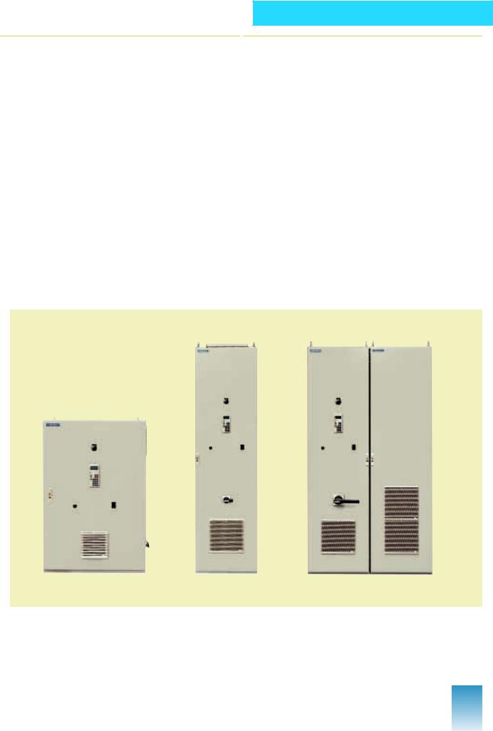
Examples of SIMOREG converter cabinet units
■Design
The cabinet units contain the following components:
■SIMOREG DC MASTER 6RA70 drive converters with microprocessor-based digital closed-loop control for the armatureand field circuits
■Main switch (=D3-Q11)
■Main contactor (=D3-K11)
■Field contactor (=G1-K11)
■Circuit-breaker
■Motor protection circuitbreaker
■Fuses
■Commutating reactors
■Control voltage transformers
■Displayand operator control elements
■Terminals.
The components are mounted in a cabinet, and are ready to be connected-up (cabinet system: Rittal TS8). All of the components are accessible from the front of the cabinet, i.e. the cabinet units can be mounted with their rear panels to walls. For units up to 60 A, the main switch is mounted on the side.
Siemens DA 22 · 2002 |
3 |
SIMOREG DC MASTER 6RM70
Digital Converter Cabinet Units
Description
■Mode of operation and functions
Also refer to the block diagram.
Line supply
Cabinet units can be directly connected to three-phase line supplies (refer to Technical Data for the nominal data). The feeder cables to the drive converter must be protected against short-circuit and overload (DIN VDE 0160/
DIN VDE 0100, Part 540). The cable is entered at the bottom side.
Main switch
For cabinet units from 15 to 1200 A, the three-phase line supply is connected to the unit via the main switch =D3-Q11. Cabinet units larger than 1200 A have an electricallyactuated circuit-breaker =D3-Q11 and a control voltage main switch =D3-S11.
Main contactor/ circuit-breaker
The main contactor =D3-K11 or the circuit-breaker =D3-Q11 can be switched-in or -out using a relay, mounted in the cabinet unit via the field contactor =G1-K11. A microprocessor in the drive converter automatically controls the relay at the correct instant within the power-up or power-down routine.
Miniature circuit-breaker and motor protection cir- cuit-breaker
Miniature circuit-breaker and motor protection circuit-break- er protect the electronics power supply, as well as the auxiliary circuits and the motor fan and the fan against short-circuit and overload.
Fuses
SITOR® or SILIZED® fuse links protect the thyristors and the field rectifier of the cabinet unit.
Commutating reactors
Commutating reactors for the armatureand field circuit limit the commutating dips in the line supply voltage in accordance with DIN VDE 0160. They are designed for operation with 100 % rated current.
Control voltage transformers
A control voltage transformer 400/230 V is used for the electronics power supply and the open-loop control. For drive converter input voltages greater than 3-ph. 400 V AC, an additional auxiliary voltage supply 3-ph. 400 V AC is required on the part of the customer. Control voltage transformers can also be supplied if requested, see page 33.
Displayand operator control elements
The following equipment is mounted in the cabinet doors:
■Mushroom-head pushbutton switch E-Stop, black, latching. No EMERGENCYOFF acc. to EN 60 204-1.
■10-turn setpoint potentiometer
■Mode selector switch, INTERNAL-EXTERNAL
■OP1S operator control panel.
The operator control panel is used to
●Set the cabinet unit parameters
●Display measured values
●The open-loop control is executed in the INTERNAL mode:
–setpoint input via motorized potentiometer
–power-on (I)
–power-down (O)
–jogging
–reversing.
●Display and acknowledge error messages.
“External” operating mode
In this mode, the setpoint is entered and the equipment controlled via the terminals of the unit or via serial interfaces or optional bus connection to automation systems.
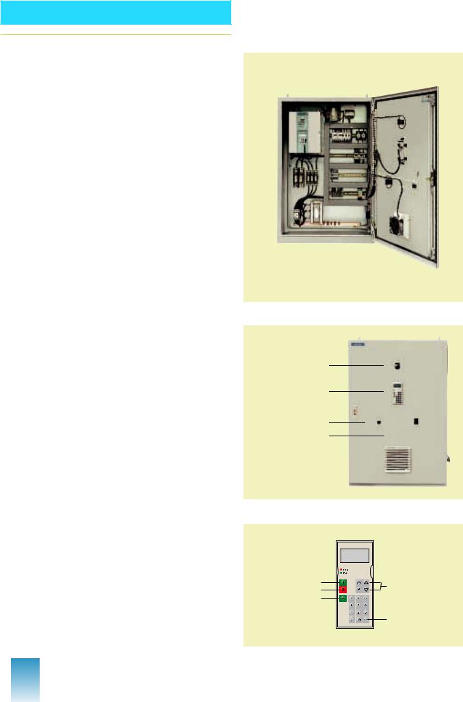
Example
SIMOREG converter cabinet unit, 30 A, open
Displayand operator control elements
Mushroom-head pushbutton switch E-Stop
OP1S
operator control panel
Setpoint potentiometer
Mode selector switch
OP1S operator control panel
Power-on
Power-down
Jogging
DA22-5013a |
Motorized potentiometer
Acknowledge
4 |
Siemens DA 22 · 2002 |
■Mode of operation and functions
Drive converters
The following drive converters are used:
■for single-/two-quadrant operation, the SIMOREG DC MASTER 6RA70..-..S22-0.
■for four-quadrant operation, the SIMOREG DC MASTER 6RA70..-..V62-0.
The equipment options K00 (terminal expansion) and D64 (Operating Instructions, multilingual, as well as the operator control program DriveMonitor on CD-ROM), are included in the scope of supply.
SIMOREG DC MASTER 6RA70 are fully-digital, linecommutated drive converters which are connected to threephase line supplies. They are used to control the armatureand field circuits of variablespeed DC motors. The rated DC current, specified on the equipment rating plate (= maximum permissible continuous DC current) can be exceeded up to 1.8 times in operation. The maximum overload time depends on the overload current characteristics and the preload condition of the drive converter and is drive-convert- er specific. The overload capacity is configured using Catalog DA 21.1.
As a result of an integrated parameterizing device, the drive units are autonomous and no additional programmingor measuring equipment is required to parameterize them. All of the functions of the openloop and closed-loop control for the armatureand field circuits are realized in two highperformance 16-bit microprocessors.
The closed-loop control functions are implemented as program modules in the software, which can be linked using parameters. The drive converters have an additional series of technological functions with the software option (code S00). These include, for example, higher-level technology controllers, freely-assignable adders, multipliers and dividers, logical blocks, timers, limit value monitors, etc.
The T400 technology module can be used for additional technological functions, for example, winders or synchronous controls (codes D30 to D32). The cabinet units have three serial interfaces. One is used to couple the unit to the operator panel OP1S. Two additional interfaces can be freely used, e.g. to establish a unit-unit link via the peer-to-peer protocol, couple to a PC or to an automation system via the USS protocol.
The cabinet units can be connected to PROFIBUS via the CBP2 interface module (code
D36).
Additional information is provided in Catalog DA 21.1.
SIMOREG DC MASTER 6RM70
Digital Converter Cabinet Units
Description
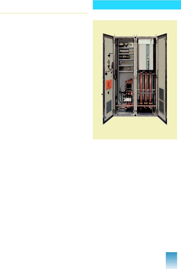
Example
SIMOREG converter cabinet unit, 1200 A, open
Siemens DA 22 · 2002 |
5 |
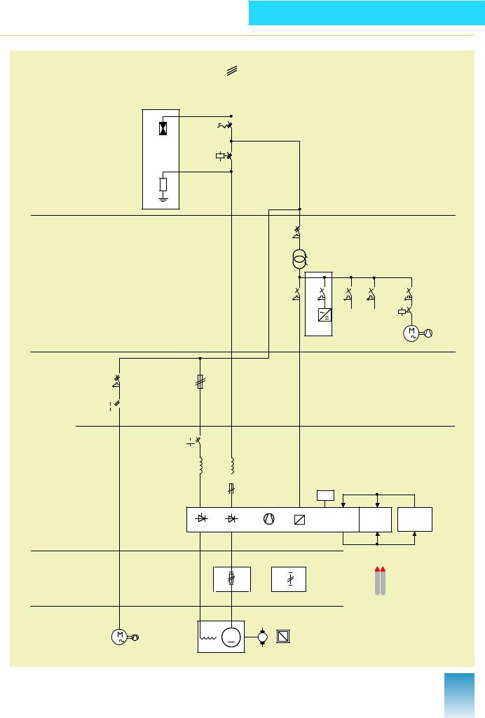
SIMOREG DC MASTER 6RM70
Digital Converter Cabinet Units
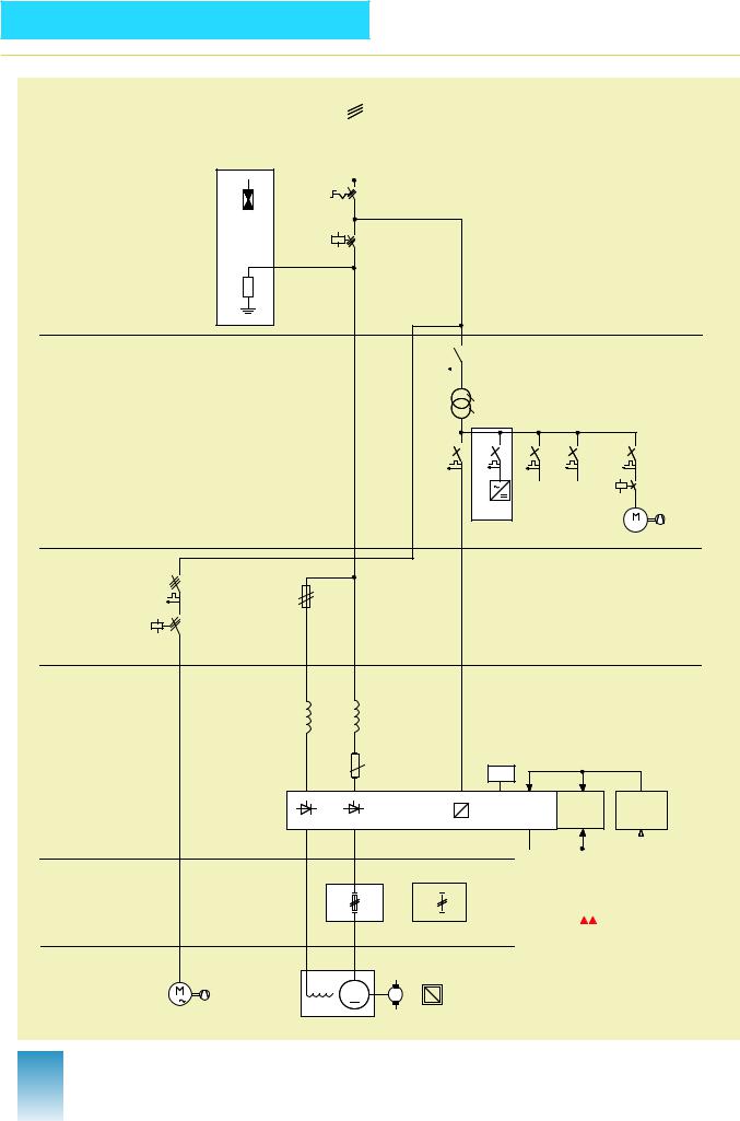
Block Diagram
■With SIMOREG DC MASTER 15 A to 125 A, 400 V
|
|
|
|
|
|
|
|
|
|
|
|
|
|
|
|
|
|
|
|
|
|
|
|
|
|
|
|
||
|
|
|
|
|
|
|
|
|
|
|
|
|
|
|
|
|
|
|
|
|

|
|
|
|
|
|
|
|
|
|
|
|

|
|
|
|
|
|
|
|
|
|
|
|
|
|
|
|
|
|
|
|

|
|
|
|
|
|
|
|
|
|
||||||||
|
|
|
|
|
|
|
|
|
|
||||||||
|
|
|
|
|
|
|
|
|
|
|
|
|
|
|
|||
|
|
|
|
|
|
|
|
|
|
|
|
||||||
|
|
|
|
|
|
|
|
|
|
|
|
||||||
|
|
|
|
|
|
|
|
|
|
|
|
||||||
|
|
|
|
|
|
||||||||||||
|
|
|
|
|
|
||||||||||||
|
|
|
|||||||||||||||
|
|
|
|
||||||||||||||
|
|||||||||||||||||
|
|
|
|||||||||||||||
|
|
|
|
|
|||||||||||||
|
|
|
|||||||||||||||
|
|
|
|
|
|
|
|
|
|
||||||||
|
|
|
|
|
|
|
|
|
|||||||||
|
|
|
|
|
|
|
|
|
|||||||||
|
|
|
|
|
|
|
|
|
|
||||||||
|
|
|
|
|
|
|
|
|
|
|
|
|
|
|
|
|
|
|
|
|
|
|
|
|
|
|
|
|
|
|
|
|
|
|
|
6 |
Siemens DA 22 · 2002 |
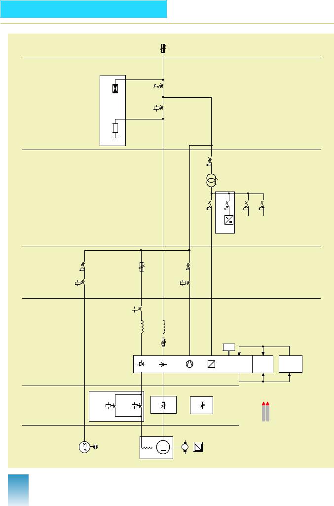
SIMOREG DC MASTER 6RM70
Digital Converter Cabinet Units
Block Diagram
■With SIMOREG DC MASTER 210 A and 280 A, 400 V
|
|
|
|
|
|
|
|
||
|
|
|
||
|
|
|
|
|
|
|
|
|
|
|
|
|
|
|
|
|
|
|
|
|
|
|
|
|
|
|
||
|
|
|
|
|
|
|
|
|
|


|
|
|
|
|
|
|
|
|
|
|
|
|
|
|
|
|
|
|
|
|
|
|
|
|
|
|
|
|
|
|
|
|
|
|
|
|
|
|
|
|
|
|
|
|
|
|
|
|
|
|
|
|
|
|
|
|
|
|
|
|
|
|
||
|
|
|
|
|
|
||||
|
|
|
|
|
|
|
|||
|
|
|
|
||||||
|
|
|
|
||||||
|
|
|
|
|
|
|
|||
|
|
|
|
|
|
|
|
|
|
|
|
|
|
|
|
|
|||
|
|
|
|
|
|
|
|
|
|
|
|
|
|
|
|
|
|
|
|
|
|
|
|
|
|
|
|
|
|
|
|
|
|
|
|
|
|
|
|
|
|
|
|
|
|
|
|
|
|
|
|
|
|
|
|
|
|
|
|
Siemens DA 22 · 2002 |
7 |
SIMOREG DC MASTER 6RM70
Digital Converter Cabinet Units
Block Diagram
■With SIMOREG DC MASTER 400 A to 850 A, 400 V
|
|
|
|
|
|
||
|
|||
|
|
|
|
|
|
|
|
|
|
|
|
|
|
|
|
|
|
|
|
|
|
||
|
|
|
|
|
|
|
|
|
|
|
|
|
|
|
|
|
|
|
|
|
|
|
|
|
|
|
|
|
|
|


|
|
|
|
|
|
|
|
|
|
|
|
|
|
|
|
|
|
|
|
|
|
|
||
|
|
|
|
|
||||
|
|
|
|
|
|
|
|
|
|
|
|
|
|
|
|
|
|
|
|
|
|
|
||||
|
|
|
|
|||||
|
|
|
|
|
|
|
|
|
|
|
|
|
|
|
|
|
|
|
|
|
|
|
|
|
||
|
|
|
|
|
|
|
|
|
|
|
|
|
|
|
|
|
|
|
|
|
|
|
|
|
|
|
|
|
|
|
|
|
|
|
|
8 |
Siemens DA 22 · 2002 |