

EN сталь / TKP EN 1993-1-4-2009
.pdfEN 1993-1-4: 2006 (E)
Table 2.2: Nominal values of fyb and fub for stainless steel bolts
Material |
Property class |
|
Yield strength |
Ultimate tensile strength |
|
to |
Range of sizes |
fyb |
fub |
||
groups |
|||||
EN ISO 3506 |
|
N/mm2 |
N/mm2 |
||
Austenitic |
50 |
≤ M 39 |
210 |
500 |
|
and |
|
|
|
|
|
70 |
≤ M 24 |
450 |
700 |
||
austenitic- |
|||||
|
|
|
|
||
80 |
≤ M 24 |
600 |
800 |
||
ferritic |
|||||
|
|
|
|
||
|
|
|
|
|
2.2.2Preloaded bolts
NOTE: High strength bolts made of stainless steel should not be used as preloaded bolts designed for a specific slip resistance, unless their acceptability in a particular application can be demonstrated from test results.
2.2.3Other types of mechanical fastener
(1)Requirements for other types of mechanical fasteners are given in EN 1993-1-3.
2.3 Welding consumables
(1)General requirements for welding consumables are given in EN 1993-1-8.
(2)In addition to the requirements of EN 1993-1-8, the welding electrodes should be capable of producing a weld with a corrosion resistance that is adequate for the service environment, provided that the correct welding procedure is used.
(3) The welding electrodes may be assumed to be adequate if the corrosion resistance of the deposited metal and weld metal is not less than that of the material to be welded.
NOTE: Professional advice is recommended on the selection of welding procedure for jointing stainless steels
3 Durability
(1)The requirements for durability given in Section 4 of EN 1993-1-1 should also be applied for stainless
steels.
(2)An appropriate grade of stainless steel should be selected according to the corrosion resistance required for the environment in which the structural members are to be used.
NOTE: Guidance on the selection of materials for corrosion resistance is given in Annex A.
(3) In cosmetic applications, the possible minor changes in surface appearance that might take place as a result of dirt deposits (which in adverse circumstances can create crevices and lead to surface micro-pitting) should also be taken into account. A suitable corrosion-resistant grade of stainless steel should be used to ensure that only superficial surface attack takes place within the design life of the component.
NOTE: Surface aspect features of hot rolled plates are described in EN 10163.
(4)If necessary, a suitable cleaning regime should be specified to maintain surface appearance.
(5)Although, under benign atmospheric exposure conditions, the requirements given in (3) can be satisfied by most stainless steels, expert advice should be sought if stainless steel is required to be exposed to environments that contain chemicals, including atmospheres associated with certain industrial processes, in swimming pool buildings, sea water and salt spray from road de-icing or the like.
6
EN 1993-1-4: 2006 (E)
NOTE: Additional information on design for corrosion control is given in Annex A.
4 Serviceability limit states
4.1 |
General |
(1) |
The requirements for serviceability given in Section 7 of EN 1993-1-1 should be applied for stainless |
steels. |
|
(2) |
Deflections in members should be estimated in accordance with 4.2. |
4.2 |
Determination of deflections |
(1) The effects of the non-linear stress-strain behaviour of stainless steels, and the effectiveness of the crosssection, should be taken into account in estimating deflections.
NOTE: Guidance for the description of the non-linear material behaviour of annealed material is given in Informative Annex C.
(2)The basic requirements for serviceability limit states are given in clause 3.4 of EN 1990.
NOTE: EN 1990 gives the appropriate combinations of actions to use in the following situations:
-for calculating deflections under permanent and/or variable actions;
-when long term deformations due to shrinkage, relaxation or creep need to be considered;
-if the appearance of the structure or the comfort of the user or functioning of machinery are being considered.
(3)The effective cross-section may conservatively be based on effective widths of compression elements in Class 4 cross-sections determined using 5.2.3. Alternatively, the more accurate method in 4.4(4) of EN 1993-1- 5 may be used.
(4)In the case of members subject to shear lag, the effective cross-section may be based on effective widths determined using 3.2 in EN 1993-1-5.
(5)Deflections should be estimated using the secant modulus of elasticity Es,ser determined taking account of the stresses in the member under the load combination for the relevant serviceability limit state and the orientation of the rolling direction. If the orientation of the rolling direction is not known, or cannot be ensured,
then the value for the longitudinal direction should be used. Alternatively, the FE-methods given in Annex C of EN 1993-1-5 may be used with the description of the non-linear material behaviour given in Annex C of this document.
(6)The value of the secant modulus of elasticity Es,ser may be obtained from:
Es , ser |
(Es,1 Es,2 ) |
|
(4.1) |
||
|
2 |
|
|
||
|
|
|
|
|
|
where: |
|
|
|
|
|
Es,1 |
is |
the secant modulus corresponding to the stress |
1 |
in the tension flange; |
|
Es,2 |
is |
the secant modulus corresponding to the stress |
1 |
in the compression flange. |
|
(7) The values of Es,1 and Es,2 for the appropriate serviceability design stress |
i,Ed,ser and rolling direction |
may be estimated using: |
|
7
EN 1993-1-4: 2006 (E)
E |
|
|
|
E |
|
|
|
|
|
|
|
|
|
|
|
|
|
s,i |
|
E |
|
|
n |
(4.2) |
||
|
|
|
|
|||||
|
1 |
0,002 |
|
i,Ed,ser |
|
|||
|
|
|
|
|
|
|||
|
i,Ed,ser |
|
fy |
|
||||
|
|
|
|
|
|
|||
with:
i= 1 or 2.
(8)The value of the coefficient n may be taken from Table 4.1.
NOTE: Annex C gives a method for evaluating n for grades other than those listed in Table 4.1.
(9)As a simplification, the variation of Es,ser along the length of the member may be neglected and the
minimum value of Es,ser for that member (corresponding to the maximum values of the stresses 1,Ed,ser and 2,Ed,ser in the member) may be used throughout its length.
Table 4.1: Values of n
|
Coefficient n |
||
Steel grade |
|
|
|
Longitudinal |
Transverse |
||
|
|||
|
direction |
direction |
|
1.4003 |
7 |
11 |
|
1.4016 |
6 |
14 |
|
1.4512 |
9 |
16 |
|
1.4301 |
|
|
|
1.4306 |
|
|
|
1.4307 |
6 |
8 |
|
1.4318 |
|
|
|
1.4541 |
|
|
|
1.4401 |
|
|
|
1.4404 |
|
|
|
1.4432 |
7 |
9 |
|
1.4435 |
|||
|
|
||
1.4539 |
|
|
|
1.4571 |
|
|
|
1.4462 |
5 |
5 |
|
1.4362 |
|
|
|
|
|
|
|
8
EN 1993-1-4: 2006 (E)
5 Ultimate limit states
5.1General
(1) The provisions given in Sections 5 and 6 of EN 1993-1-1 should be applied for stainless steels, except where modified or superseded by the special provisions given in this Part 1.4.
(2) |
The partial factors M as defined in 2.4.3 of EN 1993-1-1 are applied to the various characteristic values |
of resistance in this section as follows, see Table 5.1. |
|
Table 5.1: Partial factors
Resistance of cross-sections to excessive yielding including |
γM0 |
|
local buckling |
|
|
Resistance of members to instability assessed by member |
γM1 |
|
checks |
||
|
||
Resistance of cross-sections in tension to fracture |
γM2 |
|
Resistance of bolts, rivets, welds, pins and plates in bearing |
γM2 |
NOTE: M values may be determined in the National Annex. The following values are recommended
M0 = 1,1
M1 = 1,1
M2 = 1,25
(3)No rules are given for plastic global analysis.
NOTE: Plastic global analysis should not be used unless there is sufficient experimental evidence to ensure that the assumptions made in the calculations are representative of the actual behaviour of the structure. In particular there should be evidence that the joints are capable of resisting the increase in internal moments and forces due to strain hardening.
(4)P Joints subject to fatigue shall also satisfy the principles given in EN 1993-1-9.
(5) Where members may be subjected to significant deformation, account may be taken of the potential for enhanced strength gained through the work hardening properties of austenitic stainless steel. Where this work hardening increases the actions resisted by the members, the joints should be designed to be consistent with the increased member resistance, especially where capacity design is required.
5.2 Classification of cross-sections
5.2.1Maximum width-to-thickness ratios
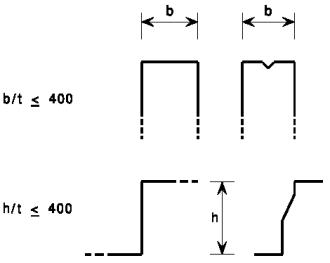
(1)The provisions for design by calculation given in this Part 1.4 may be assumed to apply to crosssections within the dimensional limits given in EN 1993-1-3, except that the overall width-to-thickness ratios b/t and h/t as defined in EN 1993-1-3 should not exceed 400, see Figure 5.1.
(2)If visual distortion of flat elements of the cross-section are unacceptable under the serviceability
loading, a limit of b/t 75 may be applied.
9
EN 1993-1-4: 2006 (E)
Figure 5.1: Maximum width-to-thickness ratios
5.2.2Classification of compression elements
(1) Compression elements of cross-sections should be classified as Class 1, 2 or 3 depending upon the limits specified in Table 5.2. Those compression elements that do not meet the criteria for Class 3 should be classified as Class 4 elements.
10
EN 1993-1-4: 2006 (E)
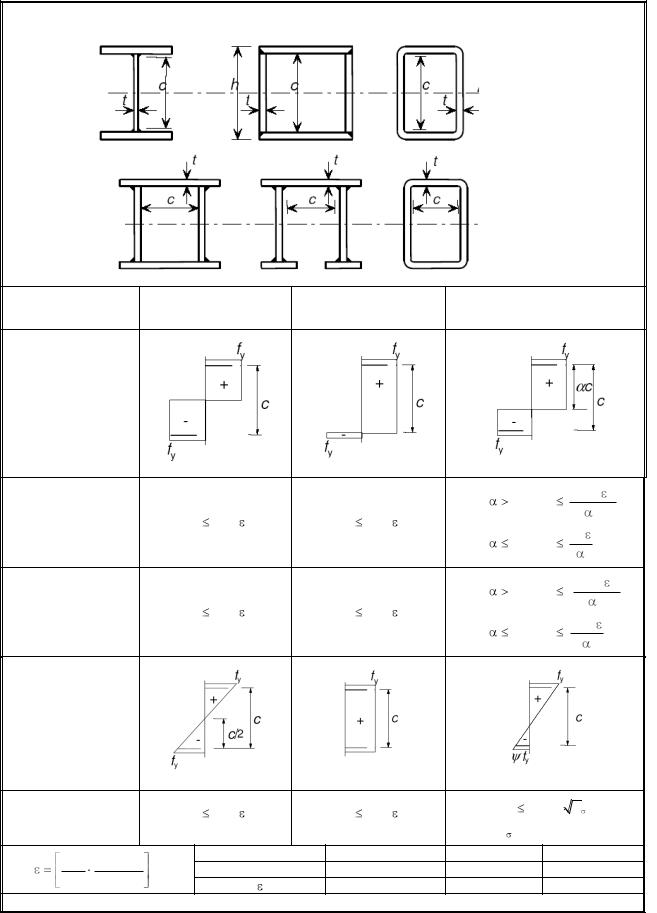
Table 5.2 (sheet 11 of 3): Maximum width-to-thickness ratios for compression parts
Internal compression parts
Axis of bending
Axis of bending
Class |
Part subject to |
Part subject to |
Part subject to bending and |
|
bending |
compression |
compression |
||
|
Stress distribution in parts (compression positive)
|
|
|
|
|
|
|
when |
0,5: c/t |
308 |
||
|
|
|
|
|
|
|
13 |
– 1 |
|||
1 |
|
|
c/t |
56,0 |
c/t |
25,7 |
|
|
|
||
|
|
|
|
|
|
|
|||||
|
|
|
|
|
|
|
when |
0,5: c/t |
28 |
|
|
|
|
|
|
|
|
|
|
|
|||
|
|
|
|
|
|
|
when |
0,5: c/t |
320 |
||
|
|
|
|
|
|
|
13 |
– 1 |
|||
2 |
|
|
c/t |
58,2 |
c/t |
26,7 |
|
|
|
||
|
|
|
|
|
|
|
|||||
|
|
|
|
|
|
|
when |
0,5: c/t |
29,1 |
||
|
|
|
|
|
|
|
|
|
|||
Stress |
|
|
|
|
|
|
|
|
|
|
|
distribution |
|
|
|
|
|
|
|
|
|
|
|
in parts |
|
|
|
|
|
|
|
|
|
|
|
(compression |
|
|
|
|
|
|
|
|
|
|
|
positive) |
|
|
|
|
|
|
|
|
|
|
|
3 |
|
|
c/t |
74,8 |
c/t |
30,7 |
c/t |
15,3e |
k |
|
|
|
|
|
|
|
|
|
|||||
|
|
|
|
|
|
|
For k see EN 1993-1-5 |
||||
235 |
E |
0,5 |
|
Grade |
|
1.4301 |
1.4401 |
|
1.4462 |
||
|
|
fy, N/мм2 |
|
210 |
220 |
|
|
460 |
|||
fy |
210 000 |
|
|
|
|
1,03 |
1,01 |
|
|
0,698 |
|
|
|
|
|
|
|
|
|
||||
Note: For hollow sections, |
c may conservatively be taken as (h-2t) or (b-2t). |
|
|
|
|
|
|||||
|
|
|
|
|
|
|
|
|
|
|
11 |

EN 1993-1-4: 2006 (E)
Table 5.2 (sheet 2 of 3): Maximum width-to-thickness ratios for compression parts
Outstand flanges
|
|
Part subject to |
Part subject to bending and compression |
||
Class |
Section type |
|
|
||
compression |
|
|
|||
Tip in compression |
Tip in tension |
||||
|
|
||||
|
|
|
|||
|
|
|
|
|
|
Stress |
|
|
|
|
|
|
|
|
|
|
|
distribution in |
|
|
|
|
|
|
|
|
|
|
|
parts |
|
|
|
|
|
|
|
|
|
|
|
(compression |
|
|
|
|
|
|
|
|
|
|
|
positive) |
|
|
|
|
|
|
|
|
|
|
|
|
|
Cold |
c/t |
10 |
|
c/t |
10 |
|
|
c/t |
10 |
|
|
formed |
|
|
|
|
|
||||
|
|
|
|
|
|
|
|
|
|
|
|
1 |
|
|
|
|
|
|
|
|
|
|
|
|
|
Welded |
c/t |
9 |
|
c/t |
9 |
|
|
c/t |
9 |
|
|
|
|
|
|
|
|||||
|
|
Cold |
c/t |
10,4 |
|
c/t |
10,4 |
|
|
c/t |
10,4 |
|
|
formed |
|
|
|
|
|
||||
|
|
|
|
|
|
|
|
|
|
|
|
2 |
|
|
|
|
|
|
|
|
|
|
|
|
|
Welded |
c/t |
9,4 |
|
c/t |
9,4 |
|
|
c/t |
9,4 |
|
|
|
|
|
|
|
|||||
Stress |
|
|
|
|
|
|
|
|
|
|
|
distribution in |
|
|
|
|
|
|
|
|
|
|
|
parts |
|
|
|
|
|
|
|
|
|
|
|
(compression |
|
|
|
|
|
|
|
|
|
|
|
positive) |
|
|
|
|
|
|
|
|
|
|
|
|
|
Cold |
c/t |
11,9 |
c/t |
18,1 |
k |
For k |
see EN 1993-1-5 |
||
|
|
formed |
|||||||||
3 |
|
|
|
|
|
|
|
|
|
|
|
|
|
|
|
|
|
|
|
|
|
|
|
|
|
Welded |
c/t |
11 |
c/t |
16,7 |
k |
For k |
see EN 1993-1-5 |
||
|
|
|
Grade |
1.4301 |
|
|
|
1.4401 |
|
1.4462 |
|
235 |
E |
0,5 |
|
|
|
|
|
|
|
|
|
|
fy, N/мм2 |
210 |
|
|
|
|
220 |
|
460 |
||
fy |
210 000 |
|
|
|
|
|
|
|
|
|
|
|
|
|
|
1,03 |
|
|
|
1,01 |
|
0,698 |
|
|
|
|
|
|
|
|
|
|
|
|
12 |
EN 1993-1-4: 2006 (E)
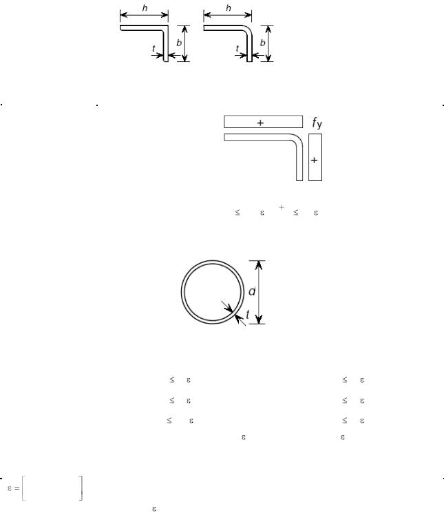
Table 5.2 (sheet 3 of 3): Maximum width-to-thickness ratios for compression parts
|
|
|
|
|
Angles |
|
|
|
|
|
|
|
|
|
|
|
Refer also to |
|
|
|
|
|
|
|
|
|
Does not apply to angles in |
||||||
“Outstand flanges” |
|
|
|
|
|
|
|
|
continuous contact with other |
|||||||
(see sheet 2 of 3) |
|
|
|
|
|
|
|
|
|
components |
||||||
|
|
|
|
|
|
|
|
|
|
|
|
|||||
|
Class |
|
|
|
Section in compression |
|
|
|
||||||||
|
|
|
|
|
|
|
|
|
|
|
|
|
|
|
|
|
|
Stress |
|
|
|
|
|
|
|
|
|
|
|
|
|
||
distribution |
|
|
|
|
|
|
|
|
|
|
|
|
|
|||
|
across |
|
|
|
|
|
|
|
|
|
|
|
|
|
||
|
section |
|
|
|
|
|
|
|
|
|
|
|
|
|
||
(compression |
|
|
|
|
|
|
|
|
|
|
|
|
|
|||
|
positive) |
|
|
|
|
|
|
|
|
|
|
|
|
|
||
|
|
|
|
|
|
|
|
|
|
|
|
|
|
|
|
|
|
|
3 |
|
|
|
h/t |
11,9 : |
b h |
9,1 |
|
|
|
||||
|
|
|
|
|
2t |
|
|
|
||||||||
|
|
|
|
|
|
|
|
|
|
|
|
|
|
|
|
|
|
|
|
|
|
|
|
|
|
|
|
|
|
|
|
||
|
|
|
|
|
Tubular sections |
|
|
|
|
|
|
|
||||
|
|
|
|
|
|
|
|
|
|
|
|
|
|
|
|
|
|
Class |
|
Section in bending |
|
|
|
|
|
|
Section in compression |
||||||
|
|
Up to 240 CHS |
|
|
|
|
|
|
||||||||
|
|
|
|
|
|
|
|
|
|
|
|
|
|
|
||
|
|
1 |
|
d/t 50 2 |
|
|
|
|
|
|
d/t 50 2 |
|
||||
|
|
|
|
|
|
|
|
|
|
|
|
|
|
|
||
|
|
2 |
|
d/t 70 2 |
|
|
|
|
|
|
d/t 70 2 |
|
||||
|
|
|
|
|
|
|
|
|
|
|
|
|
|
|
|
|
|
|
|
|
|
d/t 280 2 |
|
|
|
|
|
|
d/t |
|
90 2 |
|
|
|
|
3 |
|
NOTE: For d>240 mm and d/t >280 |
2 |
|
NOTE: For d/t >90 |
2 |
see EN 1993-1-6. |
|||||||
|
|
|
|
|
|
|
|
|||||||||
|
|
|
|
|
see EN 1993-1-6. |
|
|
|
|
|
|
|
|
|
|
|
|
|
|
|
|
|
|
|
|
|
|
|
|
||||
|
|
|
|
|
Grade |
|
1.4301 |
|
|
1.4401 |
1.4462 |
|||||
|
235 |
|
E |
0,5 |
|
|
|
|
|
|
|
|
|
|
|
|
|
|
fy, N/мм2 |
|
|
210 |
|
|
|
220 |
|
|
460 |
||||
|
fy |
210 000 |
|
|
|
|
|
|
||||||||
|
|
|
|
|
|
|
|
|
|
|
|
|
|
|||
|
|
|
|
|
1,03 |
|
|
|
1,01 |
|
|
0,698 |
||||
|
|
|
|
|
|
|
|
|
|
|
|
|
||||
|
|
|
|
|
|
|
|
|
|
|
|
|
|
|
|
|
13
EN 1993-1-4: 2006 (E)
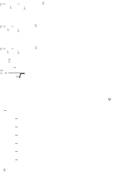
5.2.3Effective widths in Class 4 cross-sections
(1) In Class 4 cross-sections effective widths may be used to make necessary allowances for reductions in resistance due to the effects of local buckling using 4.4(1) to (5) of EN 1993-1-5, except that the reduction factor  should be taken as follows:
Cold formed or welded internal elements:
0,772 0,125 |
, but |
1 |
||||||
|
|
|
|
|
|
2 |
||
|
|
|
|
|
|
|||
|
|
|
|
|
||||
p |
p |
|
Cold formed outstand elements:
1 0,231 |
, but 1 |
||||||
|
|
|
|
|
2 |
|
|
|
|
|
|
|
|
||
|
|
|
|
|
|||
p p
Welded outstand elements:
1 0,242 |
, but 1 |
|||||
|
|
|
|
|
2 |
|
|
|
|
|
|
||
|
|
|
|
|||
p p
where p is the element slenderness defined as:
b / t
p
28,4  k
k
in which
t is the relevant thickness
k is the buckling factor corresponding to the stress ratio Table 4.2 in EN 1993-1-5 as appropriate
bis the relevant width as follows: b = d for webs (except RHS)
(5.1)
(5.2)
(5.3)
and boundary conditions from Table 4.1 or
b = flat element width for webs of RHS, which can conservatively be taken as h-2t
b = b for internal flange elements (except RHS)
b = flat element width for RHS flanges, which can conservatively be taken as b-2t
b = c for outstand flanges
b = h for equal leg angles and unequal leg angles is the material factor defined in Table 5.2.
5.2.4Effects of shear lag
(1)The effects of shear lag should be taken into account as specified in 3.3 of EN 1993-1-5.
5.3Resistance of cross-sections
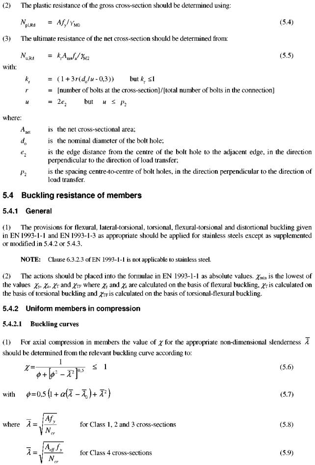
5.3.1 Tension resistance at holes for bolts
(1)The tension resistance of a cross-section should be taken as the lesser of the plastic resistance of the gross cross-section Npl,Rd and the ultimate resistance Nu,Rd of the net cross-section.
14
EN 1993-1-4: 2006 (E)
15