
- •Contents
- •1. Video and Image Processing Suite Overview
- •Release Information
- •Device Family Support
- •Latency
- •In-System Performance and Resource Guidance
- •Stall Behavior and Error Recovery
- •2. Interfaces
- •Video Formats
- •Avalon-ST Video Protocol
- •Video Data Packets
- •Static Parameters of Video Data Packets
- •Control Data Packets
- •Ancillary Data Packets
- •User-Defined and Altera-Reserved Packets
- •Packet Propagation
- •Transmission of Avalon-ST Video Over Avalon-ST Interfaces
- •Packet Transfer Examples
- •Avalon-MM Slave Interfaces
- •Specification of the Type of Avalon-MM Slave Interfaces
- •Avalon-MM Master Interfaces
- •Specification of the Type of Avalon-MM Master Interfaces
- •Buffering of Non-Image Data Packets in Memory
- •3. Getting Started
- •IP Catalog and Parameter Editor
- •Specifying IP Core Parameters and Options
- •Installing and Licensing IP Cores
- •OpenCore Plus IP Evaluation
- •4. Clocked Video Interface IP Cores
- •Control Port
- •Clocked Video Input Format Detection
- •Interrupts
- •Clocked Video Output Video Modes
- •Interrupts
- •Generator Lock
- •Underflow and Overflow
- •Timing Constraints
- •Handling Ancillary Packets
- •Modules for Clocked Video Input II IP Core
- •Clocked Video Interface Parameter Settings
- •Clocked Video Interface Signals
- •Clocked Video Interface Control Registers
- •5. 2D FIR Filter IP Core
- •Calculation Precision
- •Coefficient Precision
- •Result to Output Data Type Conversion
- •2D FIR IP Core Parameter Settings
- •2D FIR Filter Signals
- •2D FIR Filter Control Registers
- •6. Video Mixing IP Cores
- •Alpha Blending
- •Video Mixing Parameter Settings
- •Video Mixing Signals
- •Video Mixing Control Registers
- •7. Chroma Resampler IP Core
- •Horizontal Resampling (4:2:2)
- •Vertical Resampling (4:2:0)
- •Chroma Resampler Parameter Settings
- •Chroma Resampler Signals
- •8. Video Clipping IP Cores
- •Video Clipping Parameter Settings
- •Video Clipping Signals
- •Video Clipping Control Registers
- •9. Color Plane Sequencer IP Core
- •Combining Color Patterns
- •Rearranging Color Patterns
- •Splitting and Duplicating
- •Subsampled Data
- •Color Plane Sequencer Parameter Settings
- •Color Plane Sequencer Signals
- •10. Color Space Conversion IP Cores
- •Input and Output Data Types
- •Color Space Conversion
- •Result of Output Data Type Conversion
- •Color Space Conversion Parameter Settings
- •Color Space Conversion Signals
- •Color Space Conversion Control Registers
- •11. Control Synchronizer IP Core
- •Using the Control Synchronizer IP Core
- •Control Synchronizer Parameter Settings
- •Control Synchronizer Signals
- •Control Synchronizer Control Registers
- •12. Deinterlacing IP Cores
- •Deinterlacing Methods
- •Bob with Scanline Duplication
- •Bob with Scanline Interpolation
- •Weave
- •Motion-Adaptive
- •Sobel-Based HQ Mode
- •Pass-Through Mode for Progressive Frames
- •Frame Buffering
- •Frame Rate Conversion
- •Bandwidth Requirement Calculations for 10-bit YCbCr Video
- •Behavior When Unexpected Fields are Received
- •Handling of Avalon-ST Video Control Packets
- •Deinterlacing Parameter Settings
- •Deinterlacing Signals
- •Deinterlacing Control Registers
- •Design Guidelines for Broadcast Deinterlacer IP Core
- •13. Frame Reader IP Core
- •Single-Cycle Color Patterns
- •Frame Reader Output Pattern and Memory Organization
- •Frame Reader Parameter Settings
- •Frame Reader Signals
- •Frame Reader Control Registers
- •14. Frame Buffer IP Cores
- •Double Buffering
- •Triple Buffering
- •Locked Frame Rate Conversion
- •Handling of Avalon-ST Video Control Packets
- •Color Format
- •Frame Buffer Parameter Settings
- •Frame Buffer Signals
- •Frame Buffer Control Registers
- •15. Gamma Corrector IP Core
- •Gamma Corrector Parameter Settings
- •Gamma Corrector Signals
- •Gamma Corrector Control Registers
- •16. Interlacer IP Core
- •Interlacer Parameter Settings
- •Interlacer Signals
- •Interlacer Control Registers
- •17. Scaler II IP Core
- •Nearest Neighbor Algorithm
- •Bilinear Algorithm
- •Bilinear Algorithmic Description
- •Polyphase and Bicubic Algorithm
- •Double-Buffering
- •Polyphase Algorithmic Description
- •Choosing and Loading Coefficients
- •Edge-Adaptive Scaling Algorithm
- •Scaler II Parameter Settings
- •Scaler II Signals
- •Scaler II Control Registers
- •18. Video Switching IP Cores
- •Mixer Layer Switching
- •Video Switching Parameter Settings
- •Video Switching Signals
- •Video Switching Control Registers
- •19. Test Pattern Generator IP Cores
- •Test Pattern
- •Generation of Avalon-ST Video Control Packets and Run-Time Control
- •Test Pattern Generator Parameter Settings
- •Test Pattern Generator Signals
- •Test Pattern Generator Control Registers
- •20. Trace System IP Core
- •Trace System Parameter Settings
- •Trace System Signals
- •Operating the Trace System from System Console
- •Loading the Project and Connecting to the Hardware
- •Trace Within System Console
- •TCL Shell Commands
- •21. Avalon-ST Video Monitor IP Core
- •Packet Visualization
- •Monitor Settings
- •Avalon-ST Video Monitor Parameter Settings
- •Avalon-ST Video Monitor Signals
- •Avalon-ST Video Monitor Control Registers
- •Avalon-ST Video Class Library
- •Running the Tests
- •Video File Reader Test
- •Example Test Environment
- •Video Field Life Cycle
- •Constrained Random Test
- •Complete Class Reference
- •c_av_st_video_control
- •c_av_st_video_data
- •c_av_st_video_file_io
- •c_av_st_video_item
- •c_av_st_video_source_sink_base
- •c_av_st_video_sink_bfm_’SINK
- •c_av_st_video_source_bfm_’SOURCE
- •c_av_st_video_user_packet
- •c_pixel
- •Raw Video Data Format
- •Cadence Detection and Reverse Pulldown in the Deinterlacer II IP Core
- •Document Revision History
- •How to Contact Altera

Video Switching IP Cores 18
2015.01.23
UG-VIPSUITE |
Subscribe |
Send Feedback |
The Video Switching IP cores allow the connection of up to twelve input video streams to twelve output video streams.
You can configure the connections at run time through a control input.
Table 18-1: Video Switching IP Cores
IP Cores |
|
Feature |
|
|
|
Switch
Switch II
•Connects up to twelve input videos to 12 output videos.
•Does not duplicate or combine streams.
•Each output driven by one input and every input to the IP core can drive only one output. Any input can be disabled—not routed to an output, which stalls the input by pulling it's ready signal low.
•Supports 1 pixel per transmission.
•Connects up to twelve input videos to 12 output videos.
•Does not duplicate or combine streams.
•Each output driven by one input and every input to the IP core can drive only one output. Any input can be disabled—not routed to an output, which stalls the input by pulling it's ready signal low.
•Supports up to 4 pixels per transmission.
The routing configuration of the Video Switching IP cores is run-time configurable through the use of an Avalon-MM slave control port. You can write to the registers of the control port at anytime but the IP cores load the new values only when it is stopped. Stopping the IP cores causes all the input streams to be synchronized at the end of an Avalon-ST Video image packet.
You can load a new configuration in one of the following ways:
•Writing a 0 to the Go register, waiting for the Status register to read 0 and then writing a 1 to the Go register.
•Writing a 1 to the Output Switch register performs the same sequence but without the need for user intervention. This the recommended way to load a new configuration.
©2015 Altera Corporation. All rights reserved. ALTERA, ARRIA, CYCLONE, ENPIRION, MAX, MEGACORE, NIOS, QUARTUS and STRATIX words and logos are
trademarks of Altera Corporation and registered in the U.S. Patent and Trademark Office and in other countries. All other words and logos identified as trademarks or service marks are the property of their respective holders as described at www.altera.com/common/legal.html. Altera warrants performance of its semiconductor products to current specifications in accordance with Altera's standard warranty, but reserves the right to make changes to any products and services at any time without notice. Altera assumes no responsibility or liability arising out of the application or use of any information, product, or service described herein except as expressly agreed to in writing by Altera. Altera customers are advised to obtain the latest version of device specifications before relying on any published information and before placing orders for products or services.
ISO 9001:2008 Registered
www.altera.com
101 Innovation Drive, San Jose, CA 95134

18-2 |
Mixer Layer Switching |
UG-VIPSUITE |
|
2015.01.23 |
|||
|
|
Mixer Layer Switching
Layer switching is the ability to change the layer that a video stream is on, moving it in front of or behind the other video streams being mixed.
You can use the Video Switching IP cores in conjunction with the Alpha Blending Mixer and Control Synchronizer IP cores to perform run-time configurable layer switching in the Alpha Blending Mixer IP core.
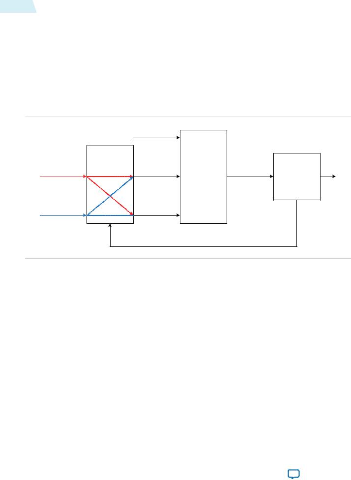
Figure 18-1: Example of a Layer Switching System
The figure below shows the system configuration used to achieve layer switching.
|
Background Layer |
Alpha Blending |
|
|
|
||
|
|
Mixer IP Core |
|
|
Switch IP Core |
Control |
|
|
|
||
Video Stream 1 |
Layer 1 |
Synchronizer |
|
IP Core |
|||
|
|
||
Video Stream 2 |
Layer 2 |
Avalon-MM |
|
Master |
|||
|
|
||
|
Avalon-MM |
|
|
|
Slave Control |
|
The Control Synchronizer IP core ensures that the switch of the video streams is performed at a safe place in the streams. Performing the switch when the Alpha Blending Mixer IP core is producing the start of an image packet, ensures that the video streams entering the Video Switching IP core are all on the same frame. They can then be switched on the next image end-of-packet without causing a deadlock situation between the Video Switching IP core and the Alpha Blending Mixer IP core.
The following sequence shows an example of layer switching:
1.Video Switching IP core—Write to the DoutN Output Control registers setting up the outputs. For example:
•Write 1 to address 3
•Write 2 to address 4
2.Video Switching IP core—Enable the function by writing 1 to address 0.
3.Video Switching IP core—Write to the DoutN Output Control registers to switch the outputs. For example:
•Write 2 to address 3
•Write 1 to address 4
4.Control Synchronizer IP core—Set up the IP core to write a 1 to the Video Switching IP core’s Output Switch register on the next start of an image packet.
Altera Corporation |
Video Switching IP Cores |
|
|
Send Feedback

UG-VIPSUITE |
Video Switching Parameter Settings |
18-3 |
|
2015.01.23 |
|||
|
|
Video Switching Parameter Settings
Table 18-2: Video Switching Parameter Settings
Parameter |
|
Value |
|
Description |
|
|
|
|
|
Bits per pixel per color plane |
|
4–20, Default = 8 |
|
Select the number of bits per pixel (per color |
|
|
|
|
plane). |
|
|
|
|
|
Number of color planes |
|
1–3, Default = 3 |
|
Select the number of color planes. |
|
|
|
|
|
Color planes are in parallel |
|
On or Off |
|
• Turn on to set colors planes in parallel. |
|
|
|
|
• Turn off to set colors planes in sequence. |
|
|
|
|
|
Number of inputs |
|
1–12, Default = 2 |
|
Select the number of Avalon-ST video inputs |
|
|
|
|
to the IP core (din and alpha_in). |
Number of outputs |
|
1–12, Default = 2 |
|
Select the number of Avalon-ST video |
|
|
|
|
outputs from the IP core(dout and alpha_ |
|
|
|
|
out). |
|
|
|
|
|
Enable alpha channel |
|
On or Off |
|
Turn on to enable the alpha ports. |
|
|
|
|
Note: Available only for Switch IP core. |
|
|
|
|
|
Alpha bits per pixel |
|
2, 4, 8 |
|
Select the number of bits used to represent |
|
|
|
|
the alpha coefficient. |
|
|
|
|
Note: Available only for Switch IP core. |
|
|
|
|
|
Number of pixels in parallel |
|
1, 2, or 4 |
|
Specify the number of pixels transmitted or |
|
|
|
|
received in parallel. |
|
|
|
|
Note: Available only for Switch II IP |
|
|
|
|
core. |
|
|
|
|
|
Video Switching Signals
Table 18-3: Video Switching Signals
The table below lists the signals for Switch and Switch II IP cores.
|
Signal |
|
Direction |
|
Description |
|
|
|
|
|
|
|
|
|
|
|
reset |
|
Input |
|
The IP core asynchronously resets when you assert this |
||
|
|
|
|
|
signal. You must deassert this signal synchronously to the |
||
|
|
|
|
|
rising edge of the clock signal. |
||
|
|
|
|
|
|
|
|
|
clock |
|
Input |
|
The main system clock. The IP core operates on the rising |
|
|
|
|
|
|
|
edge of this signal. |
|
|
|
din_N_data |
|
Input |
|
din_N port Avalon-ST data bus. This bus enables the |
|
|
|
|
|
|
|
transfer of pixel data into the IP core. |
||
|
|
|
|
|
|
|
|
|
|
|
|
|
|
||
Video Switching IP Cores |
|
|
|
|
Altera Corporation |
||
|
Send Feedback |
|
|
|
|
|
|

18-4 |
Video Switching Signals |
|
|
|
UG-VIPSUITE |
||
|
|
2015.01.23 |
|||||
|
|
|
|
|
|||
|
|
|
|
|
|
|
|
|
|
Signal |
|
Direction |
|
Description |
|
|
|
|
|
|
|
|
|
|
|
din_N_endofpacket |
|
Input |
|
din_N port Avalon-ST endofpacket signal. This signal |
|
|
|
|
|
|
|
marks the end of an Avalon-ST packet. |
|
|
|
din_N_ready |
|
Output |
|
din_N port Avalon-ST ready signal. The IP core asserts |
|
|
|
|
|
|
|
this signal when it is able to receive data. |
|
|
|
|
|
|
|
|
|
|
|
din_N_startofpacket |
|
Input |
|
din_N port Avalon-ST startofpacket signal. This signal |
|
|
|
|
|
|
|
marks the start of an Avalon-ST packet. |
|
|
|
din_N_valid |
|
Input |
|
din_N port Avalon-ST valid signal. This signal identifies |
|
|
|
|
|
|
|
the cycles when the port must input data. |
|
|
|
|
|
|
|
|
|
|
|
dout_N_data |
|
Output |
|
dout port Avalon-ST data bus. This bus enables the |
|
|
|
|
|
|
|
transfer of pixel data out of the IP core. |
|
|
|
dout_N_endofpacket |
|
Output |
|
dout_N port Avalon-ST endofpacket signal. This signal |
|
|
|
|
|
|
|
marks the end of an Avalon-ST packet. |
|
|
|
|
|
|
|
|
|
|
|
dout_N_ready |
|
Input |
|
dout_N port Avalon-ST ready signal. The downstream |
|
|
|
|
|
|
|
device asserts this signal when it is able to receive data. |
|
|
|
dout_N_startofpacket |
|
Output |
|
dout_N port Avalon-ST startofpacket signal. This signal |
|
|
|
|
|
|
|
marks the start of an Avalon-ST packet. |
|
|
|
|
|
|
|
|
|
|
|
dout_N_valid |
|
Output |
|
dout_N port Avalon-ST valid signal. The IP core asserts |
|
|
|
|
|
|
|
this signal when it produces data. |
|
|
|
|
|
|
|
|
|
Table 18-4: Alpha Signals for Switch IP Core
The table below lists the signals that are available only when you turn Enable alpha channel in the Switch parameter editor.
Signal |
|
Direction |
|
Description |
|
|
|
|
|
alpha_in_N_data |
Input |
alpha_in_N port Avalon-ST data bus. This bus enables |
|
|
the transfer of pixel data into the IP core. |
|
|
|
alpha_in_N_endofpacket |
Input |
alpha_in_N port Avalon-ST endofpacket signal. This |
|
|
signal marks the end of an Avalon-ST packet. |
alpha_in_N_ready |
Output |
alpha_in_N port Avalon-ST ready signal. The IP core |
|
|
asserts this signal when it is able to receive data. |
|
|
|
alpha_in_N_startofpacket |
Input |
alpha_in_N port Avalon-ST startofpacket signal. This |
|
|
signal marks the start of an Avalon-ST packet. |
alpha_in_N_valid |
Input |
alpha_in_N port Avalon-ST valid signal. This signal |
|
|
identifies the cycles when the port must insert data. |
|
|
|
alpha_out_N_data |
Output |
alpha_out port Avalon-ST data bus. This bus enables the |
|
|
transfer of pixel data out of the IP core. |
alpha_out_N_endofpacket |
Output |
alpha_out port Avalon-ST endofpacket signal. This |
|
|
signal marks the end of an Avalon-ST packet. |
|
|
|
Altera Corporation |
Video Switching IP Cores |
|
|
Send Feedback