
- •Contents
- •1. Video and Image Processing Suite Overview
- •Release Information
- •Device Family Support
- •Latency
- •In-System Performance and Resource Guidance
- •Stall Behavior and Error Recovery
- •2. Interfaces
- •Video Formats
- •Avalon-ST Video Protocol
- •Video Data Packets
- •Static Parameters of Video Data Packets
- •Control Data Packets
- •Ancillary Data Packets
- •User-Defined and Altera-Reserved Packets
- •Packet Propagation
- •Transmission of Avalon-ST Video Over Avalon-ST Interfaces
- •Packet Transfer Examples
- •Avalon-MM Slave Interfaces
- •Specification of the Type of Avalon-MM Slave Interfaces
- •Avalon-MM Master Interfaces
- •Specification of the Type of Avalon-MM Master Interfaces
- •Buffering of Non-Image Data Packets in Memory
- •3. Getting Started
- •IP Catalog and Parameter Editor
- •Specifying IP Core Parameters and Options
- •Installing and Licensing IP Cores
- •OpenCore Plus IP Evaluation
- •4. Clocked Video Interface IP Cores
- •Control Port
- •Clocked Video Input Format Detection
- •Interrupts
- •Clocked Video Output Video Modes
- •Interrupts
- •Generator Lock
- •Underflow and Overflow
- •Timing Constraints
- •Handling Ancillary Packets
- •Modules for Clocked Video Input II IP Core
- •Clocked Video Interface Parameter Settings
- •Clocked Video Interface Signals
- •Clocked Video Interface Control Registers
- •5. 2D FIR Filter IP Core
- •Calculation Precision
- •Coefficient Precision
- •Result to Output Data Type Conversion
- •2D FIR IP Core Parameter Settings
- •2D FIR Filter Signals
- •2D FIR Filter Control Registers
- •6. Video Mixing IP Cores
- •Alpha Blending
- •Video Mixing Parameter Settings
- •Video Mixing Signals
- •Video Mixing Control Registers
- •7. Chroma Resampler IP Core
- •Horizontal Resampling (4:2:2)
- •Vertical Resampling (4:2:0)
- •Chroma Resampler Parameter Settings
- •Chroma Resampler Signals
- •8. Video Clipping IP Cores
- •Video Clipping Parameter Settings
- •Video Clipping Signals
- •Video Clipping Control Registers
- •9. Color Plane Sequencer IP Core
- •Combining Color Patterns
- •Rearranging Color Patterns
- •Splitting and Duplicating
- •Subsampled Data
- •Color Plane Sequencer Parameter Settings
- •Color Plane Sequencer Signals
- •10. Color Space Conversion IP Cores
- •Input and Output Data Types
- •Color Space Conversion
- •Result of Output Data Type Conversion
- •Color Space Conversion Parameter Settings
- •Color Space Conversion Signals
- •Color Space Conversion Control Registers
- •11. Control Synchronizer IP Core
- •Using the Control Synchronizer IP Core
- •Control Synchronizer Parameter Settings
- •Control Synchronizer Signals
- •Control Synchronizer Control Registers
- •12. Deinterlacing IP Cores
- •Deinterlacing Methods
- •Bob with Scanline Duplication
- •Bob with Scanline Interpolation
- •Weave
- •Motion-Adaptive
- •Sobel-Based HQ Mode
- •Pass-Through Mode for Progressive Frames
- •Frame Buffering
- •Frame Rate Conversion
- •Bandwidth Requirement Calculations for 10-bit YCbCr Video
- •Behavior When Unexpected Fields are Received
- •Handling of Avalon-ST Video Control Packets
- •Deinterlacing Parameter Settings
- •Deinterlacing Signals
- •Deinterlacing Control Registers
- •Design Guidelines for Broadcast Deinterlacer IP Core
- •13. Frame Reader IP Core
- •Single-Cycle Color Patterns
- •Frame Reader Output Pattern and Memory Organization
- •Frame Reader Parameter Settings
- •Frame Reader Signals
- •Frame Reader Control Registers
- •14. Frame Buffer IP Cores
- •Double Buffering
- •Triple Buffering
- •Locked Frame Rate Conversion
- •Handling of Avalon-ST Video Control Packets
- •Color Format
- •Frame Buffer Parameter Settings
- •Frame Buffer Signals
- •Frame Buffer Control Registers
- •15. Gamma Corrector IP Core
- •Gamma Corrector Parameter Settings
- •Gamma Corrector Signals
- •Gamma Corrector Control Registers
- •16. Interlacer IP Core
- •Interlacer Parameter Settings
- •Interlacer Signals
- •Interlacer Control Registers
- •17. Scaler II IP Core
- •Nearest Neighbor Algorithm
- •Bilinear Algorithm
- •Bilinear Algorithmic Description
- •Polyphase and Bicubic Algorithm
- •Double-Buffering
- •Polyphase Algorithmic Description
- •Choosing and Loading Coefficients
- •Edge-Adaptive Scaling Algorithm
- •Scaler II Parameter Settings
- •Scaler II Signals
- •Scaler II Control Registers
- •18. Video Switching IP Cores
- •Mixer Layer Switching
- •Video Switching Parameter Settings
- •Video Switching Signals
- •Video Switching Control Registers
- •19. Test Pattern Generator IP Cores
- •Test Pattern
- •Generation of Avalon-ST Video Control Packets and Run-Time Control
- •Test Pattern Generator Parameter Settings
- •Test Pattern Generator Signals
- •Test Pattern Generator Control Registers
- •20. Trace System IP Core
- •Trace System Parameter Settings
- •Trace System Signals
- •Operating the Trace System from System Console
- •Loading the Project and Connecting to the Hardware
- •Trace Within System Console
- •TCL Shell Commands
- •21. Avalon-ST Video Monitor IP Core
- •Packet Visualization
- •Monitor Settings
- •Avalon-ST Video Monitor Parameter Settings
- •Avalon-ST Video Monitor Signals
- •Avalon-ST Video Monitor Control Registers
- •Avalon-ST Video Class Library
- •Running the Tests
- •Video File Reader Test
- •Example Test Environment
- •Video Field Life Cycle
- •Constrained Random Test
- •Complete Class Reference
- •c_av_st_video_control
- •c_av_st_video_data
- •c_av_st_video_file_io
- •c_av_st_video_item
- •c_av_st_video_source_sink_base
- •c_av_st_video_sink_bfm_’SINK
- •c_av_st_video_source_bfm_’SOURCE
- •c_av_st_video_user_packet
- •c_pixel
- •Raw Video Data Format
- •Cadence Detection and Reverse Pulldown in the Deinterlacer II IP Core
- •Document Revision History
- •How to Contact Altera

UG-VIPSUITE 2015.01.23
Polyphase and Bicubic Algorithm |
17-3 |
precision of each error variable is determined by the number of fraction bits chosen by the user, Bfh and Bfv, respectively.
Their values can be calculated using the following equation:
The sum is then weighted proportionally to these errors.
Note: Because these values are measured from the top-left pixel, the weights for this pixel are one minus the error.
That is, in fixed-point precision: and
The sum is then:
Polyphase and Bicubic Algorithm
Polyphase and bicubic algorithms offer the best image quality, but use more resources than the other modes of the Scaler II.
The polyphase and bicubic algorithms allow scaling to be performed in such a way as to preserve sharp edges, but without losing the smooth interpolation effect on graduated areas. For down scaling, a long polyphase filter can reduce aliasing effects.
The bicubic and polyphase algorithms use different mathematics to derive their filter coefficients. The implementation of the bicubic algorithm is just the polyphase algorithm with four vertical and four horizontal taps. In the following discussion, all comments relating to the polyphase algorithm are applicable to the bicubic algorithm assuming 4×4 taps.
Scaler II IP Core |
Altera Corporation |
|
|
Send Feedback

17-4 |
Polyphase and Bicubic Algorithm |
UG-VIPSUITE |
|
2015.01.23 |
|||
|
|
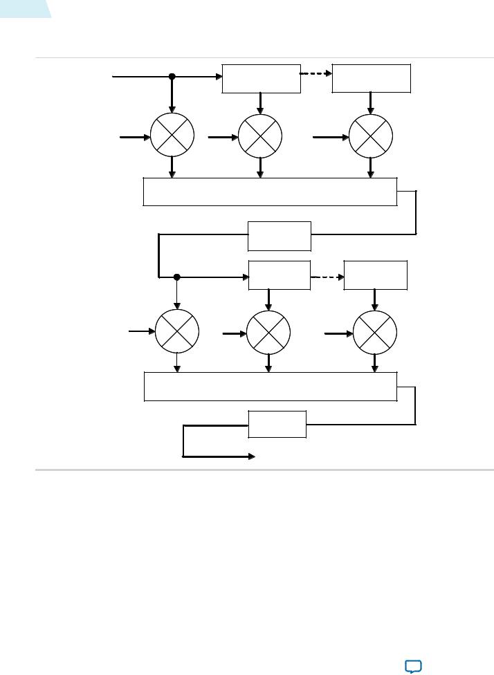
Figure 17-1: Polyphase Mode Scaler Block Diagram
The figure below shows the flow of data through an instance of the Scaler II in polyphase mode.
|
Line Buffer |
Line Buffer |
|
Delay |
Delay |
Cv 0 |
Cv 1 |
Cv Nv |
∑
|
Bit Narrowing |
|
|
Register Delay |
Register Delay |
Ch 0 |
Ch 1 |
Ch Nh |
∑
Bit Narrowing
Data from multiple lines of the input image are assembled into line buffers–one for each vertical tap. These data are then fed into parallel multipliers, before summation and possible loss of precision. The results are gathered into registers–one for each horizontal tap. These are again multiplied and summed before precision loss down to the output data bit width.
Note: The progress of data through the taps (line buffer and register delays) and the coefficient values in the multiplication are controlled by logic that is not present in the diagram.
Consider the following for an instance of the polyphase scaler.
Altera Corporation |
Scaler II IP Core |
|
|
Send Feedback

UG-VIPSUITE 2015.01.23
Double-Buffering 17-5
•Nv = vertical taps
•Nh = horizontal taps
•Bdata = bit width of the data samples
•Bv = bit width of the vertical coefficients
•Bh = bit width of the horizontal coefficients
•Pv = user-defined number of vertical phases for each coefficient set (must be a power of 2)
•Ph = user-defined number of horizontal phases for each coefficient set (must be a power of 2)
•Cv = number of vertical coefficient banks
•Ch = number of horizontal coefficient banks
The total number of multipliers is Nv + Nh per channel in parallel. The width of each vertical multiplier is max(Bdata, Bv)
The width of each horizontal multiplier is the maximum of the horizontal coefficient width, Bh, and the bit width of the horizontal kernel, Bkh.
The bit width of the horizontal kernel determines the precision of the results of vertical filtering and is user-configurable.
The memory requirement is Nv line-buffers plus vertical and horizontal coefficient banks. As in the nearest-neighbor and bilinear methods, each line buffer is the same size as one line from the clipped input image.
The vertical coefficient banks are stored in memory that is Bv bits wide and Pv×Nv×Cv words deep. The horizontal coefficient banks are stored in memory that is Bh×Nh bits wide and Ph×Ch words deep. For each coefficient type, the Quartus II software maps these appropriately to physical on-chip RAM or logic elements as constrained by the width and depth requirements.
Note: If the horizontal and vertical coefficients are identical, they are stored in the horizontal memory (as defined above). If you turn on Share horizontal /vertical coefficients in the parameter editor, this setting is forced even when the coefficients are loaded at run time.
Double-Buffering
Using multiple coefficient banks allows double-buffering, fast swapping, or direct writing to the scaler’s coefficient memories. he coefficient bank to be read during video data processing and the bank to be written by the Avalon-MM interface are specified separately at run time.
Choosing to have more memory banks allows for each bank to contain coefficients for a specific scaling ratio and for coefficient changes to be accomplished very quickly by changing the read bank. Alterna tively, for memory-sensitive applications, use a single bank and coefficient writes have an immediate effect on data processing.
To accomplish double-buffering:
1.Select two memory banks at compile time.
2.At start-up run time, select a bank to write into (for example 0) and write the coefficients.
3.Set the chosen bank (0) to be the read bank for the Scaler II IP core, and start processing.
4.For subsequent changes, write to the unused bank (1) and swap the read and write banks between frames.
Scaler II IP Core |
Altera Corporation |
|
|
Send Feedback

17-6 |
Polyphase Algorithmic Description |
UG-VIPSUITE |
|
2015.01.23 |
|||
|
|
Polyphase Algorithmic Description
The algorithmic operations of the polyphase scaler can be modeled using a frame-based method.
The filtering part of the polyphase scaler works by passing a windowed sinc function over the input data.
•For up scaling, this function performs interpolation.
•For down scaling, it acts as a low-pass filter to remove high-frequency data that would cause aliasing in the smaller output image.
During the filtering process, the mid-point of the sinc function must be at the mid-point of the pixel to output. This is achieved by applying a phase shift to the filtering function.
If a polyphase filter has Nv vertical taps and Nh horizontal taps, the filter is a Nv×Nh square filter.
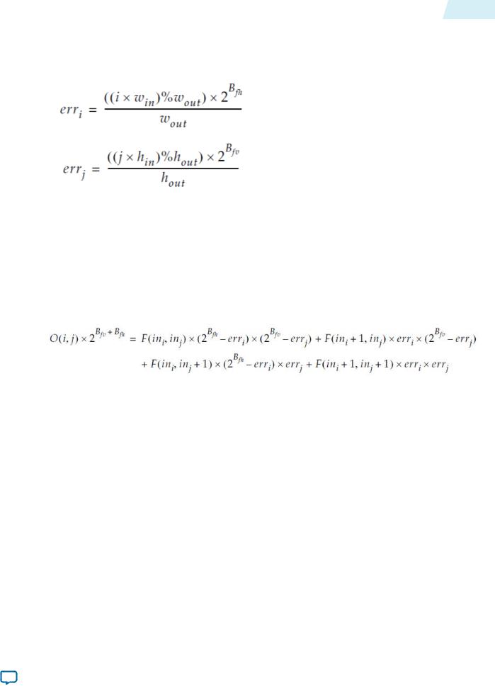
Counting the coordinate space of the filter from the top-left corner, (0, 0), the mid-point of the filter lies at ((Nv–1)/2, (Nh–1)/2). As in the bilinear case, to produce an output pixel at (i, j), the mid-point of the
kernel is placed at where ini and inj are calculated using the algorithmic description equations. The difference between the real and integer solutions to these equations determines the position of the filter function during scaling.
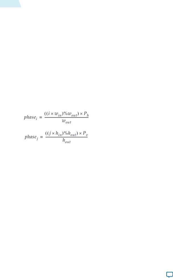
The filter function is positioned over the real solution by adjusting the function’s phase:
The results of the vertical filtering are then found by taking the set of coefficients from phasej and applying them to each column in the square filter. Each of these Nh results is then divided down to fit in the number of bits chosen for the horizontal kernel. The horizontal kernel is applied to the coefficients from phasei, to produce a single value. This value is then divided down to the output bit width before being written out as a result.
Choosing and Loading Coefficients
The filter coefficients, which the polyphase mode of the scaler uses, may be specified at compile time or at run time.
At compile time, you can select the coefficients from a set of Lanczos-windowed sinc functions, or loaded from a comma-separated variable (CSV) file.
At run time, you specify the coefficients by writing to the Avalon-MM slave control port.
When the coefficients are read at run time, they are checked once per frame and double-buffered so that they can be updated as the IP core processes active data without causing corruption.
Altera Corporation |
Scaler II IP Core |
|
|
Send Feedback

UG-VIPSUITE |
Choosing and Loading Coefficients |
17-7 |
|
2015.01.23 |
|||
|
|
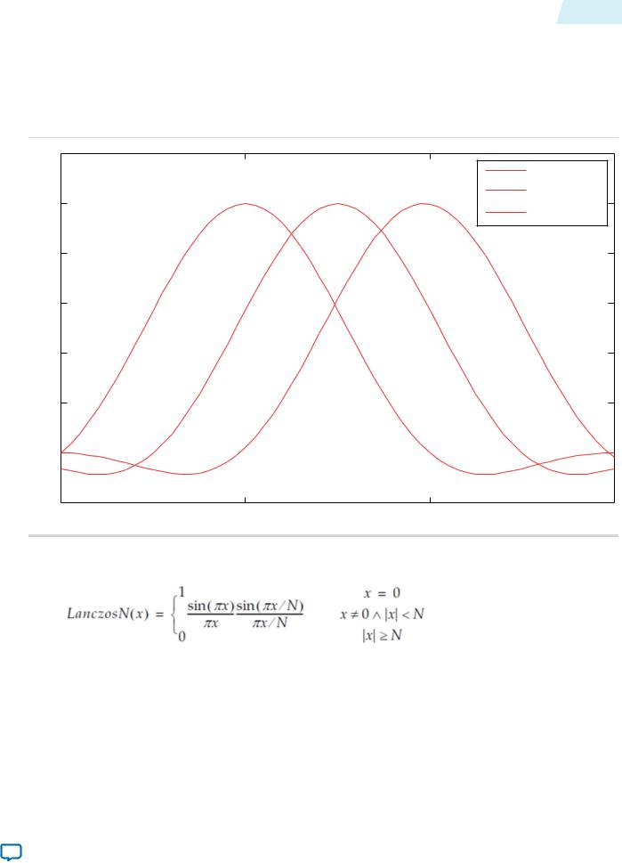
Figure 17-2: Lanczos 2 Function at Various Phases
The figure below shows how a 2-lobe Lanczos-windowed sinc function (usually referred to as Lanczos 2) is sampled for a 4-tap vertical filter.
Note: The two lobes refer to the number of times the function changes direction on each side of the central maxima, including the maxima itself.
1. |
2 |
|
phase(0) |
|
|
|
|
||
|
1 |
|
phase( |
P v /2) |
|
|
phase( |
P v −1) |
|
|
|
|
||
0. |
8 |
|
|
|
0. |
6 |
|
|
|
0. |
4 |
|
|
|
0. |
2 |
|
|
|
|
0 |
|
|
|
−0. |
2 0 |
1 |
2 |
3 |
The class of Lanczos N functions is defined as:
As can be seen in the figure, phase 0 centers the function over tap 1 on the x-axis. By the equation above, this is the central tap of the filter.
•Further phases move the mid-point of the function in 1/Pv increments towards tap 2.
•The filtering coefficients applied in a 4-tap scaler for a particular phase are samples of where the function with that phase crosses 0, 1, 2, 3 on the x-axis.
•The preset filtering functions are always spread over the number of taps given. For example, Lanczos 2 is defined over the range –2 to +2, but with 8 taps the coefficients are shifted and spread to cover 0 to 7.
Scaler II IP Core |
Altera Corporation |
|
|
Send Feedback