

Interfaces 2
2015.01.23
UG-VIPSUITE |
Subscribe |
Send Feedback |
The IP cores in the Video and Image Processing Suite use standard interfaces for data input and output, control input, and access to external memory. These standard interfaces ensure that video systems can be quickly and easily assembled by connecting IP cores together.
The IP cores use the following types of interface:
•Avalon-ST interface—a streaming interface that supports backpressure. The Avalon-ST Video protocol transmits video and configuration data. This interface type allows the simple creation of video processing data paths, where IP cores can be connected together to perform a series of video processing functions.
•Avalon-MM slave interface—provides a means to monitor and control the properties of the IP cores.
•Avalon-MM master interface—when the IP cores require access to a slave interface, for example an external memory controller.
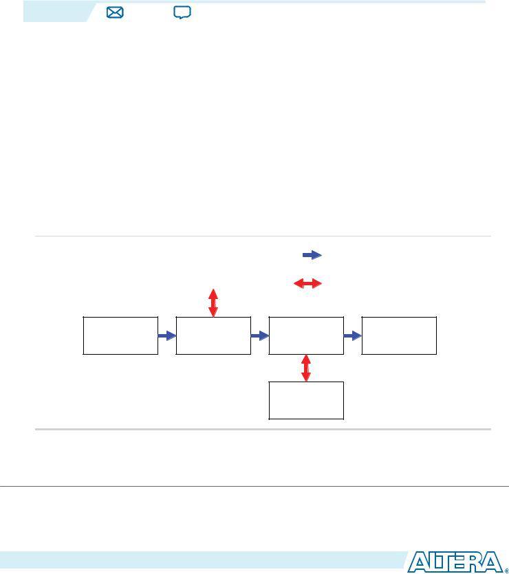
Figure 2-1: Abstracted Block Diagram Showing Avalon-ST and Avalon-MM Connections
The figure below shows an example of video processing data paths using the Avalon-ST and Avalon-MM interfaces.
DDR 2 SDRAM |
Avalon ST Connection |
Controller with UniPHY |
|
IP Core |
Avalon MM Master to Slave Connection |
|
Clocked Video Input |
Deinterlacer |
Scaler II |
Clocked Video Output |
IP Core |
IP Core |
IP Core |
IP Core |
Nios II
Processor
Note: This abstracted view is similar to that provided in the Qsys tool, where interface wires are grouped together as single connections.
© 2015 Altera Corporation. All rights reserved. ALTERA, ARRIA, CYCLONE, ENPIRION, MAX, MEGACORE, NIOS, QUARTUS and STRATIX words and logos are trademarks of Altera Corporation and registered in the U.S. Patent and Trademark Office and in other countries. All other words and logos identified as trademarks or service marks are the property of their respective holders as described at www.altera.com/common/legal.html. Altera warrants performance of its semiconductor products to current specifications in accordance with Altera's standard warranty, but reserves the right to make changes to any products and services at any time without notice. Altera assumes no responsibility or liability arising out of the application or use of any information, product, or service described herein except as expressly agreed to in writing by Altera. Altera customers are advised to obtain the latest version of device specifications before relying on any published information and before placing orders for products or services.
ISO 9001:2008 Registered
www.altera.com
101 Innovation Drive, San Jose, CA 95134

2-2 |
Video Formats |
UG-VIPSUITE |
|
2015.01.23 |
|||
|
|
The Clocked Video Input and Clocked Video Output IP cores also have external interfaces that support clocked video standards. These IP cores can connect between the function’s Avalon-ST interfaces and functions using clocked video standards such as BT.656.
Related Information
Avalon Interface Specifications
Provides more information about these interface types.
Video Formats
The Clocked Video Output IP cores create clocked video formats, and Clocked Video Input IP cores accept clocked video formats.
The IP cores create and accept the following formats:
•Video with synchronization information embedded in the data (in BT656 or BT1120 format)
•Video with separate synchronization (H sync, V sync) signals
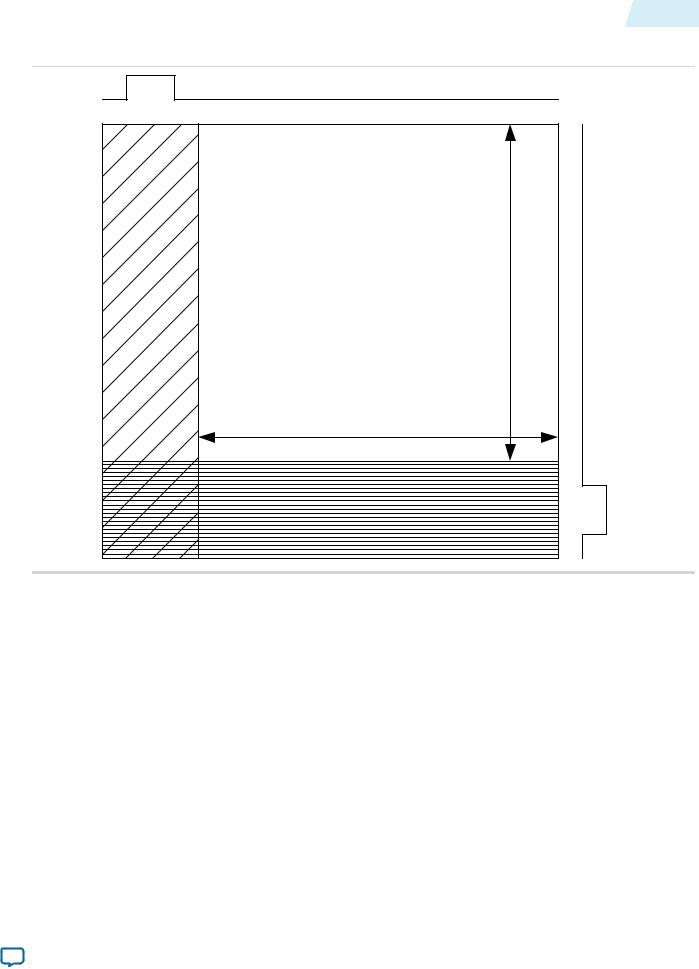
The CVO IP cores create a video frame consisting of horizontal and vertical blanking (containing syncs) and areas of active picture (taken from the Avalon-ST Video input).
•Video with synchronization information embedded in the data (in BT656 or BT1120 format)
•Video with separate synchronization (H sync, V sync) signals
Altera Corporation |
Interfaces |
|
|
Send Feedback
UG-VIPSUITE |
Video Formats |
2-3 |
|
2015.01.23 |
|||
|
|
Figure 2-2: Progressive Frame Format
|
Horizontal Sync |
|
|
F0 Active Picture |
Height |
|
|
|
Blanking |
|
SyncVertical |
Horizontal |
Width |
|
|
|
|
|
Vertical Blanking |
|
Interfaces |
Altera Corporation |
|
|
Send Feedback
2-4 |
Video Formats |
UG-VIPSUITE |
|
2015.01.23 |
|||
|
|
Figure 2-3: Interlaced Frame Format
|
Horizontal Sync |
|
|
|
F0 Active Picture |
Height |
|
|
Width |
|
|
|
|
|
|
|
|
|
Field |
HorizontalBlanking |
F0 Vertical Blanking |
|
|
F1 Active Picture |
Height |
SyncVertical |
|
|
|
|
|
|
Width |
|
|
|
Vertical Blanking |
|
|
For CVI and CVO IP cores, the BT656 and BT1120 formats use time reference signal (TRS) codes in the video data to mark the places where synchronization information is inserted in the data.
Figure 2-4: Time Reference Signal Format
The TRS codes are made up of values that are not present in the video portion of the data, and they take the format shown in the figure below.
3FF |
0 |
0 |
XYZ |
|
TRS (10bit) |
|
|
Altera Corporation |
Interfaces |
|
|
Send Feedback
UG-VIPSUITE |
Video Formats |
2-5 |
|
2015.01.23 |
|||
|
|
Clocked Video Output IP Cores
For the embedded synchronization format, the CVO IP cores insert the horizontal and vertical syncs and field into the data stream during the horizontal blanking period.
The IP cores create a sample for each clock cycle on the vid_data bus.
There are two extra signals only used when connecting to the SDI IP core. They are vid_trs, which is high during the 3FF sample of the TRS, and vid_ln, which produces the current SDI line number. These are used by the SDI IP core to insert line numbers and cyclical redundancy checks (CRC) into the SDI stream as specified in the 1.5 Gbps HD SDI and 3 Gbps SDI standards.
The CVO IP cores insert any ancillary packets (packets with a type of 13 or 0xD) into the output video during the vertical blanking. The IP cores begin inserting the packets on the lines specified in its parameters or mode registers (ModeN Ancillary Line and ModeN F0 Ancillary Line). The CVO IP cores stop inserting the packets at the end of the vertical blanking.
Clocked Video Input IP Cores
The CVI IP cores support both 8 and 10-bit TRS and XYZ words. When in 10-bit mode, the IP cores ignore the bottom 2 bits of the TRS and XYZ words to allow easy transition from an 8-bit system.
Table 2-1: XYZ Word Format
The XYZ word contains the synchronization information and the relevant bits of its format.
Bits |
|
10-bit |
|
8-bit |
|
Description |
|
|
|
|
|
|
|
Unused |
|
[5:0] |
|
[3:0] |
|
These bits are not inspected by the CVI IP cores. |
|
|
|
|
|
|
|
H (sync) |
|
6 |
|
4 |
|
When 1, the video is in a horizontal blanking period. |
|
|
|
|
|
|
|
V (sync) |
|
7 |
|
5 |
|
When 1, the video is in a vertical blanking period. |
|
|
|
|
|
|
|
F (field) |
|
8 |
|
6 |
|
When 1, the video is interlaced and in field 1. When 0, |
|
|
|
|
|
|
the video is either progressive or interlaced and in field |
|
|
|
|
|
|
0. |
Unused |
|
9 |
|
7 |
|
These bits are not inspected by the CVI IP cores. |
|
|
|
|
|
|
|
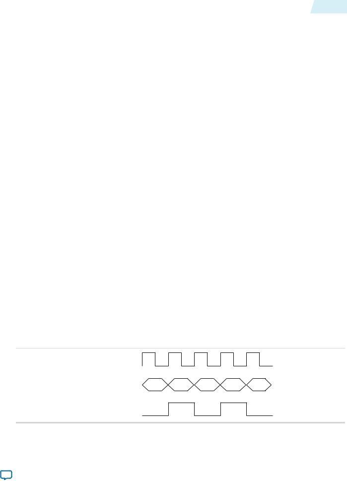
For the embedded synchronization format, the vid_datavalid signal indicates a valid BT656 or BT1120 sample. The CVI IP cores only read the vid_data signal when vid_datavalid is 1.
Figure 2-5: Vid_datavalid Timing
vid_data |
D0 |
D1 |
vid_datavalid
Interfaces |
Altera Corporation |
|
|
Send Feedback

2-6 |
Video Formats |
UG-VIPSUITE |
|
2015.01.23 |
|||
|
|
The CVI IP cores extract any ancillary packets from the Y channel during the vertical blanking. Ancillary packets are not extracted from the horizontal blanking.
•Clocked Video Input IP core—The extracted packets are produced through the CVI IP cores’ AvalonST output with a packet type of 13 (0xD).
•Clocked Video Input II IP core— The extracted packets are stored in a RAM in the IP core, which can be read via the control interface.
The extracted packets are produced through the CVI IP cores’ Avalon-ST output with a packet type of 13 (0xD).
For information about Avalon-ST Video ancillary data packets, refer to Ancillary Data Packets on page 2-19.
Separate Synchronization Format
The separate synchronization format uses separate signals to indicate the blanking, sync, and field information.
The CVO IP cores create horizontal and vertical syncs and field information through their own signals. The CVO IP cores create a sample for each clock cycle on the vid_data bus. The vid_datavalid signal indicates when the vid_data video output is in an active picture period of the frame.
Table 2-2: Clocked Video Input and Output Signals for Separate Synchronization Format Video
Signal Name |
|
Description |
|
|
|
vid_h_sync |
|
When 1, the video is in a horizontal synchronization period. |
|
|
|
vid_v_sync |
|
When 1, the video is in a vertical synchronization period. |
|
|
|
vid_f |
|
When 1, the video is interlaced and in field 1. When 0, the video is |
|
|
either progressive or interlaced and in field 0. |
vid_h |
|
When 1, the video is in a horizontal blanking period, (only for Clocked |
|
|
Video Output IP core). |
|
|
|
vid_v |
|
When 1, the video is in a vertical blanking period, (only for Clocked |
|
|
Video Output IP core). |
|
|
|
vid_de |
|
When asserted, the video is in an active picture period (not horizontal |
|
|
or vertical blanking). |
|
|
Note: Only for Clocked Video Input IP cores. |
|
|
|
vid_datavalid |
|
When asserted, the video is in an active picture period (not horizontal |
|
|
or vertical blanking). |
|
|
Note: Only for Clocked Video Output IP cores. |
|
|
|
Altera Corporation |
Interfaces |
|
|
Send Feedback