

Статьи на перевод PVDF_P(VDF-TrFE) / Enhanced dielectric response in P(VDF-TrFE) based all-organic nanocomposites
.pdfEnhanced Dielectric Response in P(VDF-TrFE) Based All-Organic
Nanocomposites
JINGWEN WANG, YE WANG, SHUQIN LI, JUN XIAO
Department of Material Science and Engineering, College of Material Science and Technology, Nanjing University of Aeronautics and Astronautics, Nanjing 210016, People’s Republic of China
Received 17 August 2009; revised 5 November 2009; accepted 11 November 2009
DOI: 10.1002/polb.21910
Published online in Wiley InterScience (www.interscience.wiley.com).
ABSTRACT: A nanocomposite with enhanced dielectric response is developed using poly(vinylidene fluoride-trifluoroethylene) [P(VDF-TrFE)] as matrix and Chemically modified high dielectric constant organic semiconductor—copper phthalocyanine oligomer (CuPc)—as filler. Transmission electron microscope (TEM)-observed morphologies reveal that in the nanocomposite the average size of CuPc particles is about 25 nm [1/24 of that of CuPc in physical blend of P(VDF-TrFE) and CuPc]. The hot-press nanocomposite film with 15 wt % CuPc can realize a dielectric constant of 540 at 100 Hz. The enhanced dielectric response in the nanocomposite demonstrates the significance of the interface effect in raising the material responses far beyond that expected by simple mixing rules when there is a
large dielectric contrast between the polymer matrix and the dielectric filler in the composite. It is also interesting to note that at high frequencies (such as 100 MHz) the nanocomposite has a dielectric constant of 100 and this value is comparable to those of current materials used in microwave applications. At 105 C that is near the ferroelectric-to-paraelectric phase transition temperature of the P(VDF-TrFE) ferroelectric, a much higher dielectric constant (about 1200 at 100 Hz) is obtained. VC 2010 Wiley Periodicals, Inc. J Polym Sci Part B: Polym Phys 48: 490–495, 2010
KEYWORDS: dielectric properties; electroactive polymers; interface effect; microstructure; nanocomposites
INTRODUCTION Because of their inherent advantages, such as high mechanical elasticity, high electrical breakdown strength, ease of processing in large areas, conformability to complicated shapes and surfaces, light weight, low cost and self-healing ability, and electroactive polymers (EAPs) with high electric energy density (U) are of major importance for a wide range of applications, such as energy-storage devices, actuators, sensors, artificial muscles, MEMS, and nonvolatile memories.1–9 For a linear dielectric material, the stored energy per unit volume is U ¼ [1/2]Ke0E2, where K is the relative dielectric constant, e0 is the vacuum dielectric permittivity ( ¼ 8.85 10 12 Fm 1), and E is the applied field. As a result, to achieve high stored electric energy density, it is necessary that either the material possesses a high dielectric constant or a high driving electric field can be applied to the material, or both. At the same time, generally speaking, the dielectric constant of most polymers are in a limited region ranging from 2 to 10, which is much less compared with their inorganic counterparts (such as ferroelectric ceramics).2,9 Consequently, for pure EAPs, to achieve high input electric energy density, which is required to generate high elastic energy density measuring both the stress and strain generation capability of an electromechanical material, a high electric field (usually more than 100 MV/m) is
Correspondence to: J. W. Wang (E-mail: wjw_msc@nuaa.edu.cn)
required to make up for the low dielectric constant.8,9 The high input electric field will lead to problems in some aspects (such as the external driving electric instruments), therefore, to reduce the applied electric field substantially in
such type EAPs, one has to raise the dielectric constant of this class of polymers substantially.2,9,10 To achieve this, in
the past two decades or so, various high dielectric constant or conducting fillers, either inorganic or organic, were selected as functional fillers to increase the dielectric constant of polymers.2,6–17 In general, the resultant composite with inorganic fillers usually more or less suffers from the loss of the flexibility and processibility, while for that with organic fillers, a high dielectric constant can be expected without increasing the composite modulus, as the modulus
of the organic fillers is comparable to that of the polymer matrix.8,9,16,17 Among organic fillers used, copper phthalocya-
nine oligomer (CuPc), an planar multiring organic semiconductor, exhibits a very high dielectric constant (> 105)
because of the electron delocalization within the giant conjugated molecule.2,15–20 Nevertheless, because molecular stack-
ing of CuPc macrocycles allows intermolecular interaction which results in large electrical conductivity, the oligomer suffers from high dielectric loss. In addition, it is brittle and difficult to process.20 As expected, when dispersed in
Journal of Polymer Science: Part B: Polymer Physics, Vol. 48, 490–495 (2010) VC 2010 Wiley Periodicals, Inc.
490 |
INTERSCIENCE.WILEY.COM/JOURNAL/JPOLB |

polymer matrix, polymer can provide an insulation layer around the CuPc particles to reduce the dielectric loss in the composite. However, the penalty here is that CuPc is usually not compatible with polymer matrix, thus susceptible to agglomeration to form large spherical particulates (>500 nm), which will lead to reduction of the breakdown field and
increase of the dielectric loss of the resulting composites.9,16,17 As a result, the size of filler particles of compo-
sites like polymer/CuPc should be substantially reduced to a proper level. It should be pointed out that, a significant aspect of such kind composite is the size effect of the CuPc particles when dispersed in polymer matrix, as the filler-
polymer interface plays an relatively important role on the enhancement of dielectric response of the composites.16,17,21
Recently, to improve the compatibility between CuPc and polymer matrix, thus reduce the size of CuPc particles in composite, we have grafted CuPc onto PVDF based copolymer/terpolymer backbone. Unfortunately, grafting CuPc to PVDF based polymers directly is very difficult, and the grafting ratio is low, as a result, the size of CuPc particles cannot be reduced to a satisfied level.16,17
Based on the above considerations, in this work, we have therefore developed a nanocomposite of poly(vinylidene fluoride-trifluoroethylene) [P(VDF-TrFE)] ferroelectric and chemically modified CuPc—CuPc grafted onto poly(p-chloro- methyl styrene) (PCMS) backbone (refer to the resulting product here as PCMS-g-CuPc)—in which the average diameter of CuPc particles is about 25 nm. P(VDF-TrFE) was chosen as polymer matrix in view of the fact that it is the most thoroughly studied polymeric ferroelectric and the first poly-
mer example with well-defined ferroelectric transition behavior.4,8,9,22,23 What’s more, it has a dielectric constant as high
as about 14, which is an important factor as for such composite a polymer matrix with higher dielectric constant is preferred. In addition, the dielectric constant of P(VDF-TrFE) can be further increased substantially when it is treated with high energy electron irradiation, thus converts the coherent polarization domain (all-trans chains) in normal ferroelectric P(VDFTrFE) into nanopolar regions, thus transforming the material into a relaxorlike system.8–10 For the filler of PCMS-g-CuPc in the nanocomposite, PCMS was selected to modify CuPc in respect that the grafting can remarkably improve the compatibility of CuPc and PCMS, consequently largely decrease the CuPc particle size within the PCMS-g-CuPc balls in the nanocomposite. In addition, the grafting procedure is very easy, and the grafting ratio of CuPc to PCMS is nearly 100%. For the nanocomposite of P(VDF-TrFE) and PCMS-g-CuPc [P(VDF-TrFE)/PCMS-g-CuPc] with tailored morphology, which was fabricated by combining solution-cast and hot-press techniques, a enhanced dielectric response can be expected. A further benefit is that, a much higher dielectric constant of the nanocomposite at the ferroelectric-to-paraelectric phase transition temperature (Curie temperature) of the P(VDF-TrFE) will be obtained, because the polymer matrix exhibits a maximum of dielectric constant at that point.24,25 Additionally, the major relaxation process of the nanocomposite was also discussed using the modified Cole-Cole equation.
ARTICLE
EXPERIMENTAL
Materials
P(VDF-TrFE) (68/32 mol %) with a weight average molecular weight of 200,000 was purchased from Solvay and Cie, Bruxelles, Belgium. PCMS (Mn ¼ 55,000) was purchased from Aldrich. The CuPc was synthesized following a procedure reported in ref. 26. PCMS-g-CuPc with 50 wt % CuPc was synthesized according to ref. 2. The grafting procedure was briefly depicted as follows. Triethylamine (3.0 mL) was added to a solution of PCMS (0.5 g) and CuPc (0.5 g) in Dimethylformamide (DMF) (40 mL). The solution was stirred at 65 C for 12 h under nitrogen atmosphere. After the Triethylamine and DMF were removed under reduced pressure, the mixture was washed with methylene dichloride to remove unreacted PCMS, if any, followed by distilled water to remove triethylamine hydrochloride. The final product was dried in vacuum. Other reagents were of analytical grade used as received.
Preparation of Films for Electric Measurement
A predetermined amount of PCMS-g-CuPc (or CuPc) was added to the solution of P(VDF-TrFE) in DMF, and then ultrasonically stirred for about 2 h to make the fillers dissolved thoroughly. Afterward, the solution was poured onto a clean glass slide and dried in air at 70 C for 5 h, then in vacuo at 50 C for 12 h to remove DMF residue. Finally, the film was annealed at 140 C under vacuum for 12 h and then slowly cooled to room temperature. The typical film thickness is40 lm. To improve the uniformity, the above film was then hot-pressed at 140 C under a pressure of 20 MPa. During the hot-press process, a four-layer stack of the solution-cast films was packed in a ‘‘sandwich’’ figuration.8 The films thus obtained were also annealed using the same method as mentioned above. The typical hot-press film thickness is 50 lm. For the electric characterization, the films were cut into small pieces of about 10 10 mm, and circular gold electrodes with a radius of 2.5 mm were sputtered in the center of both surfaces of the samples.
Characterization
The morphologies of the composites were characterized by transmission electron microscope (TEM) (Hitachi H-7650) and scanning electron microscope (SEM) (FEI Quanta200). For TEM observation, the specimen was prepared by placing a drop of a solution with about 1.0 wt % of composite in DMF on carbon film coated copper grid and then dried in air at 75 C before observation. To elucidate the microstructure inside the PCMS-g-CuPc in the nanocomposite, an ultramicrotomed sample of P(VDF-TrFE)/PCMS-g-CuPc (the sample thickness is about 50 nm) mounted on copper grid was particularly observed. Prior to SEM examination, the composite film samples were fractured in liquid nitrogen, and the cross sections of the specimens were sputter-coated with gold to avoid charge accumulation. The dielectric responses of the composite film samples were recorded using an Agilent 4194A impedance analyzer.
DIELECTRIC RESPONSE IN P(VDF-TrFE), WANG ET AL. |
491 |

JOURNAL OF POLYMER SCIENCE: PART B: POLYMER PHYSICS DOI 10.1002/POLB
FIGURE 1 TEM photographs of (a) P(VDF-TrFE)/CuPc and (b) P(VDF-TrFE)/PCMS-g-CuPc. Inset in (b) shows the TEM image of the ultramicrotomed sample of P(VDF-TrFE)/PCMS-g-CuPc.
RESULTS AND DISCUSSION
Morphology and Dielectric Properties of Solution-Cast Composites
The nanocomposite investigated here was composed of 70 wt % P(VDF-TrFE) and 30 wt % PCMS-g-CuPc (accordingly the content of CuPc in the nanocomposite is 15 wt %). For comparison purpose, the simple physical blend of P(VDFTrFE) and 15 wt % CuPc [P(VDF-TrFE)/CuPc] was also investigated.
Improvement of the dispersivity of CuPc in the P(VDF-TrFE)/ PCMS-g-CuPc nanocomposite in comparison with the P(VDFTrFE)/CuPc is much pronounced. Because of the incompatibility of CuPc (also PCMS) with P(VDF-TrFE), CuPc, and PCMS-g-CuPc aggregate in nearly spherical shape particles dispersed in P(VDF-TrFE) matrix (Fig. 1). The average size of PCMS-g-CuPc in P(VDF-TrFE)/PCMS-g-CuPc is about 80 nm, while the average CuPc particle size in P(VDF-TrFE)/CuPc is600 nm, because CuPc has a strong tendency to form stack
assemblies and microaggregates because of its planar shape and aromatic nature.9,16,17 To understand the dispersivity of
CuPc in PCMS-g-CuPc, TEM was used to observe the ultramicrotomed sample of P(VDF-TrFE)/PCMS-g-CuPc. From the inset in Figure 1(b), we can observe that within the PCMS-g- CuPc particles the CuPc inclusion with an average diameter of about 25 nm, about 24 times smaller than that of CuPc particulates in P(VDF-TrFE)/CuPc, was dispersed in the PCMS ‘‘matrix.’’ The origin of such a phenomenon here is that within the PCMS-g-CuPc, part of CuPc attached onto PCMS can acts as nucleation centers, which further induced the growth of CuPc crystallite. As the pendent CuPc oligomer groups were distributed separately along the PCMS backbone, the size of crystallite was restricted by the accessibility of adjacent CuPc molecules. On the contrary, aggregation of
CuPc can hardly be prevented in the simple physical blend of P(VDF-TrFE) and CuPc.2,16,17
Figure 2 shows the comparison of dielectric constant (K) of the solution-cast film samples of P(VDF-TrFE)/PCMS-g-CuPc, P(VDF-TrFE)/CuPc, and pure P(VDF-TrFE) as a function of
frequency from 100 Hz to 10 MHz at room temperature. As one can expect, compared with the pure P(VDF-TrFE) (K 14 at 100 Hz), the dielectric constant of the two composite samples is increased substantially, especially for the P(VDF- TrFE)/PCMS-g-CuPc. For example, the P(VDF-TrFE)/CuPc film sample has a dielectric constant of 75 at 100 Hz, meanwhile, at the same frequency, the dielectric constant of P(VDF-TrFE)/PCMS-g-CuPc reaches about 430, representing a more than 30 times increase compared with the pure P(VDF-TrFE). What’s more, the dielectric constant increases with decreasing frequency and the obvious dielectric dispersion was observed for both composite samples. It should be pointed out that, the dielectric constant of the composites is much higher than those derived from various models, especially for the P(VDF-TrFE)/PCMS-g-CuPc. For instance, if we regard the composites as random mixtures of P(VDF-TrFE) matrix and nearly spherical inclusions of CuPc and PCMS-g-
FIGURE 2 Dielectric constant collected at room temperature as a function of frequency from 100 Hz to 10 MHz for the solu- tion-cast film samples of P(VDF-TrFE)/PCMS-g-CuPc; P(VDFTrFE)/CuPc; and pure P(VDF-TrFE).
492 |
INTERSCIENCE.WILEY.COM/JOURNAL/JPOLB |
CuPc, respectively, according to the mean field-type composite theory,21,27 which is very reliable when the size effect is
not important, the effective dielectric constant of the composite can be estimated as:
K |
¼ |
2K1 þ K2 2c2ðK1 K2Þ |
K |
; |
(1) |
|
2K1 þ K2 þ c2ðK1 K2Þ 1 |
|
|
||
Where K1 and K2 are the dielectric constant of polymer matrix and dielectric filler, respectively, and c2 is the volume fraction of the filler. As K2 (4.3 105 to CuPc and 6.6 103 to PCMS-g-CuPc) is much larger than K1 ( 14), after simplification to the above equation, we finally obtain:
K |
¼ |
1 þ 2c2 |
K |
1 |
(2) |
|
1 c2 |
|
|||
It is estimated that K can only reach approximately 22 and 35 for P(VDF-TrFE)/CuPc and P(VDF-TrFE)/PCMS-g-CuPc, respectively. Obviously, this model cannot be used to explain the large enhancement of the dielectric constant as observed in both composites, especially for P(VDF-TrFE)/PCMS-g-CuPc.
The enhancement of dielectric constant of the composites could be arising from the interface exchange coupling effect,
as well as the Maxwell-Wagner-Sillars (MWS) space charge mechanism.16,28–30 For composites discussed here, the large
difference in dielectric constant between the polymer matrix and fillers will cause the MWS phenomenon, which results in low frequency dielectric dispersion as observed in Figure 2, especially for the P(VDF-TrFE)/PCMS-g-CuPc because of the large interface-to-volume ratios of CuPc particulates. More importantly, although the CuPc content in both composites is the same, the dielectric constant of P(VDF-TrFE)/PCMS-g- CuPc is more than 5.7 times higher than that of P(VDFTrFE)/CuPc, which leads to the conclusion that the exchange coupling effect may play a much important role in the
enhancement of dielectric constant of the nanocomposite due to the much smaller CuPc particle size.16,17,21
Morphology and Dielectric Properties of Hot-Press Nanocomposite
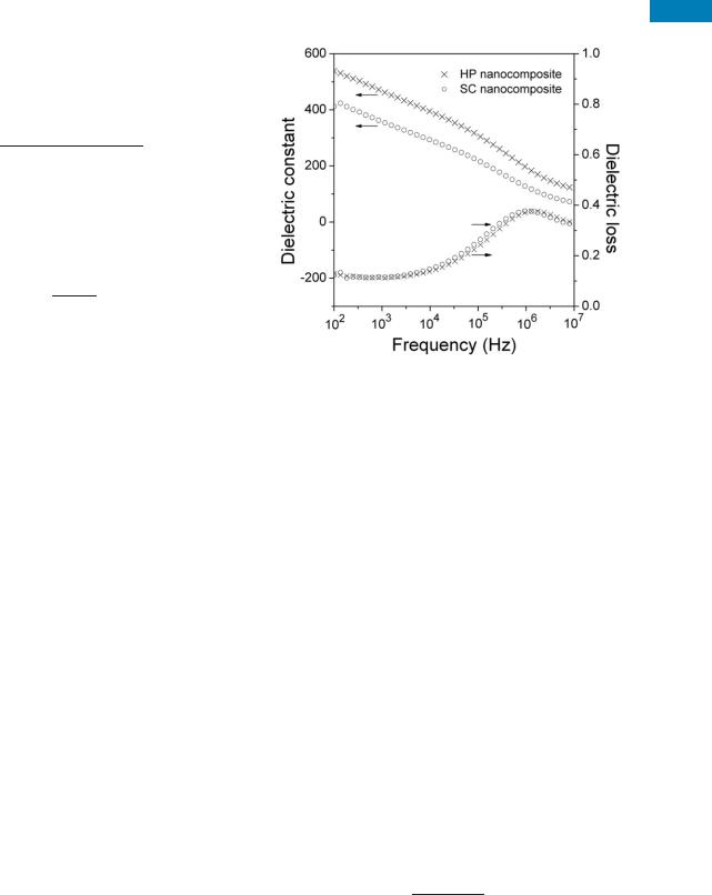
The further promoted dielectric response of P(VDF-TrFE)/ PCMS-g-CuPc nanocomposite can be achieved if film samples were prepared using hot-press method. As illustrated in Figure 3, compared with the solution-cast P(VDF-TrFE)/PCMS-g- CuPc film (SC nanocomposite), the hot-press P(VDF-TrFE)/ PCMS-g-CuPc sample (HP nanocomposite) exhibits a elevation of dielectric constant over the observed frequency range at room temperature. For example, the dielectric constant of the SC nanocomposite sample is about 430 at 100 Hz, while for the HP sample the dielectric constant at the same frequency reaches 540, representing a more than 25% increase in comparison to that of the SC nanocomposite. What’s more, even at high frequencies, the dielectric constants of the HP nanocomposite is still relatively high (e.g., 195 at 1 MHz and 150 at 10 MHz. Meanwhile, for the SC nanocomposite sample it is 125 at 1 MHz and 70 at 10 MHz). To make clear the
ARTICLE
FIGURE 3 Dielectric properties versus frequency from 100 Hz to 10 MHz at room temperature for the solution-cast film of P(VDF- TrFE)/PCMS-g-CuPc (SC nanocomposite) and the hot-press sample of P(VDF-TrFE)/PCMS-g-CuPc (HP nanocomposite).
possible origin of such phenomena here in respect of microstructure and morphology of the samples, SEM was used to observe the cross sections of the specimens. It was obviously found in Figure 4 that the uniformity of the SC nanocomposite film was poor as a polymer layer ( 6–8 lm in thickness) was observed, while for the HP nanocomposite sample the morphology is more uniform. The SC nanocomposite sample can be therefore considered as two parallel layers: one is a uniform composite layer and the other is a pure copolymer layer, which is a detrimental factor to the enhancement of dielectric constant of the whole composite.6 In addition, it is also observed from Figure 4 that, the SC nanocomposite with inclusion of the air bulbs has a less denser structure than the HP sample, which will also frustrate the enhancement of dielectric constant of the whole composite.6,10 Therefore, the higher dielectric constant observed in the HP nanocomposite sample compared with the SC nanocomposite is the consequence of the improvement in the homogeneity of the HP sample.
It is evident that the dielectric absorption of the composites with a maximum near 1 MHz is a simple relaxation process, as shown in Figure 5, which can be fitted quite well with the modified Cole-Cole equation:31
K ¼ K1 þ |
DK |
¼ K0 iK00; |
(3) |
1 þ ðixsÞ1 a |
where K1 is the dielectric constant at the high frequency limit, DK( ¼ Ks K1) is the dielectric relaxation strength, Ks is the static dielectric constant, s is the characteristic relaxation time, and a is the parameter describing the distribution of relaxation time. Fitting the data in Figure 5 using the above equation yields K1 ¼ 53, DK ¼ 265, a ¼ 0.45, and
DIELECTRIC RESPONSE IN P(VDF-TrFE), WANG ET AL. |
493 |

JOURNAL OF POLYMER SCIENCE: PART B: POLYMER PHYSICS DOI 10.1002/POLB
FIGURE 4 Cross-sectional SEM photographs of films of the SC nanocomposite (left) and the HP nanocomposite (right).
s ¼ 0.76 ls for the SC nanocomposite sample, and K1 ¼ 101.5, DK ¼ 309.5, a ¼ 0.48, and s ¼ 0.51 ls for the HP sample, which reveals that the HP nanocomposite has a dielectric constant more than 100 at 100 MHz and this value is comparable to those of current materials used in microwave applications. Moreover, the relaxation time obtained in the HP nanocomposite is much smaller than that obtained in the SC nanocomposite. The possible origin may attribute to more defects, such as air bulbs in the SC nanocomposite in comparison with the HP sample due to the different fabrication procedure, which will lead to the increase of the large part of the relaxation time spectrum of the SC nanocomposite. The difference of the relaxation times of the two nanocomposites indicates that the HP sample can exhibit a higher dielectric constant at a higher frequency than the SC nanocomposite, which is consistent with the fitting results above.
The temperature dependence of the dielectric behavior of the HP nanocomposite sample was also investigated and the results collected at several selected frequencies are illustrated in Figure 6. The data show that over a relatively broad temperature range, the dielectric constant of the HP nanocomposite is quite high, especially at lower frequencies. For example, a dielectric maximum of 1200 was observed at 100 Hz and about 105 C, which is the Curie temperature
of P(VDF-TrFE) copolymer.17 It is well known that for PVDF based ferroelectric polymers, the dielectric constant at the ferroelectric-to-paraelectric phase-transition temperature is much higher than that at room temperature.24 For the copolymer used here, the dielectric constant is about 50 at
the Curie temperature and 100 Hz, whereas it is only 14 at room temperature and the same frequency.17,32 Therefore,
the dielectric constant of the nanocomposite, which is determined by P(VDF-TrFE) and CuPc, also exhibits a dielectric maximum at the Curie temperature of P(VDF-TrFE) ferroelectric.25
CONCLUSIONS
In summary, a novel high dielectric constant nanocomposite comprised P(VDF-TrFE) and CuPc grafted onto PCMS was introduced. Film sample fabricated using hot-press method exhibits relatively better uniformity (consecutively improved dielectric properties) than that prepared using solution-cast method. The hot-press nanocomposite sample with just 15 wt % of CuPc exhibits a dielectric constant of 540 at 100 Hz and room temperature. Investigation using the modified ColeCole equation indicates that, even at 100 MHz, the dielectric constant of the nanocomposite can still be as high as 100. At
FIGURE 5 Cole-Cole plot of the dielectric behaviors at room temperature for the solution-cast P(VDF-TrFE)/PCMS-g-CuPc sample (SC nanocomposite) and the hot-press P(VDF-TrFE)/ PCMS-g-CuPc sample (HP nanocomposite). The dotted lines are the fitted results using the modified Cole-Cole equation.
FIGURE 6 Temperature dependence of dielectric constant of the HP nanocomposite sample at different frequencies: from top to bottom: 100 Hz; 1 kHz; 10 kHz; 100 kHz; 1 MHz; 10 MHz.
494 |
INTERSCIENCE.WILEY.COM/JOURNAL/JPOLB |

105 C, which is near the Curie temperature of P(VDF-TrFE) ferroelectric, a much higher dielectric constant ( 1200 at 100 Hz) is obtained. It is concluded that the dramatically enhanced dielectric response for the nanocomposite is mainly caused by the interface exchange coupling effect between nanosized CuPc particules and polymer matrix as well as the MWS space charge polarization mechanism.
The authors acknowledge the financial support provided by the Natural Science Foundation of Jiangsu Province (No. BK2009380) and the Aeronautical Science Foundation of China (No. 2006ZF52060). The authors thank Prof. Qun-Dong Shen of College of Chemistry and Chemical Engineering, Nanjing University for providing the P(VDF-TrFE) copolymer.
REFERENCES AND NOTES
1 O’Halloran, A.; O’Malley, F.; McHugh, P. J Appl Phys 2008, 104, 071101-1–071101-10.
2 Wang, J. W.; Wang, Y.; Wang, F.; Li, S. Q.; Xiao, J.; Shen, Q. D. Polymer 2009, 50, 679–684.
3 Bao, H. M.; Jia, C. L.; Wang, C. C.; Shen, Q. D.; Yang, C. Z.; Zhang, Q. M. Appl Phys Lett 2008, 92, 042903-1–042903-3.
4 Xu, H. S.; Shen, D.; Zhang, Q. M. Polymer 2007, 48, 2124–2129.
5 Zhang, J.; Zhu, D.; Matsuo, M. J Polym Sci Part B: Polym Phys 2009, 47, 1146–1155.
6 Arbatti, M.; Shan, X. B.; Cheng, Z. Y. Adv Mater 2007, 19, 1369–1372.
7 Wang, C. C.; Song, J. F.; Bao, H. M.; Shen, Q. D.; Yang, C. Z. Adv Funct Mater 2008, 18, 1299–1304.
8 Zhang, S. H.; Huang, C.; Klein, R. J.; Xia, F.; Zhang, Q. M.; Cheng, Z. Y. J Intell Mater Syst Struct 2007, 18, 133–145.
9 Zhang, Q. M.; Li, H. F.; Poh, M.; Xu, H. S.; Cheng, Z. Y.; Xia, F.; Huang, C. Nature (London) 2002, 419, 284–287.
10 Bai, Y.; Cheng, Z. Y.; Bharti, V.; Xu, H. S.; Zhang, Q. M. Appl Phys Lett 2000, 76, 3804–3806.
11 Dang, Z. M.; Zhou, T.; Yao, S. H.; Yuan, J. K.; Zha, J. W.; Song, H. T.; Li, J. Y.; Chen, Q.; Yang, W. T.; Bai, J. B. Adv Mater 2009, 21, 2077–2082.
ARTICLE
12 Dang, Z. M.; Lin, Y. Q.; Xu, H. P.; Shi, C. Y.; Li, S. T.; Bai, J. B. Adv Funct Mater 2008, 18, 1509–1517.
13 Wang, L.; Dang, Z. M. Appl Phys Lett 2005, 87, 042903-1–042903-3.
14 Shen, Y.; Lin, Y. H.; Li, M.; Nan, C. W. Adv Mater 2007, 19, 1418–1422.
15 Huang, C.; Zhang, Q. M. Adv Funct Mater 2004, 14, 501–506.
16 Wang, J. W.; Shen, Q. D.; Bao, H. M.; Yang, C. Z.; Zhang, Q. M. Macromolecules 2005, 38, 2247–2252.
17 Wang, J. W.; Shen, Q. D.; Yang, C. Z.; Zhang, Q. M. Macromolecules 2004, 37, 2294–2298.
18 Pohl, H. A. IEEE Trans Electr Insul 1986, EI-21, 683–692.
19 Nalwa, H. S.; Dalton, L.; Vasudevan, P. Eur Polym J 1985, 21, 943–947.
20 Venkatachalam, S. In Handbook of Organic Conductive Molecules and Polymers; Nalwa, H. S., Ed.; Wiley: New York, 1997; Vol. 2, Chapter 17, pp 747–755.
21 Li, J. Y. Phys Rev Lett 2003, 90, 217601-1–217601-4.
22 Lovinger, A. J. Science 1983, 220, 1115–1121.
23 Zhang, Q. M.; Bharti, V.; Zhao, X. Z. Science 1998, 280, 2101–2104.
24 Cheng, Z. Y.; Zhang, Q. M.; Bateman, F. B. J Appl Phys 2002, 92, 6749–6755.
25 Xu, H. S.; Bai, Y.; Bharti, V.; Cheng, Z. Y. J Appl Polym Sci 2001, 82, 70–75.
26 Achar, B. N.; Fohlen, G. G.; Parker, J. A. J Polym Sci: Polym Chem 1982, 20, 1785–1790.
27 Nemat-Nassera, S.; Li, J. Y. J App Phys 2000, 87, 3321–3331.
28 Seanoe, D. A. In Electrical Properties of Polymers; Academic Press: New York, 1982; Chapter 6, p 242.
29 Bobnar, V.; Levstik, A.; Huang, C.; Zhang, Q. M. Phys Rev Lett 2004, 92, 047604-1–047604-4.
30 Bobnar, V.; Levstik, A.; Huang, C.; Zhang, Q. M. Ferroelectrics 2006, 338, 107–116.
31 Cole, K. S.; Cole, R. H. J Chem Phys 1941, 9, 341–351.
32 Zhang, S. H.; Klein, R. J.; Ren, K. L.; Chu, B. J.; Zhang, X.; Runt, J.; Zhang, Q. M. J Mater Sci 2006, 41, 271–280.
DIELECTRIC RESPONSE IN P(VDF-TrFE), WANG ET AL. |
495 |