


206 Ship Design for Efficiency and Economy
Appendix
A.1 Stability regulations
Historical perspective: Rahola's criterion
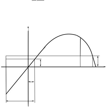
Rahola (1939) analysed statistically accidents caused by defects in stability and included the results in recommendations for `safe stability'. These recommendations are based on the criterion of a degree of dynamic stability up to 40° angle of heel. The dynamic stability can be represented by the area below the stability moment curve, i.e. as the integral of the stability moment over the range of inclination (Fig. A.1). (This quantity equals the mechanical work done, or energy used, in heeling the ship.) If the righting arm h is considered instead of the stability moment MSt, the area below the righting arm curve represents the dynamical lever e. This distance e is identical with the increase in the vertical distance between form and mass centres of gravity in heeled positions (Fig. A.2). e can be found by numerically evaluating the righting arm curve.
Rahola's investigation resulted in the standard requirements:
righting lever for 20° heel: |
h20° 0:14 m |
righting lever for 30° heel: |
h30° 0:20 m |
heel angle of maximum righting lever: |
max 35° |
range of stability: |
0 60° |
Other righting levers are seen as equivalent if
Z 40°
e D h d 0:08 m
0
for max 40°, where max is the upper limit of integration (Fig. A.3). Rahola's criterion disregards important characteristics (e.g. seakeeping
behaviour) and was derived for small cargo ships, especially coasters of a type which prevailed in the 1930s in the Baltic Sea. Nevertheless, Rahola's criterion became and still is widely popular with statutory bodies. The Germanischer
Appendix 207
Figure A.1 Dynamic stability energy E
Figure A.2 Lever of dynamical stability e D HB B0G cos
Figure A.3 Determining the dynamical lever e using Rahola

208 Ship Design for Efficiency and Economy
Lloyd confirmed the applicability of Rahola's criterion for standard postwar ships by analysing stability accidents which occurred after World War II (Seefisch, 1965).
While it was never made directly a stability regulation, Rahola's criterion has influenced most stability regulations for cargo ships and trawlers intended to guarantee a minimum safety against capsizing.
International regulations
Various stability requirements of the past have been consolidated into a few international codes on stability which apply for virtually all cargo ships:
The Code on Intact Stability (IMO regulation A.749(18))
SOLAS (1974) concerning damage stability
In addition, Rule 25 of MARPOL 73/78 affects damaged stability of tankers. This book reflects the state of the regulations in 1997. Modifications and additions are actively discussed. Stability regulations will thus undoubtedly change over time.
Code on Intact Stability
The Code on Intact Stability, IMO Resolution A.749(18), consolidates several previous stability regulations (IMO, 1995). The code contains regulations concerning all cargo ships exceeding 24 m in length with additional special rules for:
cargo ships carrying timber deck cargo
cargo ships carrying grain in bulk
containerships
passenger ships
fishing vessels
special purpose ships
offshore supply vessels
mobile offshore drilling units
pontoons
dynamically supported craft
The main design criteria of the code are:
General intact stability criteria for all ships: |
|
|||
1. |
e0;30°° |
0:055 m rad; e0;30° is the area under |
the static stability curve |
|
|
to 30 |
|
0:09 m rad; corresponding area up to 40° |
|
|
e0;40° |
|||
|
e30;40° |
0:03 m rad; corresponding area between 30° and 40°. |
||
|
If the angle of flooding f is less than 40°, f instead of 40° is to be |
|||
|
used in the above rules. |
|
||
2. |
h30° 0:20 m; h30° is the righting lever at 30° |
heel. |
||
3.The maximum righting lever must be at an angle 25°.
4.The initial metacentric height GM0 0:15 m.
In addition, IMO requires for passenger ships:
1. The heel angle on account of crowding of passengers to one side should
not exceed 10°. A standard weight of 75 kg per passenger and four passengers/m2 are assumed.
Appendix 209
2.The heel angle on account of turning should not exceed 10°. The heeling moment is
|
V2 |
|
|
|
T |
|
MKr D 0:02 |
0 |
1 KG |
|
|
||
L |
2 |
|||||
Severe wind and rolling criterion (weather criterion):
The weather criterion is intended to reflect the ability of the ship to withstand the combined effects of beam wind and rolling (Fig. A.4). The weather criterion requires that area b a. The angles in Fig. A.4 are defined as
follows:
0 angle of heel under action of steady wind; 16° or 80% of the angle of deck immersion, whichever is less, are suggested as maximum.
1 angle of roll windward due to wave action2 minimum of f, 50°, c
f is the heel angle at which openings in the hull, superstructures or deckhouses, which cannot be closed weathertight, immerse.
c angle of second intercept between wind heeling lever lw2 and righting arm curve.
The wind heeling levers are constant at all heel angles:
kg A Z lw1 D 0:051376 m2 1
lw2 D 1:5 lw1
Ais the projected lateral area of the portion of the ship and deck cargo above the waterline in [m2].
|
,,, |
|
|
|
b |
|
|
Lever |
, |
|
|
,,,,,, |
|
|
Lw1 |
φ2
Angle of heel
a
φ0
GZ
Lw2
φC
φ1
Figure A.4 Weather criterion
210 Ship Design for Efficiency and Economy
Z is the vertical distance from the centre of A to the centre of the underwater lateral area or approximately to a point at T=2 in [m].
1 is the displacement in [t].
The angle 1 [deg.] is calculated as
p
1 D 109 k X1 X2 rs
kfactor as follows:
k D 1:0 for a round-bilged ship having no bilge or bar keels k D 0:7 for a ship having sharp bilges
k according to Table A.1 for a ship having bilge keels, a bar keel or both. Ak is the total overall area of bilge keels, or area of the lateral
projection of the bar keel, or sum of these areas [m2]. X1 factor as shown in Table A.2.
Table A.1 Factor k
.Ak 100/=.L B/ |
0 |
1.0 |
1.5 |
|
2.0 |
2.5 |
|
3.0 |
|
3.5 |
4.0 |
||||||
|
|
k |
|
1.0 |
0.98 |
0.95 |
0.88 |
0.79 |
|
0.74 |
|
0.72 |
0.70 |
||||
Table A.2 Factor X1 |
|
|
|
|
|
|
|
|
|
|
|
|
|||||
|
|
|
|
|
|
|
|
|
|
|
|
|
|
|
|
|
|
B=T |
2.4 |
2.5 |
2.6 |
2.7 |
2.8 |
|
2.9 |
3.0 |
3.1 |
3.2 |
3.4 |
3.5 |
|||||
X1 |
|
1.0 |
|
|
0.98 |
0.96 |
0.95 |
0.93 |
0.91 |
0.90 |
0.88 |
0.86 |
0.82 |
0.80 |
|||
Table A.3 Factor X2 |
|
|
|
|
|
|
|
|
|
|
|
|
|||||
|
|
|
|
|
|
|
|
|
|
|
|
|
|
|
|
|
|
CB |
|
0.45 |
|
0.50 |
0.55 |
|
|
|
0.60 |
0.65 |
|
0.70 |
|
|
|||
X2 |
|
0.75 |
|
|
0.82 |
0.89 |
|
|
|
0.95 |
0.97 |
|
1.0 |
|
|
|
|
r D 0:73 0:6 |
|
|
|
|
|
|
|
|
|
|
|
|
|
|
|||
OG=T. |
|
|
|
|
|
|
|
|
|
|
|
|
|||||
|
OG |
is the distance between the centre of gravity and the waterline [m] (C if the centre of gravity |
|
|
|||||||||||||
|
is above the waterline, if it is below). |
|
|
|
|
|
|
|
|
|
|
||||||
s |
factor as shown in Table A.4. |
|
p |
|
|
|
|
|
|
|
|
|
|||||
|
The rolling period Tr is given by Tr D 2 C B= |
|
; C D 0:373 C 0:023.B=T/ 0:00043 L. |
|
|
||||||||||||
|
|
GM |
|
|
|||||||||||||
X2 factor as shown in Table A.3.
rD 0:73 0:6OG=T
OG is the distance between the centre of gravity and the waterline [m]
|
(C if the centre of gravity is above the waterline, if it is below). |
||||||||
s |
factor as shown in Table A.4 |
|
p |
|
|
|
|||
|
|
|
|
|
|
|
|
|
|
|
The rolling period Tr is given by Tr D 2 C B= |
GM |
; C D 0:373 C |
||||||
|
0:023.B=T/ 0:00043 L. |
|
|
|
|
|
|
||
Intermediate values in Tables A.1 to A.4 should be linearly interpolated. |
|||||||||
Table A.4 Factor s |
|
|
|
|
|
|
|
|
|
|
|
|
|
|
|
|
|
|
|
Tr |
6 |
7 |
8 |
12 |
14 |
16 |
18 |
20 |
|
s |
0.100 |
0.098 |
0.093 |
0.065 |
0.053 |
0.044 |
0.038 |
0.035 |
|
Appendix 211
For ships operating in areas where ice accretion is likely, icing allowances should be included in the stability calculations. This concerns particularly cargo ships carrying timber deck cargoes, fishing vessels and dynamically supported crafts.
SOLAS (1974)
The damaged stability characteristics of ships are largely defined in the SOLAS Convention (Safety of Life at Sea) (IMO, 1997). Damaged stability is required for nearly all seagoing ships, either on a deterministic or probabilistic basis. The probabilistic approach requires a subdivision index `A' to be greater than a required minimum value `R'. `A' is the total probability of the ship surviving all damages. A D 6pi si, where pi is the probability that a certain combination of subdivisions is damaged and si is the survivability factor ranging from 0 (no survival) to 1 (survival). In 99% of all damage cases of actual designs, s is either 1 or 0 (Bjorkman,¨ 1995). Sonnenschein and Yang (1993) point out some weaknesses in the SOLAS rules in comparison to U.S. Coast Guard rules. Further discussions of the SOLAS rules, sometimes with examples, are found in Abicht (1988, 1989, 1992) and Gilbert and Card (1990). All ships transporting bulk grain are subject to regulations as documented in Chapter VI of SOLAS (1974), amended in 1994.
MARPOL 73/78
Rule 25 of the MARPOL convention (IMO, 1992) imposes special requirements concerning damage stability for tankers. These requirements are, like some of the SOLAS requirements, probabilistic, but differ in detail; e.g. MARPOL assumes that damage location is as probable everywhere along the ship's length, while SOLAS assumes that damage is more likely in the foreship (Bjorkman,¨ 1995).
National regulations (Germany)
National regulations usually follow the above international regulations, but may impose additional requirements. German rules are given here as an example.
SBG regulations
In 1984 the SBG (Seeberufsgenossenschaft D German Mariners' Association) issued new regulations for intact stability which consider ship type and cargo type (SBG, 1984). These recommendations refer to the righting arm curve. Table A.5 gives the minimum required values.
Ships with L 100 m and 50° < ° 0 < 60°: h30° D 0:2 C .60° 0/ 0:01. |
|||||||
Cargo-carrying pontoons: 0 30 ; e0; max 0:07 m rad. |
|
||||||
Containers as deck cargo: |
GM |
0 0:30 m for L 100 m, |
GM |
0 |
0:40 m for |
||
L > 120 m, linear interpolation in between. |
|
||||||
Timber as deck cargo, densely stowed: |
|
0 0:15 m; h30° |
0:10 m for |
||||
GM |
|||||||
F0=B 0:1, h30° 0:20 m for F0=B 0:2, linear interpolation in between. F0 is an ideal freeboard, the difference between ideal draught and available
mean draught.
212 Ship Design for Efficiency and Economy
Table A.5 Stability requirements of the SBG for cargo ships (summary)
|
|
|
h30° |
|
0 |
|
e0;30° |
e30;40° |
e0;40° |
0 |
|
|
|
|
GM |
||||||||
|
|
|
[m] |
[m] |
[m rad] |
[m rad] |
[m rad] |
[deg] |
|||
General, L 100 m |
0.20 |
0.15 |
0.055 |
0.03 |
0.09 |
50±60 |
|||||
General, 100 m < L < 200 m |
0.002L |
0.15 |
0.055 |
0.03 |
0.09 |
50±60 |
|||||
General, L > 200 m |
0.40 |
0.15 |
0.055 |
0.03 |
0.09 |
50±60 |
|||||
Tugs |
|
0.30 |
0.60 |
0.055 |
0.03 |
0.09 |
60 |
||||
|
|
|
|
|
|
|
|
|
|
|
|
h30° |
Righting lever at 30° heel |
|
|
|
|
|
|
|
|
|
|
GM |
0 |
Metacentric height corrected for free surfaces |
|
|
|
|
|
|
|
|
|
e0;30° |
Area under static stability curve to 30° |
|
|
|
|
|
|
|
|
||
e30;40° |
Area under static stability curve between 30° and 40° |
|
|
|
|
|
|
||||
e0;40° |
Area under static stability curve to 40° |
|
|
|
|
|
|
|
|
||
0 |
Stability range; heeling angle at which righting lever becomes zero again |
|
|
||||||||
Timber as deck cargo, packaged timber: |
|
0 |
0:15 m; h30° 0:15 m. |
||||||||
GM |
|||||||||||
Coke as deck cargo: h30° |
is to be increased by 0.05 m. |
|
|
||||||||
Passenger ships:
Maximum heel angles are:
10° resulting from passengers crowding to one side
12° resulting from passengers crowding to one side and turning
12° resulting from lateral wind pressure.
The minimum residual freeboard to the bulkhead deck or openable windows must be 0.20 m when the ship is heeled by the above moments. Ships of over 12 m width must show that the lower edges of the windows above the bulkhead deck are not submerged under dynamic wind conditions.
The heeling moment due to passengers crowding on one side assumes 4 persons/m2 for open spaces, otherwise the `most realistic' assumptions, and 750 N per person plus 250 N luggage (50 N for day trips), centre of gravity 1 m above the deck at the side at L=2.
The heeling moment due to turning is as given for the IMO code of intact stability above.
Ships with large wind lateral area, except passenger ships: The heel angle under side wind is to be calculated.
T
MKr D p A lw C
2
p D 0:3 kN/m2 for coastal operation (Bft 9)
p D 0:6 kN/m2 for short-distance operation (Bft 10)
p D 1:0 kN/m2 for middleand long-distance operation (Bft 12)
The heel angle may not exceed 18°. The minimum residual freeboard under heel is 10% of the freeboard for the upright ship.
Further regulations concern tankers, hopper dredgers, ships with self-bailing cockpit or without hatch covers, offshore supply vessels, and heavy cargohandling.
German Navy stability review
All ships (except submarines) in the German navy are subject to a `stability review' in which the lever arm curves of righting and heeling moments are compared for smooth water conditions and in heavy seas (Vogt, 1988). The