

Safety in the use of RF heaters and sealers
Some hardware stores sell thin, perforated, aluminium sheet metal, with a pattern resembling a cane-bottomed chair that has proved very satisfactory for ports (figure A-6). For example, patterns with 3-mm diameter holes on 6-mm centres, or 6-mm holes on 9-mm centres, provide good shielding. At 30 MHz, a sheet with 15-mm square holes on 25-mm centres is not as effective a shield as other patterns mentioned, probably because of the large holes.
Woven wire screen, even if made of aluminium or bronze, is not a preferred shielding material for dielectric heaters. Apparently, only occasional and poor electrical contact occurs between wires in the screen as they cross each other. Currents that must flow diagonally across the woven screen must pass over many joints with low electrical conductivity. Thus a single layer of perforated aluminium is a more effective shield than two layers of bronze screen isolated from each other to provide a double shield.
To reduce reflection from room lighting and improve viewing, the outer surface can be painted flat black. If a window is desired for viewing the interior of the shield, the outer surface of the perforated metal can be painted flat black, being careful to avoid painting surfaces where contact must be made. Illumination within the cabinet will also be helpful for viewers. Often sufficient RF fields exist within the cabinet to light a fluorescent lamp tube without its being connected to the AC power line.
Doors and removable panels
Access to the shield interior is required for insertion and removal of the material to be heated, as well as for servicing and cleaning the shield. Doors and removable panels to accommodate servicing and cleaning must be opened and shut frequently. Good electrical conductivity must be present around the contact edges (disconnect joints) between the doors and panels and the associated frames whenever the RF is turned on. It is imperative that good current paths (i.e. high electrical conductivity) be restored when the door is closed or the removable panel is repositioned against its frame. To assure high electrical conductivity at the disconnect joints, springy material is installed around the contact edges of the door. A convenient material is metallic "weather stripping" that is usually made of a springy bronze material (e.g. beryllium copper). If the door frame or the door is slightly warped or curved, the weather stripping should be serrated at frequent intervals to assure good contact. The serrations are usually made by cutting the material perpendicular to the edge, but only part way through, making finger-like contacts that can follow wavy surfaces and yet provide frequent contacts. Often it is best to use a thin, fine-toothed saw blade to cut a narrow slot in the "weather stripping". The design shown in figure A-5, although it may be more expensive at first, requires less maintenance and will last longer than the design in figure A-7.
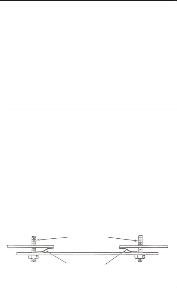
Figure A-7. Contact strips between removable panel and fixed part of the cabinet
Securing bolts
Springy metal contacts
44
Appendix A
One disconnect joint method uses contact strips between the removable panel and the fixed part of the cabinet frame (figure A-7). This method is often used when the panel or door is infrequently removed (e.g. monthly, quarterly, or yearly). The number of screws needed to mount the panel or door has to be sufficient to hold it closed against the force of the contact strips. Care must be exercised when the panel is removed to ensure that the contacts are not deformed. To prevent unbalanced pressure on the contacts and deformation of the panel, all of the screws must be used, and they must be tight.
A second method of using the "weather stripping" for a large, sliding door which is open frequently is illustrated in figure A-8. The force required to make good electrical contact is provided by the frame within the door and the mating frame around the door opening. Because the door is opened and closed many times a day, using shielding methods that require many manual fasteners, such as bolts or screws, is not practical. Only one or two quick disconnect fasteners (e.g. a latch or clamp) are normally used to make sure the door remains closed.
The contacts increase the force required to close (and sometimes open) the door, particularly if the door is large. A contact force of 60 newtons per metre of door perimeter linear centimetre is typical. For a door 2 m high by 1 m wide (a perimeter of 6 m) with a coefficient of friction of 0.2, the force needed is 72 newtons. A value of 0.2 is probably high because it presumes all the contacts are compressed and released at the same instant. This does not usually happen. Hinged doors, with "weather stripping" on their contact edges will not require as much force either. Of course, smaller doors or panels require less force.
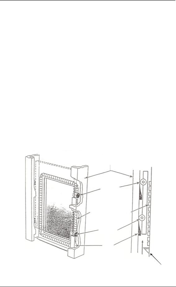
Figure A-8. Contact strips for frequently used sliding door
Door partially open
Metal frame (attached to shield cabinet)
Roller
Uncompressed metal spring contacts (attached to shield cabinet)
Roller
Cam
Shield cabinet
45
Safety in the use of RF heaters and sealers
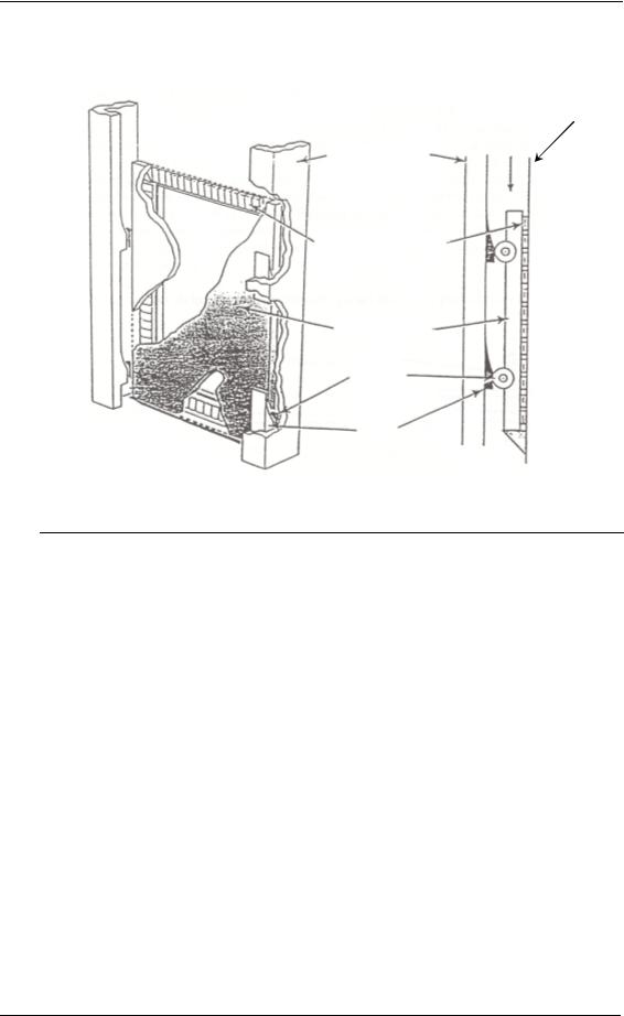
Door closed
Shield cabinet
Metal frame (attached to shield cabinet)
Compressed metal spring contacts
Metal door
Roller
Cam
Vestibules (shielding tunnels)
Previously, the design of ports and doors was discussed in some detail. The size and placement of slots in the shield were shown to be critical with regard to leakage of radiation. Slots that are parallel to current paths and have a narrow width will minimize operator exposure. An extension of this slot principle is illustrated by equipment that uses conveyor belts to move dielectric material into and out of the RF field for processing. Usually the shield opening cannot be a slot at all, but it is a rectangle with a height and width that do not greatly differ. However, a shield opening with approximately equal height and width will have larger RF energy leakage than a narrow slot parallel to current paths. Consequently, other methods are needed to reduce RF leakage from shield openings with approximately equal height and width. The vestibule method can often be used to do this. A vestibule is a metal tunnel that the dielectric material to be heated traverses while it passes into and out of the RF field. One end of the tunnel encloses the shield opening (slot) and the other end allows insertion and removal of the dielectric material. For reasons discussed below, a vestibule which is properly designed can greatly reduce RF leakage, and its use is illustrated in figure A-9. Current flow in a shield cabinet is contrasted in figure A-9 (vestibule) and figure A-10 (no vestibule). Vestibules are also useful in reducing the energy that escapes from a large ventilation duct.
46
Appendix A
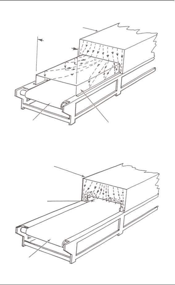
Figure A-9. Current flow in a shield opening with a vestibule
Main shield cabinet
Vestibule width
Conveyor belt (non-metallic)
Vestibule
(added to shield cabinet)
Figure A-10. Current flow in a shield opening without a vestibule
Shield cabinet
Slot opening
Conveyor belt (non-metallic)
47
Safety in the use of RF heaters and sealers
For very thin materials used in dielectric heating applications, a slot may be used for the entrance and exit of materials. However, these slots are wide and are perpendicular to the current paths.
Alternatively, a "short vestibule" can be used. A short vestibule can be formed by having its top and bottom very close; to be effective, it must be of sufficient length to act as a capacitor through which the normal shield currents can flow across the slot (figure A-11).
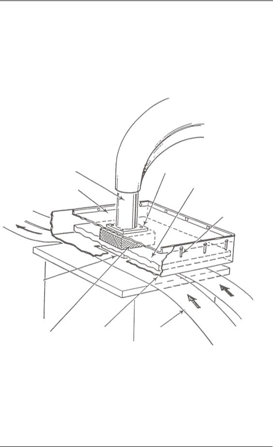
Figure A-11. Principle of a "short vestibule"
Press flange
Piston (to raise or
lower top press plate) Piston mounting flange
Top press plate
Aluminium top tray ("cookie sheet")
Slots (to move shield up or down)
Die piece
Dielectric |
Capacitively |
Dielectric material |
coupled shield |
||
insulator |
(with right-angle bend) |
|
Alternating currents flow into and out of this capacitor and the higher the frequency the greater the current. These currents can be large even though the capacitance is small (see Appendix B). Conversely, the greater the capacitance, the lower the voltage needed to drive a given current through it. This is illustrated by the capacitance vestibule of figure A-11 described above, where the top and bottom are close. The dielectric material to be heated increases the capacitance between the press plates forming the short vestibule. Because the
48
Appendix A
currents can pass through the shield without an appreciable voltage across the capacitor (press plates), the energy radiated through the opening where the material passes will be minimized.
Sometimes the upper plate of the capacitor (short vestibule) is too close to allow the material to pass through it easily. However, once the material is loaded, the upper plate can be lowered to the desired position before the RF energy is applied. Then the upper plate can be raised when the press opens or when new material is loaded. The upper capacitor plate is moved by an independent power source. The upper plate must be lowered to ensure proper shielding whenever the RF energy is on.
This type of short vestibule was tested in the laboratory for engineering modelling purposes. The opening was 3 mm high and the re-entrance port was 25 cm long. A 12.5-cm long vestibule was also tested but then the leakage exceeded recommended levels. This type of shield would be very practical for operations that seal large areas of material such as truck covers or tents.
For thicker materials, where the capacitance of this short vestibule is not sufficient to keep the voltage low across the capacitor, other means must be used. A tunnel-like vestibule can be used to reduce the amount of energy escaping (figure A-9). If properly constructed, it can reduce emissions to recommended levels. Tunnel vestibules are often used for heaters with conveyor belts.
The width and height of a vestibule should be kept to a minimum. The size limitation plays a role in harmonic emissions. Harmonics which are multiples of the operating frequency, sometimes extend to multiples of 20 and above. At high frequencies, a vestibule can pass emissions of RF energy unattenuated (see Appendix C). The narrower the vestibule, the fewer harmonics will be able to pass.
The length of a vestibule required to reduce RF leakage to levels at or below recommended levels is difficult to determine. Although a number of factors influence the length needed, experience has shown that the RF field's orientation to the vestibule is very important. This information can be determined with the help of the manufacturer or dielectric heating consultant. If the RF electric field in the enclosure is at right angles to the height of the vestibule, more energy will be coupled into the vestibule than if the electric field is parallel to the vestibule's length. Vestibules should be about twice as long when their width is at right angles to the field as when their length is parallel to it. Where the field is across the vestibule (i.e. parallel to width), and it is high, the length is often twice the width.
The orientation and distribution of the electric field changes along the length of the vestibule. Some vestibules, which have been constructed with the length and width equal for similar field configurations, have been successful. With equal length and width, electric field attenuation towards the end of the vestibule has approached 50 dB if the cut-off frequency (see Appendix C) is much higher (i.e. about 300 times higher) than the frequency being considered. However, the voltage difference induced on the vestibule by the RF field is not known, nor is the exact attenuation which depends on the vestibule length.
Electrical safety is another important factor in determining the minimum length. The vestibule should be long enough to prevent an operator from reaching into the vestibule and touching the high voltage electrode(s). Safety considerations alone dictate that vestibules be at least 75 cm.
Attenuation panels attached to the inside of vestibules are needed if the harmonics of the generator's fundamental frequency are above the cut-off frequency of the vestibule, as is often the case. A lossy material that readily absorbs RF radiation may have to be included in the vestibule to reduce the RF leakage to desired levels.
49