


Safety in the use of RF heaters and sealers
added to improve electrical contact between fasteners. Often RF leakage can be reduced by improving contact between shield sections, by adding contacts, or by lengthening vestibules (see figure A-11).
Another form of exposure control in widespread use by RF sealer users is screenroom enclosures. A metal screen-encased room, is used to house (usually older model) RF sealers as well as the operators. This constitutes effective radiation control for the rest of the plant. However, the operators of these screened units may receive a higher dose of RF energy than they would had there been no-screen room (Gandhi et al., 1977; Appendix D).
Just as the screen room may enhance exposure to operators, improper shielding by untrained or uninformed individuals may create more serious exposure problems. Portions of a formerly well-shielded machine could also be rendered ineffective and cause more radiation by simple misuse or partial removal of the shield. In order to determine the effectiveness of the shield, it is essential that both the electric and the magnetic fields and induced current be measured (Murray et al., 1992). In a shielding evaluation experiment, Ruggera and Schaubert (1982) have shown that some attempts at shielding may reduce the electric field strength to quite a low level, but the corresponding magnetic field strength can be increased or vice versa.
8.3.2. Installation details
8.3.2.1. Installations near pipes
Excessive radiation in unexpected locations in a plant can occur when RF energy leaking from a dielectric heater couples to a nearby pipe. The pipe or other metal object can act as a good antenna for high frequencies. If the pipe is the right length (e.g. equal to an integral multiple of quarter wavelengths), it will resonate (couple maximum RF energy) at the fundamental operating frequency or at one of its harmonics.
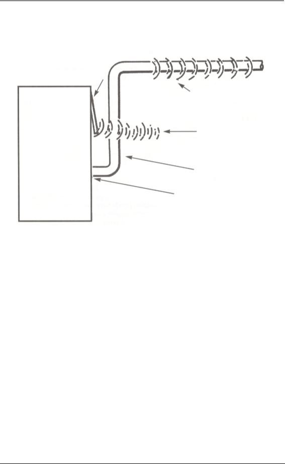
Figure 5 illustrates how RF energy couples to pipes and how it can be radiated at other locations as it follows the pipe. The best solution, after shielding the generator cabinet as well as possible, is to move the pipes away from the RF generating equipment, especially away from potential openings in the cabinet shielding. Radiation can leak from joints in panels, output lead locations and ventilation openings. Where possible, any pipes carrying power to the heater should be located underground and brought up through the floor directly into the bottom of the heater. This minimizes RF leakage into the work area. Generator pipes that are perpendicular to the cabinet surface are best, because they leave the equipment as directly as possible and thus minimize the amount of pipe to which RF energy can couple.
26
Control technology and radiation protection programme
Figure 5. RF energy coupling to pipes
|
Loose panel |
|
RF energy |
|
radiates from pipe |
RF |
RF emission |
generator |
from loose panel |
cabinet |
|
|
Nearby metal pipe |
|
Need good electrical contact |
|
between shield cabinet |
|
and metal pipe |
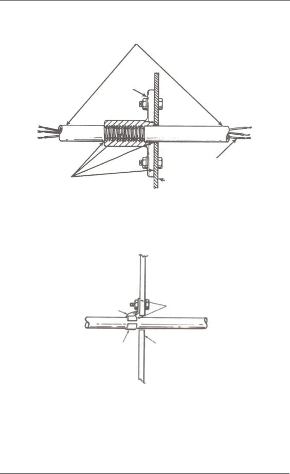
Power lines, water lines, and aircooling ducts connected to the generator may also have RF energy coupled to them. Figure 6 illustrates a method that successfully prevents the coupling of RF radiation to pipes. A pipe flange that threads onto the outside of the pipe and is bolted to the unpainted surface of the cabinet gives the best electrical contact. This construction will keep all cabinet currents inside the shield since currents will not flow very far down the inside of the pipe unless the pipe's diameter is one-half the RF wavelength or greater. For example, currents above 1,475 MHz would flow down a 10-cm (4-inch) diameter pipe. For currents to flow down smaller pipes, the RF frequency must be even higher (wavelength even smaller). The current flow will occur in a pipe only when the cut-off frequency is exceeded (see Appendix A on vestibules).
If the use of a pipe flange is not desirable, a clamp can be installed around the pipe and connected to the cabinet (figure 7). This connection should be as short and wide as possible. Also, the hole in the metal shield through which the pipe enters should be as small in diameter as is practical. This avoids large slot-type openings where RF energy may escape.
27
Safety in the use of RF heaters and sealers
Figure 6. Method to prevent the coupling of RF radiation to pipes
Metal pipe (enclosing electrical wires)
Avoid paint, dirt, rust or corrosion at these joints
60 Hz electrical wires
RF generator cabinet shield
Figure 7. Clamp installed around pipe and connected to the cabinet to inhibit current
Short wire strap |
Avoid paint, dirt, rust or |
|
corrosion at these joints |
||
bolted to shield and clamp |
||
|
Pipe clamp |
Metal shield |
|
Non-metallic pipes should be used wherever possible because they cannot pick up RF energy and reradiate it. However, any electrical wiring connected to RF heaters must be enclosed in metallic pipes or conduits. This is necessary because these wires will carry unwanted RF energy away from the heater. Using metallic pipes to enclose these RF-carrying wires is the only way to keep the RF energy on them from being radiated. In extreme cases, where sensitive instrumentation is employed, it may be
28
Control technology and radiation protection programme
necessary to include an RF filtering device in series with each wire leading from the RF heater to the instrument. Often it is sufficient to install a large (e.g. 0.005 microfarad) capacitor with the shortest possible leads between each wire and ground. Where high field intensities are present, a special RF filter, including several capacitors and an inductor, may be required to prevent interference with very sensitive instruments. The capacitors should be rated for at least 100 volts.
Many RF power output cables on dielectric heaters are high current conductors, and generally cannot be installed without at least one slot or opening in the generator cabinet. To assure proper shielding and meet RF safety requirements, the output cable must be inside a metal conduit of high conductivity (figure 8). In lower power RF heater installations, aluminum downspout pipe has been used successfully.
Figure 8. Square copper duct
This end connects to RF generator cabinet
RF generator cabinet |
Duct shield (completely enclosing |
|
high voltage output lead of heater) |
||
|
||
All bolts are |
|
|
on 3-inch centre |
|
High voltage
output lead This end of lead connects to RF
dielectric heating applicator
In large, higher power RF heaters, the output pipe may be 30 to 45 cm (12 to 18 inches) in diameter and made of heavy aluminum for rigidity. The inner surface of this pipe is used to carry the ground currents from the applicator back to the generator. Forward currents from the generator to the applicator are usually carried on another conductor that is coaxial to the outer one. Usually, copper water pipe is used, although specially fabricated aluminum tubing may be used in larger equipment. Aluminum irrigation tubing also is often used.
In very small heaters with low RF power, a standard, commercially available, RF coaxial cable (e.g. RG-9) is sometimes used. The cable must carry considerably more current in this situation than it does for normal communications services. Thus, except for very low-power generators, using commercially available coaxial line with insulation made of polyethylene or similar material is usually not practical. The
29