

Rivero L.Encyclopedia of database technologies and applications.2006
.pdfmechanism so that any communication of data between back-end application systems is reliable. This ensures that no communication is lost. This is often achieved by sending messages through persistent and transactional queuing systems (Gray & Reuter, 1993). Queuing systems store messages persistently and transactionally, achieving an exactly-once message communication.
EAI technology uses adapters (J2EE Connector Architecture, 2004) in order to connect to the proprietary interfaces of back-end application systems. An adapter knows the proprietary interface and provides a structured interface to the EAI technology. This allows EAI technology to connect to any back-end application system for which an adapter is available. If no adapter is available for a particular back-end application system, then a new one has to be built. Some EAI technologies provide an adapter development environment allowing new adapters to be constructed. Adapters can retrieve data from back-end application systems as well as store data within back-end application systems. They therefore enable the communication of the EAI technology with the back-end application systems.
EAI technology by means of connecting to all required back-end application systems with adapters can propagate changes to all of the back-end application systems. This allows, for example, ensuring that all representations of an object in several back-end application systems can be changed as required. EAI technology is required to process changes in an ordered fashion to ensure object consistency. For example, an update of an object followed by a read of the object value must be executed in the given order. Any change in order would return an incorrect value (i.e., the value before instead of after the update). Any negative consequences of delay and inconsistencies are avoided by ensuring that every request is processed in the order of arrival.
In early implementations of EAI technology, publish/ subscribe technology was used to establish the communication rules (Eugster, Felber, Guerraoui, & Kermarrec, 2003). A back-end system that has interest in specific objects and changes to them subscribes to those. Every back-end system publishes changes like object creation, update, or deletion. If there is a subscription that matches a publication, the same changes are applied to the subscribing back-end application system.
While publish/subscribe technology is quite useful, it is not able to implement business process integration (Bussler, 2003). In this case several back-end application systems have to be called in a specific order as defined by a business process. Sequencing, conditional branching, and other control flow constructs define the invocation order of the back-end application systems dynamically. Publish/subscribe cannot express this type of multistep execution, and more expressive technology is necessary.
Enterprise Application Integration
Addressing business process–based integration, EAI technology incorporated workflow management systems in order to enable more complex and multistep executions. Through a workflow specification, the overall invocation order can be established, and complex processes like human resource hiring or supply chain management are possible. Workflow steps interact with back-end application systems through adapters, whereby the workflow steps themselves are sequenced by workflow definitions.
While business process–based integration is a significant step in the development of EAI technology, it is not sufficient in heterogeneous environments. For example, different back-end application systems can follow different data models. If this is the case, the same type of data is represented in different ways. For example, one back-end application system might implement an address as a record of street name, street number, city, and zip code while another back-end application system might implement an address as two strings, address line 1 and address line 2. If data is transmitted from one back-end application system to another one, the address has to be mediated from one representation to the other representation for the data to be understood by the receiving back-end application system.
CURRENT DEVELOPMENTS AND FUTURE TRENDS
The latest development in EAI technology takes data heterogeneity into consideration and provides mediation technology. For example, Microsoft’s Biztalk Server (Microsoft, 2004) has a mapping tool that allows the graphical definition of mapping rules that can transform a message in one format into a message of a different format. Tools from other vendors follow the same approach. The research community is also working on the data mediation problem and an overview is given in Rahm and Bernstein (2001).
Also, this new generation realizes that back-end application systems expose not only data but also public processes that define interaction sequences of data (Bussler, 2003). A public process allows one to determine which messages a back-end application systems sends or receives and in which order. This allows ensuring that all messages are exchanged appropriately with the back-end application system.
Web services are a relatively new approach to communicate data and messages over the Internet (Alonso, Casati, Kuno, & Machiraju, 2004). Web services are starting to be used in EAI technologies in several places. One is for the communication between back-end application systems and the EAI technology. The other place is to define the interface of back-end application systems as
230
TEAM LinG

Enterprise Application Integration
Table 1. A summary of critical issues
E
Autonomy |
|
|
|
|
|
inconsistencies can occur if these different |
|||||
Back-end applications are autonomous in |
representations are accessed concurrently. |
||||||||||
their state changes, and EAI technology must |
|
|
|
|
|
|
|||||
be aware that it cannot control the |
Mediation |
|
|
|
|
||||||
application’s state changes. |
|
|
Due |
to |
heterogeneity |
of |
back-end |
||||
|
|
|
|
|
|
applications, objects are represented in |
|||||
Communication |
|
|
|
|
different data models that have to be |
||||||
EAI technology must provide reliable and |
mediated if objects are sent between |
||||||||||
secure communication between back-end |
applications. |
|
|
|
|
||||||
applications in order to insure overall |
|
|
|
|
|
|
|||||
consistency. |
|
|
|
|
|
Process management |
|
|
|
||
|
|
|
|
|
|
Multistep business processes across back-end |
|||||
Delay |
|
|
|
|
|
application |
systems |
|
require |
process |
|
Changes of objects represented in several |
management to implement the particular |
||||||||||
back-end application systems might not |
invocation sequence logic. |
|
|
||||||||
happen instantaneously due to the time |
|
|
|
|
|
|
|||||
required to do the update, and so a delay can |
Publish/subscribe |
|
|
|
|||||||
occur between the update of the first and the |
Back-end application systems can declare |
||||||||||
last change. |
|
|
|
|
|
interest |
in |
object |
changes |
through |
|
|
|
|
|
|
|
subscriptions |
that |
are |
matched with |
||
Distribution |
|
|
|
|
|
publications of available object changes. |
|||||
Back-end application systems are distributed |
|
|
|
|
|
|
|||||
in the sense that each has its own separate |
Reliability |
|
|
|
|
||||||
storage or database management systems, |
The integration of back -end application |
||||||||||
with each separately controlled and managed. |
systems must be reliable in order to neither |
||||||||||
|
|
|
|
|
|
lose data nor accidentally introduce data by |
|||||
Duplication |
|
|
|
|
|
retry logic in case of failures. |
|
||||
Objects that have to reside in several back- |
|
|
|
|
|
|
|||||
end application systems might require |
Replication |
|
|
|
|
||||||
duplication in order to ensure back-end |
Replication is a mechanism that ensures that |
||||||||||
application state consistency. |
|
|
changes of an object are automatically |
||||||||
|
|
|
|
|
|
propagated to duplicates of this object. The |
|||||
Heterogeneity |
|
|
|
|
various representations act as if they are one |
||||||
Back-end |
application |
systems |
are |
single representation. |
|
|
|
||||
implemented based on their own data model, |
|
|
|
|
|
|
|||||
and due to the particular management focus, |
Security |
|
|
|
|
||||||
the data models differ in general, not |
Communication of data between back-end |
||||||||||
complying with a common standard. |
|
application systems through EAI technology |
|||||||||
|
|
|
|
|
|
must ensure security to avoid improper |
|||||
Inconsistency |
|
|
|
|
|
access. |
|
|
|
|
|
If a delay happens while changing different |
|
|
|
|
|
|
|||||
representations |
of |
the |
same |
object, |
|
|
|
|
|
|
|
|
|
|
|
|
|
|
|
|
|
|
|
Web services. In this case all back-end application systems have a homogeneous interface technology they expose, and an EAI technology does not have to deal with the huge variety of interfaces of back-end application systems anymore.
Further out are Semantic Web technology–based approaches. They are in a research state today but can be expected to be available in commercial technology later on. A significant effort applying Semantic Web technology in order to solve the integration problem is the Web Service Modeling Ontology (WSMO, 2004). This ontology, which was developed by a significant number of organizations, uses Semantic Web technology to define a conceptual model to solve the integration problem that encompasses EAI integration. The main conceptual elements proposed are ontologies for defining data and messages, mediators for defining transformation, goals for dynamically binding providers, and Web services for defining the interfaces of communicating services. In order to define a specific EAI integration, the formal Web Service Modeling Language (WSML, 2004) is defined. This can be processed by a
WSML parser. In order to execute B2B integration, the Web Service Modeling Ontology Execution environment (WSMX, 2004) was developed. It serves as a runtime environment for integrations defined through WSML.
CRITICAL ISSUES OF EAI
TECHNOLOGIES
The critical issues of enterprise application integration are listed in Table 1. Current generations of EAI technology have to address these issues in order to be competitive and considered appropriate implementations to the EAI problem. The same applies to research. Recently, research as well as new products focuses on Web services as a means to integrate applications. However, Web services are only a new technology, and all the requirements discussed above and issues listed below still apply. Semantic Web services (WSMO, 2004) addresses the requirements and issues, taking all aspects into consideration.
231
TEAM LinG
CONCLUSION
Enterprise application integration (EAI) technology is essential for enterprises with more than one back-end application system. Current EAI technology is fairly expressive, being able to handle most of the integration tasks. Newer developments like Web services (2004) and Semantic Web services (WSMO, 2004) will significantly improve the situation by introducing semantic descriptions, making integration more reliable and dependable.
Enterprise Application Integration
Web Services (2004). Web Service Activity. www.w3.org/ 2002/ws/
WSML (2004). Web Service Modeling Language. www.wsmo.org/wsml
WSMO (2004). Web Service Modeling Ontology. www.wsmo.org
WSMX (2004). Web Service Modeling Execution Environment. www.wsmx.org
REFERENCES
Alonso, G., Casati, F., Kuno, H., & Machiraju, V. (2004).
Web services: Concepts, architectures and applications. Berlin, Germany: Springer-Verlag.
Bussler, C. (2003). B2B integration. Berlin, Germany: Springer-Verlag.
Eugster, P., Felber, P., Guerraoui, R., & Kermarrec, A.-M. (2003). The many faces of publish/subscribe. ACM Computing Surveys (CSUR), 35(2).
Gray, J., & Reuter, A. (1993). Transaction processing: Concepts and techniques. Morgan Kaufmann.
Hohpe, G., & Woolf, B. (2003). Enterprise integration patterns: Designing, building, and deploying messaging solutions. Boston: Addison-Wesley.
J2EE Connector Architecture (2004). J2EE Connector Architecture. java.sun.com/j2ee/connector/
Microsoft (2004). Microsoft Corporation. www.microsoft.com
Rahm, E., & Bernstein, P. (2001). A survey of approaches to automatic schema matching. VLDB Journal, 10, 334350.
KEY TERMS
Adapters: Adapters are intermediate software that understand proprietary back-end application interfaces and provide easy access interfaces for EAI technology integration.
Back-End Application Systems: Software systems managing business data of corporations.
EAI Technology: Software systems that provide business-to-business integration functionality by sending and receiving messages and retrieving and storing them in back-end application systems.
Process Management: Process management allows defining specific invocation sequences of backend application systems in the context of EAI.
Publish/Subscribe: Publish/subscribe is a technology whereby interest can be declared and is matched upon the publication of object changes.
Workflow Technology: Workflow technology is a software component that provides the languages and interpreters to implement process management.
232
TEAM LinG
|
233 |
|
Extended Entity Relationship Modeling |
|
|
|
E |
|
|
|
|
|
|
|
Sikha Bagui
University of West Florida, USA
INTRODUCTION
With the rising complexity of database applications, the basic concepts of Entity-Relationship (ER) modeling (as originally developed by Chen, 1976) were no longer sufficient. So the basic ER model was extended to include generalizations and specializations (Bagui & Earp, 2003; Elmasri & Navathe, 2003) and the concept of categories (Elmasri, Weeldreyer & Hevner, 1985). An ER model which includes all the concepts of the original ER model and the additional concepts of generalizations/specializations and categories is often referred to as the Extended ER (EER) model (Elmasri & Navathe, 2003). In this short paper, we shed some light on these relationship concepts, concepts that database designers often find difficult to model directly (Engels et al., 1992/1993). We also discuss the mapping rules for generalizations/specializations and categories. Important contributions in this area are also reported in (Elmasri et al., 1985; Markowitz & Shoshani, 1992; Dey, Storey & Barron, 1999; Wiederhold & Elmasri, 1980). Song, Evans, and Park (1995) also give a good comparative analysis of other types of ER diagrams and their notations.
Due to the short nature of this paper, we will keep the discussion focused on implementing generalizations and specializations in relational databases; their parallel implementation in objects will not be covered. Also, the discussion of the concept of inheritance will center around generalizations/specializations and categories in EER diagrams, without getting into an almost equivalent notion in object-oriented (OO) theory, ORM (Object-Role Modeling), and UML (Unified Modeling Language) class diagrams.
GENERALIZATION/ RELATIONSHIPS
If we are modeling a hospital database, and we want to store information about the hospital’s nurses, technicians, and physician assistants, we could create separate entities such as NURSE, TECHNICIAN, and PHYSICIAN ASSISTANT. But, these three entities would also have a lot of fields in common, for example, name, social security number, address, phone, and so forth. So, it would be a good idea to have an entity set called EMPLOYEE containing these common fields, and entity subsets, NURSE, TECHNICIAN and PHYSICIAN ASSISTANT, that could inherit this information from the EMPLOYEE entity set. In this case, the EMPLOYEE entity set would be called the superclass. This superclass is a generalization of the entity subsets, NURSE, TECHNICIAN, and PHYSICIAN ASSISTANT. The NURSE, TECHNICIAN, and PHYSICIAN ASSISTANT would be called the subclasses. The subclasses are specializations of the superclass, EMPLOYEE,andinheritfromthesuperclass.Severalspecializations can be defined for the same entity type (or superclass).
The subclass, denoted by a separate entity rectangle in the EER diagram, is considered to be a part of the superclass entity set, EMPLOYEE. Although it will have attributes that distinguish it from other subclasses, it is considered only a subset of the EMPLOYEE entity set. That is, all nurses are employees, but the reverse is not true—not all employees are nurses. Likewise, all techni-
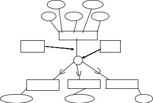
Figure 1. A generalization/specialization relationship
fname |
address |
BACKGROUND
A generalization/specialization relationship models a superclass/subclass type of relationship. A generalization is an abstraction mechanism that allows for viewing of entity-sets as a single generic entity-set. The attributes and associations which are common to the entity-sets are associated with the generic (generalized) entity-set. The inverse of generalization is called specialization.
ssn |
lname |
phone |
|
EMPLOYEE |
|
Partial |
|
Disjoint |
participation |
|
relationship |
|
d |
|
PHYSICIAN |
NURSE |
TECHNICIAN |
_ASSISTANT |
|
|
specialization |
department |
work |
Copyright © 2006, Idea Group Inc., distributing in print or electronic forms without written permission of IGI is prohibited.
TEAM LinG
cians or physician assistants are employees, but all employees are not technicians or physician assistants.
Figure 1 shows this generalization/specialization example. We use Elmasri and Navathe’s (2003) diagrammatic notations for the EER diagrams. The subset symbol, “ ”, indicates the direction of the superclass/subclass or parent-child, inheritance relationship. This superclass/ subclass relationship is also often referred to as a IS-A or IS-PART-OF relationship (Sanders, 1995).
Constraints on Generalization/ Specialization Relationships
Generalizations and specializations can have two types of constraints: (1) the disjoint/overlap relationship constraint and (2) participation constraints – total or partial. The combinations of these constraints can be (1) disjoint and total participation; (2) disjoint and partial participation; (3) overlap and total participation; or (4) overlap and partial participation. First we will discuss disjoint/overlap relationship constraints, and then we will discuss participation constraints, giving examples of combinations of the constraints along the way.
Disjoint/Overlap Relationship
Constraints
Generalization/specialization relationships may be disjoint or they may overlap. A disjoint relationship is shown by a “d” in the circle attaching the superclass to the subclass or subclasses (as shown in Figure 1). A disjoint relationship means that an entity from the superclass can belong to only one of the subclasses (can be of only one specialization). For example, according to Figure 1, an EMPLOYEE can be at most a member of only one of the subclasses – PHYSICIAN ASSISTANT, NURSE, or TECHNICIAN. An employee cannot be a physician assistant as well as a nurse, or cannot be a nurse as well as a technician.
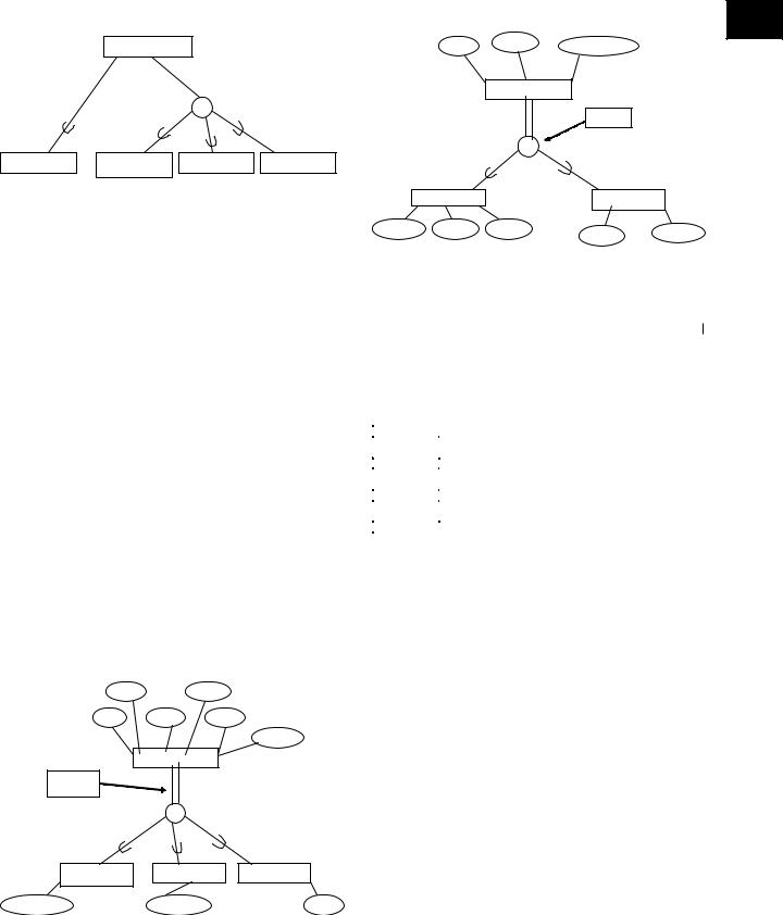
An overlap relationship is shown by an “o” in the circle attaching the superclass to the subclass or subclasses (as shown in Figure 4). Overlap means that an entity from the superclass can belong to more than one subclass (specialization). For example, according to Figure 4, a computer must be either a laptop or a desktop, or both a laptop and a desktop.
Participation Constraints
The second type of constraint on generalization/specialization relationships is participation constraints, which may be total (or full) or partial. As in the ER model (Bagui
Extended Entity Relationship Modeling
& Earp, 2003; Elmasri & Navathe, 2003), we will show a full or total participation between the superclass and subclass entities by double lines, and a partial participation between the superclass and subclass entities by single lines. Partial participation is shown in Figure 1. Figure 1 can be read as:
An EMPLOYEE may either be a PHYSICIAN ASSISTANT, NURSE, or TECHNICIAN.
Figure 1 shows a disjoint, partial participation relationship. The “may” means partial participation between the EMPLOYEE superclass and the respective subclasses entities. That is, not all employees of the EMPLOYEE entity set belong one of the subclasses, PHYSICIAN ASSISTANT, NURSE, or TECHNICIAN. One may ask, why? Or how? To answer this, we will extend Figure 1 to include another subclass, as shown in Figure 2. We now have an Employee from the EMPLOYEE entity set who may also belong to the HEAD subclass. Once again, the “may” is inferred from the single line between the superclass (or generalization) entity, EMPLOYEE, and the subclass (or specialization) entity, HEAD. Figure 2 can be read as:
An Employee may be a HEAD or PHYSICIAN ASSISTANT or NURSE or TECHNICIAN. Or, an Employee may be both a HEAD and a PHSYCIAN ASSISTANT, or both a HEAD and a NURSE, or both a HEAD and a TECHNICIAN.
An example of total or full participation is shown in Figure 3. We can read Figure 3 as:
An EMPLOYEE must either be a PHYSICIAN ASSISTANT, NURSE, or TECHNICIAN.
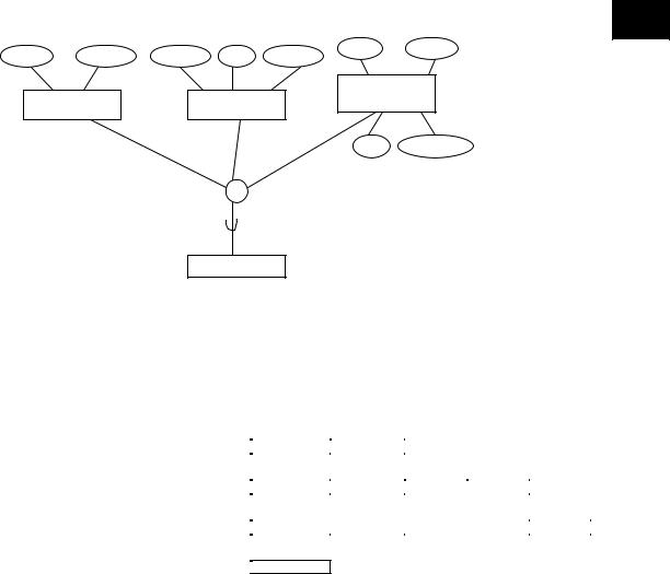
The “must” means total participation. So, an EMPLOYEE must belong to one of the subclasses. That is, all employees of the EMPLOYEE entity set must belong to one of the subclasses. But although there is total participation in Figure 3, the employee cannot belong to more than one subclass because of the “d” or disjoint relationship. Figure 3 shows a disjoint, full participation relationship, and Figure 4 shows an overlap, full participation relationship.
Mapping Generalizations and Specializations to a Relational Database
Rules to map generalizations/specializations to a relational database depend on the constraints on the generali-
234
TEAM LinG
Extended Entity Relationship Modeling
Figure 2. A disjoint
|
EMPLOYEE |
|
|
|
|
d |
|
HEAD |
PHYSICIAN |
NURSE |
TECHNICIAN |
|
ASSISTANT |
|
|
zation/specialization relationships. One of the following four rules are generally used (Elmsari & Navathe, 2003) to map generalizations and specializations to a relational database:
Figure 4. An overlap and full participation
E
|
make |
item_no |
item_model_no |
|
|
|
|
||
|
|
COMPUTER |
|
|
|
|
|
Overlap |
|
|
|
o |
|
|
|
LAPTOP |
|
DESKTOP |
|
fac_name |
weight |
fac_ssn |
building |
room_no |
|
|
|
||
|
|
|
|
Rule 1
Rule 1 works well for total or partial generalization/specialization relationships as well as disjoint or overlap generalization/specialization relationships. Using this rule, we would create a separate relation for the superclass as well as for each of the subclasses.
For rule 1:
1.Create a relation for the superclass entity. Include all the attributes of this entity in this relation and underline the primary key attribute.
2.Create a separate relation for each subclass (specialization) entity. Include the attributes of the respective subclasses in the respective subclass relations. Include the primary key from the superclass entity or relation in the subclass relation as the primary key of the subclass relation (and underline it).
Figure 3. A disjoint and full participation with predicate defined subclasses
fname |
address |
|
|
ssn |
lname |
phone |
|
|
|
|
job_type |
|
EMPLOYEE |
|
|
Full |
|
|
|
participation |
|
|
|
|
|
Job |
Type |
|
d |
|
|
"Physican_Assistant" |
|
|
"Technician" |
|
"Nurse" |
|
|
PHYSICIAN |
NURSE |
|
TECHNICIAN |
_ASSISTANT |
|
|
|
specialization |
department |
|
work |
To illustrate this rule, we will map Figure 1 as shown in the following example:
EMPLOYEE
ssn |
fname |
lname |
address |
phone |
PHYSICIAN ASSISTANT |
|
|
|
|
ssn |
specialization |
|
|
|
NURSE |
|
|
|
|
ssn |
department |
|
|
|
TECHNICIAN |
|
|
|
|
ssn |
work |
|
|
|
Rule 2
Rule 2 works well if: (a) there is total or full participation between the superclass and the subclasses. That is, if every member of the superclass entity set belongs to at least one of the subclasses; (b) if there is a disjoint relationship—otherwise there will be redundancy if a superclass entity belongs to more than one subclass; and (c) when there is more emphasis on the subclass (specialization), and it is more important to know about the subclass and its attributes. By this rule, we create a separate relation for each subclass. In this rule, you do not have a separate relation for the superclass entity.
For rule 2: Create a separate relation corresponding to each subclass entity. Include the attributes of the respective subclasses in the respective subclass relations. Also include the primary key and other attributes of the superclass entity in all the subclass relations. Underline the primary key brought from the superclass entity (to the subclass relation).
235
TEAM LinG

To illustrate this rule, we will map Figure 1 (but we are assuming that Figure 1 has full participation—double lines—between the EMPLOYEE superclass and the subclasses):
PHYSICIAN ASSISTANT
ssn |
specialization |
fname |
lname |
address |
phone |
NURSE |
|
|
|
|
|
ssn |
department |
fname |
lname |
address |
phone |
TECHNICIAN |
|
|
|
|
|
ssn |
work |
fname |
lname |
address |
phone |
Rule 3
Rule 3 works well if: (a) there is a disjoint relationship between the superclass and subclasses. It will create redundancy in the database if used with overlap scenarios. And, (b) if the subclasses are predicate defined (condition defined) or attribute defined. A predicate defined subclass is where a condition is placed on the value of some attribute of the superclass to determine the subclass. Figure 3 shows an example of a predicate defined subclass. If, as shown in Figure 3, the EMPLOYEE entity has an additional attribute, JobType, and a condition is specified on the condition of membership in the PHYSICIAN ASSISTANT subclass by the condition (jobType=”Physician_Assistant”), this is a defining predicate of the subclass, PHYSICIAN ASSISTANT. A predi- cate-defined subclass is shown by writing the predicate condition next to the arc that connects the subclass to the circle. Also, the defining attribute name is placed on the arc from the superclass to the circle. This rule is not recommended when subclasses have too many attributes (since this will cause too many null values).
For rule 3: Create a single relation that includes the superclass and its attributes as well as the subclasses and its attributes. For this rule, we will map Figure 3 as shown below:
EMPLOYEE
ssn |
fname |
lname |
address |
phone |
jobtype |
specialization |
department |
work |
|
|
|
|
|
|
|
|
|
Rule 4
Rule 4 works for both overlaps and disjoints, but it works better for overlaps. With disjoints, this rule will create null values when the entity is not a member of a particular subclass. This rule is also not recommended when subclasses have too many attributes (since this will also cause too many null values). If subclasses have few attributes, however, this rule may be preferred to rule 1 or rule 2 since it will eliminate the need for a relational join.
Extended Entity Relationship Modeling
In this rule, a flag is created for each superclass tuple that belongs to a subclass.
For rule 4: Create a single relation that includes the attributes of the superclass and the attributes of its subclasses. To illustrate this rule, we will map Figure 4 as shown below:
COMPUTER
item_no make item_model_no lflag fac_name weight fac_ssn dflag building room_no
CATEGORIES
The concept of categories extends the concepts of generalization entity types and specialization entity types even further. Categories are created by grouping entity types (generalization entity types or specialization entity types) by the roles they may play within relationships. So, categories can represent superclasses (generalization categories) or subclasses (specialization categories).
In Figure 5, the PAYOR could be inheriting from the PRIMARYINSURANCE,PATIENT,orOTHERRESPONSIBLE PARTY. The PRIMARY INSURANCE, PATIENT, and OTHER RESPONSIBLE PARTY represent a superclass (generalization category) of entity types. Each of the entity types in this generalization or superclass is a different entity type with different keys, but they play a common role – the role of a PAYOR. Here, we would refer to the subclass (in this case, PAYOR) as a category or union type of two or more superclasses. Hence, a category is a subclass of a union of two or more superclasses that are different entity types (Elmasri et al., 1985; Elmasri & Navathe, 2003) playing a common role. A category is diagrammatically shown by a “ ” in the circle that attaches the category to the superclasses, as shown in Figure 5. We can read Figure 5 as:
A PAYOR may be a PRIMARY INSURANCE or PATIENT or OTHER RESPONSIBLE PARTY.
Participation Constraints in Categories
Just like other subclasses, categories can also have total (or full) participation or partial participation. Total participation means that the category holds the union of all entities in its superclasses. That is, if there was full participation in Figure 5 (double lines running from the category, PAYOR, to the circle with the “ ”), then every entity of PRIMARY INSURANCE would exist in PAYOR, every entity of PATIENT would exist in PAYOR, and every entity of OTHER RESPONSIBLE PARTY would exist in PAYOR.
236
TEAM LinG
Extended Entity Relationship Modeling
Figure 5. A category
E
|
|
|
|
name |
address |
piname |
piaddress |
pname |
ssn |
paddress |
|
|
|
|
|
OTHER |
|
|
PRIMARY |
|
PATIENT |
RESPONSIBLE |
|
|
|
PARTY |
|
||
|
INSURANCE |
|
|
|
|
|
|
|
|
|
|
|
|
|
|
ssn |
relationship |
U
PAYOR
Partial participation means that a category holds only a subset of the union of all entities in its superclasses. That is, as shown in Figure 5, every entity of PRIMARY INSURANCE does not exist in PAYOR, every entity of PATIENT does not exist in PAYOR, and every entity of OTHER RESPONSIBLE PARTY does not exist in PAYOR. Once again, partial participation would be shown by single lines from the category to the circle with the “ ”.
Mapping Categories
There are two rules to map categories (Elmasri & Navathe, 2003).
To illustrate rule 5, we will map Figure 5 as shown below:
PRIMARY INSURANCE |
|
|
|
|
piname |
piaddress |
payorid |
|
|
PATIENT |
|
|
|
|
ssn |
paddress |
pname |
payorid |
|
OTHER RESPONSIBILITY PARTY |
|
|
||
ssn |
relationship |
name |
address |
payorid |
PAYOR
 payorid
Rule 5
Rule 5 should be used when the superclasses have different keys. For rule 5:
1.Create a new relation to correspond to the category.
2.Since the keys of each of the superclasses are different, we cannot use any one of them as the key for this new relation. So, we have to specify a new key attribute (called a surrogate key) to correspond to the category in the new relation.
3.To be able to join the subclass with the superclass/ superclasses, include the surrogate key attribute as the foreign key in each superclass relation.
Rule 6
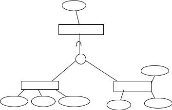
The second rule used to map categories is used when the superclass entities have the same key.
For example, we would map Figure 6 as:
DORM |
|
|
dormnu |
dname |
|
ON CAMPUS |
|
|
dormnu |
bldg |
supervisor |
OFF CAMPUS |
|
|
dormnu |
address |
manager |
237
TEAM LinG
Extended Entity Relationship Modeling
Figure 6. Category where superclasses have the same key
dname
DORM
|
|
U |
|
|
|
|
|
|
manager |
|
ON_CAMPUS |
|
OFF_CAMPUS |
|
dormnu |
bldg |
supervisor |
dormnu |
address |
|
|
|
||
|
|
|
|
Multiple Inheritance
In this article, we have given examples of how subclasses inherit from superclasses. In reality, however, subclasses often inherit from more than one superclass. This concept is known as multiple inheritance. Categories are also not necessarily disjoint, so a given entity may be a member of several different categories. Due to the brief nature of this paper, we will not elaborate on the concept of multiple inheritance.
CONCLUSION
Databases are becoming increasingly complex today. To deal with these complexities, it is becoming essential for database designers have to an understanding of the extended ER model, which incorporates generalizations/ specializations and categories. In this paper, we briefly presented generalizations/specializations and categories with the use of examples. We also presented rules to map generalizations/specializations and categories to a relational database.
FUTURE TRENDS
Due to the dominance of relational DBMSs and the intuitive nature of the ER approach, EER modeling is still being widely used. But, with the increasing trend towards ob- ject-oriented programming, the database world is likely to see an increase in the use of other models like ORM and UML in the future. ORMs view the world in terms of objects playing roles. ORMs are more expressive than ER models in capturing constraints or business rules and offer greater semantic stability than ER models (Halpin, 2001). Further advantages and disadvantages of ORM modeling are reported in Halpin (2000a, 2000b, 2001).
To date, UML is mainly used in industry for designing object-oriented program code (Halpin, 2001). Though sometimes used for designing databases, UML has so far had little success in displacing approaches such as ER and EER. Nevertheless, UML could very well become popular for database design in the future (Halpin, 2001). Further advantages and disadvantages of UML modeling versus ER modeling are reported in Halpin and Bloesch (1999); Hay (1999); Kobryn (1999); and Muller (1999).
REFERENCES
Bagui, S., & Earp, R. (2003). Database design using entityrelationship diagrams. Boca Raton, FL: CRC Press/ Auerbach.
Chen, P.P. (1976). The entity-relationship model: Toward a unified view of data. ACM Transactions of Database Systems, 1(1), 9-36.
Dey, D., Storey, V., & Barron, T. (1999). Improving database design through the analysis of relationships. ACM Transactions on Database Systems, 24(4), 453-486.
Elmasri, R., & Navathe, S.B. (2003). Fundamentals of database systems (4th ed.). Addison-Wesley.
Elmasri, R., Weeldreyer, J., & Hevner, A. (1985). The category concept: An extension to the entity-relationship model. Data and Knowledge Engineering, 1, 75-116.
Engels, G., Gogolla, M., Hohenstein, U., Hulsmann, K., Lohr-Richter, P., Saake, G., & Ehrich, H.-D. (1992/93).
238
TEAM LinG

Extended Entity Relationship Modeling
Conceptual modeling of database applications using an extended ER model. Data and Knowledge Engineering, 9, 157-204.
Halpin, T.A. (2000a). An ORM metamodel. Journal of Conceptual Modeling, 9.
Halpin, T.A. (2000b). An ORM metamodel of Barker ER.
Journal of Conceptual Modeling, 9.
Halpin, T.A. (2001). Information modeling and relational databases. Morgan Kaufmann.
Halpin, T.A., & Bloesch, A.C. (1999). Data modeling in UML and ORM: A comparison. Journal of Database Management, 10(4), 4-13.
Hay, D.C. (1999). There is no object-oriented analysis.
DataToKnowledge Newsletter, 27(1).
Kobryn, C. (1999). UML 2001: A standardization odyssey.
Communication of the ACM, 42(10), 29-37.
Markowitz, V., & Shoshani, A (1992). Representing extended entity-relationship structures in relational databases: A modular approach. ACM Transactions on Database Systems, 17(3), 423-464.
Muller, R.J. (1999). Database design for smarties. San Francisco: Morgan Kaufmann.
Sanders, L.G. (1995). Data modeling. Thomson International.
Song, I.Y., Evans, M., & Park, E.K. (1995). A comparative analysis of entity-relationship diagram. Journal of Computer and Software Engineering, 3(4), 427-459.
Wiederhold, G., & Elmasri, R. (1980). The structural model for database design. In P.P. Chen (Ed.), Entity-relation- ship approach to systems analysis and design. Amsterdam: North-Holland.
KEY TERMS
E
Category: A collection of objects or entities that is a subset of the union of different entity types; entities offering a similar role are grouped into a category.
Entity Sets or Entity Types: Similar entities or objects with common properties are summarized into entity sets or entity types; graphically represented in rectangles.
Generalization: When entities have similar basic attributes, they can be classified into a generalized entity type. Generalization is the process of finding commonalities between entities to be able to abstract to a higher level entity set.
Inheritance: A subclass inherits all the attributes of a superclass and all the relationships that it (the superclass) participates in.
Specialization: A process of conceptual refinement to form specialized subclasses for entity sets. An entity type can have several specializations or categories of specializations defined on the basis of some distinguishing characteristics of the entities in the superclass.
Subclass: Same as specialization; a meaningful subgrouping of entity sets that needs to be represented explicitly. These subgroups are a subset of the entities that belong to the entity set from which they are derived.
Superclass: Same as generalization. A superclass is the main set (entity) from which subsets (subclasses) are defined based on meaningful criteria needed for a particular database.
239
TEAM LinG