

Richards M.The BCPL Cintcode and Cintpos user guide.2005
.pdf6.8. DISCUSSION |
93 |
The end of an OCODE module is marked by the GLOBAL statement which contains information about global procedures and labels. The form of the GLOBAL statement is as follows:
GLOBAL nK1L1 : : : KnLn
where n is the number of items in the global initialisation list. Ki is the global number and Li is its label. When a module is loaded its global entry points must be initialised.
6.8Discussion
A very early version of OCODE used a three address code in which the operands were allowed to be the sum of up to three simple values with a possible indirection. The intention was that reasonable code should be obtainable even when codegenerating one statement at a time. It was soon found more convenient to use an intermediate code that separates the accessing of values from the application of operators. This improved portability by making it possible to implement very simple non optimising codegenerators. Optimising codegenerators could absorb several OCODE statements before emitting compiled code.
The TRUE and FALSE statements were added in 1968 to improve portability to machines using sign and modulus or one's complement arithmetic. Luckily two's complement arithmetic has now become the norm. Other extension to OCODE, notably the ABS, QUERY, GETBYTE and PUTBYTE statements were added as the corresponding constructs appeared in the language.
In 1980, the BCPL changed slightly to permit position independent code to be compiled. This change speci¯ed that non global labels and procedures were no longer variables, and the current version of OCODE re°ects this change by the introduction of the LF statement and the removal of the old ITEML statement that used to allocate static cells for such entry points.
Another minor change in this version of OCODE is the elimination of the ENDFOR statement that was provided to ¯x a problem on 16-bit word addressed machines with more than 64 Kbytes of memory.
94 |
CHAPTER 6. THE DESIGN OF OCODE |
Chapter 7
The Design of Cintcode
The original version of Cintcode was a byte stream interpretive code designed to be both compact and capable of e±cient interpretation on small 16 bit machines machines based on 8 bit micro processors such as the Z80 and 6502. Versions that ran on the BBC Microcomputer and under CP/M were marketed by RCP Ltd [2]. The current version of Cintcode was extended for 32 bit implementations of BCPL and mainly di®ers from the original by the provision of 32 bit operands and the removal of a size restriction of the global vector.
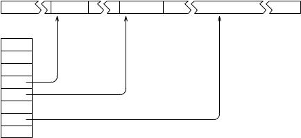
The Cintcode machine has eight registers as shown in ¯gure 7.1.
Stack frame |
Global vector |
Program area |
Registers
A
B
C
P
G
ST
PC
Count
Figure 7.1: The Cintcode machine
The registers A and B are used for expression evaluation, and C is used in in byte subscription. P and G are pointers to the current stack frame and the global vector, respectively. ST was intended as a status register but is currently not used, and PC points to the ¯rst byte of the next Cintcode instruction to execute. Count is a register used by the debugger. While it is positive, Count is decremented on each instruction execution, raising an exception (code 3) on reaching zero. When negative it causes a second (faster) interpreter to be used.
95
96 |
CHAPTER 7. THE DESIGN OF CINTCODE |
Cintcode encodes the most commonly occurring operations as single byte instructions, using multi-byte instructions for rarer operations. The ¯rst byte of an instruction is the function code. Operands of size 1, 2 or 4 bytes imediately follow some function bytes. The two instructions used to implement switches have inline data following the function byte. Cintcode modules also contains static data for stings, integers, tables and global initialisation data.
7.1Designing for Compactness
To obtain a compact encoding, information theory suggests that each function code should occur with approximately equal frequency. The self compilation of the BCPL compiler, as shown in ¯gure 4.2, was the main benchmark test used to generate frequency information and a summary of how often various operations are used during this test is given in table 7.1. This data was produced using the tallying feature controlled by the stats command, described on page 74.
Operation |
Executions |
Static count |
|
|
|
Loading a local variable |
3777408 |
1479 |
Updating a local variable |
1965885 |
1098 |
Loading a global variable |
|
1759 |
5041968 |
||
Updating a global variable |
796761 |
363 |
Using a positive constant |
|
1603 |
4083433 |
||
Using a negative constant |
160224 |
93 |
Conditional jumps (all) |
2013013 |
488 |
Conditional jumps on zero |
|
267 |
494282 |
||
Unconditional direct jump |
254448 |
140 |
Unconditional indirect jumps |
152646 |
93 |
Procedure calls |
|
1065 |
1324206 |
||
Procedure returns |
1324204 |
381 |
Binary chop switches |
43748 |
12 |
Label vector switches |
|
17 |
96461 |
||
Addition |
2135696 |
574 |
Subtraction |
|
111 |
254935 |
||
Other expression operations |
596882 |
74 |
Loading a vector element |
1356315 |
429 |
Updating a vector element |
591268 |
137 |
Loading a byte vector element |
|
53 |
476688 |
||
Updating a byte vector element |
405808 |
29 |
|
|
|
Table 7.1: Counts from the BCPL self compilation test
The statistics from di®erent programs vary greatly, so while encoding the common operations really compactly, there is graceful degradation for the rarer cases ensuring that even unusual programs are handled reasonably well. There are, for instance, several one byte instructions for loading small integers, while larger integers are handled using 2, 3 and 5 byte instructions. The intention is that small changes in a source program should cause small small changes in the size of the corresponding compiled code.
7.1. DESIGNING FOR COMPACTNESS |
97 |
Having several variant instructions for the same basic operation does not greatly complicate the compiler. For example the four variants of the AP instruction that adds a local variable into register A is dealt with by the following code fragment taken from the codegenerator.
TEST 3<=n<=12 THEN gen(f_ap0 + n)
ELSE TEST 0<=n<=255
THEN genb(f_ap, n)
ELSE TEST 0<=n<=#xFFFF
THEN genh(f_aph, n)
ELSE genw(f_apw, n)
It is clear from table 7.1 that accessing variables and constants requires special care, and that conditional jumps, addition, procedure calls and indirection are also important. Since access to local variables accounts for about a quarter of the operations performed, about this proportion of codes were allocated to instructions concerned with local variables. Local variables are allocated words in the stack starting at position 3 relative to the P pointer and, as one would expect, small numbered locals are used far more frequently than the others, so operations on low numbered locals often have single byte codes.
Although not shown here, other statistics, such as the distribution of relative addressing o®sets and operand values, in°uenced the design of Cintcode.
7.1.1Global Variables
Global variables are referenced as frequently as locals and therefore have many function codes to handle them. The size of the global vector in most programs is less than 512, but Cintcode allows this to be as large are 65536 words. Each operation that refers to a global variable is provided with three related instructions. For instance, the instructions to load a global into register A are as follows:
LG |
b |
|
B := A; A := |
G!b |
|
|
|
|
|
|
|
|
|
|
|
|
|
LG1 |
b |
|
B := |
A; A := |
G!(b+256) |
|
|
|
|
|
|
|
|
|
|
|
|
LGH |
h |
B := |
A; A := |
G!h |
|
|
|
|
|
|
|
98 |
CHAPTER 7. THE DESIGN OF CINTCODE |
Here, b and h are unsigned 8 and 16 bit values, respectively.
7.1.2Composite Instructions
Compactness can be improved by combining commonly occurring pairs (and triples) of operations into a single instructions. Many such composite instructions occur in Cintcode; for instance, AP3 adds local 3 to the A register, and L1P6 will load v!1 into register A, assuming v is held in local 6.
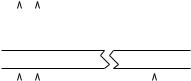
7.1.3Relative Addressing
A relative addressing mechanism is used in conditional and uncoditional jumps and the instructions: LL, LLL, SL and LF. Al these instructions refer to locations within the code and are optimised for small relative distances. To simplify the codegenerator all relative addressing instructions are 2 bytes in length. The ¯rst being the function code and the second being an 8 bit relative address.
Direct |
|
|
J |
|
a |
|
|
|
|
|
dest |
= |
x |
+ a |
||
|
|
|
|
|
|
|
|
|
|
|
||||||
|
|
|
|
|
|
|
|
|
|
|
|
|
|
|
|
|
|
|
|
|
|
|
|
|
|
|
|
|
|
|
|
|
|
|
|
|
|
|
|
|
|
|
|
|
|
|
|
|
|
|
|
|
|
PC |
|
x |
|
|
|
|
|
|
|
|
|||
Indirect |
|
J$ |
|
b |
|
|
|
hh |
|
dest |
= |
q |
+ hh |
|||
|
|
|
|
|
|
|||||||||||
|
|
|
|
|
|
|
|
|
|
|
|
|||||
|
|
|
|
|
|
|
|
|
|
|
|
|
||||
|
|
|
PC |
|
x |
|
q = (x & #xFFFFFFFE) + 2*b |
|||||||||
Figure 7.2: The relative addressing mechanism
All relative addressing instructions have two forms: direct and indirect, depending on the least signi¯cant bit of the function byte. The details of both relative address calculations are shown in ¯gure 7.2, using the instructions J and J$ as examples. For the direct jump (J), the operand (a) is a signed byte in the range -128 to +127 which is added to the address (x) of the operand byte to give the destination address (dest). For the indirect jump, J$, the operand (b) is an unsigned byte in the range 0 to 255 which is doubled and added to the rounded version of x to give the address (q) of a 16 bit signed value hh which is added to q to give the destination address (dest).

7.2. THE CINTCODE INSTRUCTION SET |
99 |
The compiler places the resolving half word as late as possible to increase the chance that it can be shared by other relative addressing instructions to the same desination, as could happen when several ENDCASE statements occur in a large SWITCHON command. The use of a 16 bit resolving word places a slight restriction on the maximum size of relative references. Any Cintcode module of less than 64K bytes will have no problem.
7.2The Cintcode Instruction Set
The resulting selection of function codes is shown in Table 7.2 and they are described in the sections that follow. In the remaining sections of this chapter the following conventions hold:
Symbol Meaning
nAn integer encoded in the function byte.
Ln The one byte operand of a relative addressing instruction.
bAn unsigned byte, range 0 · b · 255.
h An unsigned halfword, range 0 · h · 65535.
wA signed 32 bit word.
¯ller Optional ¯ller byte to round up to a 16 bit boundary. A The Cintcode A register.
B The Cintcode B register. C The Cintcode C register. P The Cintcode P register. G The Cintcode G register.
PC The Cintcode PC register.
7.2.1Byte Ordering and Alignment
A Cintcode module is a vector of 32 bit words containing the compiled code and static data of a section of program. The ¯rst word of a module holds its size in words that is used as a relative address to the end of the module where the global initialisation data is placed. The last word of a module holds the highest referenced global number, and working back, there are pairs of words giving the global number and relative entry address of each global function or label de¯ned in the module. A relative address of zero marks the end of the initialisation data. See section 6.3 for more details.
The compiler can generate code for either a bigor little-endian machine. These di®er only in the byte ordering of bytes within words. For a little endian machine, the ¯rst byte of a 32 bit word is at the least signi¯cant end, and on a big-endian machine, it is the most signi¯cant byte. This a®ect the ordering of bytes in 2 and 4 byte immediate operands, 2 byte relative address resolving words, 4 byte static quantities and global initialisation data. Resolving words are aligned on 16 bit boundaries relative to the start of the module, and 4 byte statics values are aligned on 32 bit boundaries. The 2 and 4 byte immediate operands are not aligned.
100 |
CHAPTER 7. THE DESIGN OF CINTCODE |
|
0 |
32 |
64 |
96 |
128 |
160 |
192 |
224 |
|
|
|
|
|
|
|
|
|
|
|
0 |
- |
K |
LLP |
L |
LP |
SP |
AP |
A |
|
1 |
- |
KH |
LLPH |
LH |
LPH |
SPH |
APH |
AH |
|
2 |
BRK |
KW |
LLPW |
LW |
LPW |
SPW |
APW |
AW |
|
3 |
K3 |
K3G |
K3G1 |
K3GH |
LP3 |
SP3 |
AP3 |
L0P3 |
|
4 |
K4 |
K4G |
K4G1 |
K4GH |
LP4 |
SP4 |
AP4 |
L0P4 |
|
5 |
K5 |
K5G |
K5G1 |
K5GH |
LP5 |
SP5 |
AP5 |
L0P5 |
|
6 |
K6 |
K6G |
K6G1 |
K6GH |
LP6 |
SP6 |
AP6 |
L0P6 |
|
7 |
K7 |
K7G |
K7G1 |
K7GH |
LP7 |
SP7 |
AP7 |
L0P7 |
|
8 |
K8 |
K8G |
K8G1 |
K8GH |
LP8 |
SP8 |
AP8 |
L0P8 |
|
9 |
K9 |
K9G |
K9G1 |
K9GH |
LP9 |
SP9 |
AP9 |
L0P9 |
|
10 |
K10 |
K10G |
K10G1 |
K10GH |
LP10 |
SP10 |
AP10 |
L0P10 |
|
11 |
K11 |
K11G |
K11G1 |
K11GH |
LP11 |
SP11 |
AP11 |
L0P11 |
|
12 |
LF |
S0G |
S0G1 |
S0GH |
LP12 |
SP12 |
AP12 |
L0P12 |
|
13 |
LF$ |
L0G |
L0G1 |
L0GH |
LP13 |
SP13 |
XPBYT |
S |
|
14 |
LM |
L1G |
L1G1 |
L1GH |
LP14 |
SP14 |
LMH |
SH |
|
15 |
LM1 |
L2G |
L2G1 |
L2GH |
LP15 |
SP15 |
BTC |
MDIV |
|
16 |
L0 |
LG |
LG1 |
LGH |
LP16 |
SP16 |
NOP |
CHGCO |
|
17 |
L1 |
SG |
SG1 |
SGH |
SYS |
S1 |
A1 |
NEG |
|
18 |
L2 |
LLG |
LLG1 |
LLGH |
SWB |
S2 |
A2 |
NOT |
|
19 |
L3 |
AG |
AG1 |
AGH |
SWL |
S3 |
A3 |
L1P3 |
|
20 |
L4 |
MUL |
ADD |
RV |
ST |
S4 |
A4 |
L1P4 |
|
21 |
L5 |
DIV |
SUB |
RV1 |
ST1 |
XCH |
A5 |
L1P5 |
|
22 |
L6 |
REM |
LSH |
RV2 |
ST2 |
GBYT |
RVP3 |
L1P6 |
|
23 |
L7 |
XOR |
RSH |
RV3 |
ST3 |
PBYT |
RVP4 |
L2P3 |
|
24 |
L8 |
SL |
AND |
RV4 |
STP3 |
ATC |
RVP5 |
L2P4 |
|
25 |
L9 |
SL$ |
OR |
RV5 |
STP4 |
ATB |
RVP6 |
L2P5 |
|
26 |
L10 |
LL |
LLL |
RV6 |
STP5 |
J |
RVP7 |
L3P3 |
|
27 |
FHOP |
LL$ |
LLL$ |
RTN |
GOTO |
J$ |
ST0P3 |
L3P4 |
|
28 |
JEQ |
JNE |
JLS |
JGR |
JLE |
JGE |
ST0P4 |
L4P3 |
|
29 |
JEQ$ |
JNE$ JLS$ JGR$ |
JLE$ |
JGE$ |
ST1P3 |
L4P4 |
|||
30 |
JEQ0 |
JNE0 |
JLS0 |
JGR0 |
JLE0 |
JGE0 |
ST1P4 |
- |
|
31 |
JEQ0$ |
JNE0$ |
JLS0$ |
JGR0$ |
JLE0$ |
JGE0$ |
- |
- |
|
|
|
|
|
|
|
|
|
|
|
Table 7.2: The Cintcode function codes
7.2. THE CINTCODE INSTRUCTION SET |
101 |
For e±ciency reasons, the byte ordering is chosen to suit the machine on which the code is to be interpreted. The compiler option OENDER causes the BCPL compiler to compile code with the opposite endianess to that of the machine on which the compiler is running, see the description of the bcpl command on page 65.
7.2.2Loading values
The following instructions are used to load constants, variables, the addresses of variables and function entry points. Notice that all loading instructions save the old value of register A in B before updating A. This simpli¯es the translation of dyadic expression operators.
Ln |
0 · n · 10 |
B := A; A := n |
LM1 |
|
B := A; A := -1 |
L b |
|
B := A; A := b |
LH h |
|
B := A; A := h |
LMH h |
|
B := A; A := -h |
LW w |
|
B := A; A := w |
These instructions load integer constants. Constants are in the range -1 to 10 are the most common and have single byte instructions. The other cases use successively larger instructions.
LPn |
3 · n · 16 |
B := A; A := |
P!n |
|
LP b |
|
B := A; A := |
P!b |
|
LPH h |
|
B |
:= A; A := |
P!h |
LPW w |
|
B |
:= A; A := |
P!w |
These instructions load local variables and anonymous results addressed relative to P. O®sets in the range 3 to 16 are the most common and use single byte instructions. The other cases use succesively larger instructions.
LG b |
B := A; A |
:= G!b |
||
LG1 b |
B := A; |
A |
:= |
G!(b + 256) |
LGH h |
B := A; |
A |
:= |
G!h |
LG loads the value of a global variables in the range 0 to 255, LG1 load globals in the range 256 to 511, and LGH can load globals up to 65535. Global numbers must be in the range 0 to 65535.
LL Ln |
B := A; A := |
variable |
Ln |
|
||
LL$ Ln |
B := A; A := |
variable |
Ln |
|
||
LF Ln |
B := A; |
A |
:= |
entry point |
Ln |
|
LF$ Ln |
B := A; |
A |
:= |
entry point |
Ln |
|
LL loads the value of a static variable and LF loads the entry address of a function, routine or label in the current module.
LLP b |
B := A; A := @P!b |
102 |
CHAPTER 7. THE DESIGN OF CINTCODE |
LLPH h |
B := A; A := @P!h |
LLPW w |
B := A; A := @P!w |
LLG b |
B := A; A := @G!b |
LLG1 b |
B := A; A := @G!(b + 256) |
LLGH h |
B := A; A := @G!h |
LLL Ln |
B := A; A := @(variable Ln) |
LLL$ Ln |
B := A; A := @(variable Ln) |
These instructions load the BCPL ponters to local, global and static variables.
7.2.3Indirect Load
GBYT |
|
|
RV |
|
· n · 6 |
RVn |
1 |
|
RVPn |
3 |
· n · 7 |
L0Pn |
3 |
· n · 12 |
L1Pn |
3 |
· n · 6 |
L2Pn |
3 |
· n · 5 |
L3Pn |
3 |
· n · 4 |
L4Pn |
3 |
· n · 4 |
LnG b |
0 |
· n · 2 |
LnG1 b |
0 |
· n · 2 |
LnGH h |
0 |
· n · 2 |
A := B%A
A := A!0 A := A!n
A := P!n!A
B := A; A := P!n!0 B := A; A := P!n!1 B := A; A := P!n!2 B := A; A := P!n!3 B := A; A := P!n!4 B := A; A := G!b!n
B := A; A := G!(b+256)!n B := A; A := G!h!n
These instructions are used in the implementation of byte and word indirection operators % and ! in right hand contexts.
7.2.4Expression Operators
NEQ |
A := -A |
|
ABS |
A := |
ABS A |
NOT |
A := |
~A |
These instructions implement the three monadic expression operators.
MUL |
A := B * A |
DIV |
A := B / A |
REM |
A := B REM A |
ADD |
A := B + A |
SUB |
A := B - A |
LSH |
A := B << A |
RSH |
A := B >> A |
AND |
A := B & A |
OR |
A := B | A |