Rasmussen H.Automatic tuning of PID-regulators
.pdfAutomatic Tuning
of
PID-regulators
H. Rasmussen
Aalborg University, Dept. of Control Engineering
Fredrik Bajers Vej 7
DK 9220 Aalborg, Denmark
September 6, 2002
Contents
1 |
Introduction |
3 |
2 |
Digital PID regulators |
3 |
3 |
Ziegler-Nichols tuning methods |
10 |
4 |
Auto Tuning based on relay feedback |
12 |
5 |
Tuning with specified phase and amplitude margin |
15 |
6 |
Relay with hysteresis |
17 |
7 |
Offset |
18 |
8 |
Auto Tuning based on Pole Placement |
18 |
References |
21 |
|
1
2
Preface.
This text summarizes digital PID control and methods for automatic tuning based on relay feedback. The text is intended for use as a part of a graduate course in Adaptive Control and the topics are selected from the references with this in mind.
1 INTRODUCTION |
3 |
1 Introduction
Many process control problems can be adequately and routinely solved by conventional PID-control strategies. The overriding reason that the PID controller is so widely accepted is its simple structure which has proved to be very robust with regard to many commonly met process control problems as for instance disturbances and nonlinearities. Tuning of the PID settings is quite a subjective procedure, relying heavily on the knowledge and skill of the control engineer or even plant operator. Although tuning guidelines are available, the process of controller tuning can still be time consuming with the result that many plant control loops are often poorly tuned and full potential of the control system is not achieved. One way of deriving a self-tuning control law with the structure of a PID controller is to approximate the system with a parameterized model of order or and calculate the controller coefficients using a design method as e.g. pole placement, generalized predictive control or LQG. These methods are easily extended to a higher order with possibility of better control performance. They require a fair amount of a priori knowledge as for instance sampling period, dead time, model order, and desired response time. This knowledge may either be given by a skilled engineer or may be acquired automatically by some kind of experimentation. The latter alternative is preferable, not only to simplify the task of the operator, but also for the sake of robustness.
A key method for auto-tuning (Astr¨om˚ and H¨agglund 1988) is to use relay feedback. Processes with the dynamics typically encountered in process control will then exhibit limit cycle oscillations and the auto tuner identifies one point on the Nyquist curve of the process from the experiment. When the operator decides to tune the controller, he simply presses a button starting a relay experiment. The relay feedback causes the process to oscillate with a controlled amplitude. The frequency of the limit cycle
is approximately the ultimate frequency where the process has a phase lag of . The ratio of the amplitude of limit cycle and the relay amplitude is approximately the process gain at that frequency. Thus a point on the Nyquist curve of the open loop dynamics close to the ultimate point is determined. A reasonable PID controller based
on this point may then be calculated.
2 Digital PID regulators
The ”textbook” version of the PID controller can be described by the equation
|
|
$ |
|
% |
|
||
() * # () + +, ( |
|||
!#" |
|
(1) |
|
|
' |
||
!",./*- ,
where is the set point and is the process output. The PID controller was originally implemented using analog technology that went through several development stages.
2 DIGITAL PID REGULATORS |
4 |
In this development much know-how was accumulated imbedded into the analog design. Today, virtually all PID-regulators are implemented digitally. Early implementations were often a pure translation of equation 1 which left out many of the extra features that were incorporated in the analog design. The following implementation is discussed in detail in (Astr¨om˚ and Wittenmark, 1990).
Modification of ”textbook” version.
A pure derivative cannot and should not be implemented, because it will give a very large amplification of measurement noise. The gain of the derivative must thus be limited. This can be done by low-pass filtering the derivative term, resulting in a limited gain N at high frequencies. N is typically in the range of 3-20. In the work with analog controllers it was found advantageous not to let the derivative act on the command signal. It was also found suitable to let only a fraction of the command signal act on the proportional part. Introducing the derivative operator ,,the PID-algorithm then becomes
* + |
|
|
/ * |
||||
|
|||||||
|
|
|
!#" |
(2) |
|||
|
!" |
|
|
|
|
||
|
|
|
|
|
|
|
|
! |
|
|
|||||
The different signal paths for the command |
signal and the process output in this |
||||||
equation gives different closed loop zeros which separate command signal response from the response from disturbances.
Discretization.
Any standard transformation method can be used in the discretization of equation (2). The following is a popular approximation that is easy to derive.
The proportional part |
|
(3)
requires no transformation since it is purely static.
The integral part
! " $() * # () + +, (
The integration is approximated by |
|
|
|
|
||
|
$ |
|
$ |
$ |
|
|
/ /() () + , ( |
/ /() /() , ( $ |
/ /() /() , ( |
||||
|
|
|
$/ /() /() , ( + |
|
||
which gives the following (forward euler) time discretization: |
|
|
||||
|
. * |
(4) |
||||
|
|
|
|
! " |
|
|

2 DIGITAL PID REGULATORS |
|
|
|
|
|
|
|
|
|
|
|
|
|
|
|
|
|
|
|
|
|
|
5 |
|||||||||||||||||||||
|
|
|
|
|
|
|
|
|
|
|
|
|
|
|
|
Table 1: RST-coefficients |
|
|
|
|
|
|
|
|
|
|
|
|||||||||||||||||
|
|
|
|
|
|
|
|
|
|
|
|
|
|
|
|
|
|
|
|
|
|
|
|
|
|
|
|
|
|
|
|
|
|
|
|
|
|
|
|
|
||||
|
|
|
|
|
|
|
|
|
|
|
|
|
|
|
|
|
|
|
|
|
|
|
|
|
|
|
|
|
|
|
|
|
|
|||||||||||
|
|
|
|
|
|
|
|
|
|
|
|
|
|
|
|
|
|
|
|
|
|
|
|
|
|
" |
|
|
|
|
|
|
|
|
|
|
||||||||
|
|
|
|
|
|
|
|
|
|
|
|
|
|
|
|
|
|
|
|
|
|
|
|
|
|
|
|
|
|
|
|
|
|
|
|
|
|
|
|
|||||
|
|
|
|
|
|
|
|
|
|
|
|
|
|
|
|
|
|
|
|
|
|
|
|
|
|
|
|
|
|
|
|
|
|
|
|
|
|
|||||||
|
|
|
|
|
|
|
|
|
|
|
|
|
|
|
|
|
|
|
|
|
|
|
|
|
|
|
|
|
|
|
|
|||||||||||||
|
|
|
|
|
|
|
|
|
|
|
|
|
|
|
|
|
|
|
|
|
|
|
|
|
||||||||||||||||||||
|
|
|
|
|
|
|
|
|
|
|
|
|
|
|
|
|
|
|
|
" |
|
|
|
|
|
|
|
" |
|
|
||||||||||||||
|
|
|
|
|
|
|
|
+ |
|
|
|
|
|
|
|
|
||||||||||||||||||||||||||||
|
|
|
|
|
|
|
|
|
|
|
|
|
|
|
|
|
|
|
|
|
|
|
|
|
|
|
|
|
|
|
|
|
|
|
|
|
||||||||
|
|
|
|
|
|
|
|
|
|
|
|
|
|
|
|
|
|
|
|
|
" |
|
|
|
|
|
" |
|
|
|
|
|||||||||||||
|
|
|
|
|
|
|
|
|
+ |
|
|
|
|
|
|
|
|
|
|
|
|
|||||||||||||||||||||||
The derivative part |
|
|
|
|
|
|
|
|
|
|
|
|
|
|
|
|
|
|
|
|
|
|
|
|
|
|
|
|
|
|
|
|
|
|
||||||||||
|
|
|
|
|
|
|
|
|
|
|
|
! |
|
|
, |
|
|
|
|
|
|
|
|
|
|
|
|
|
, |
|
|
|
|
|
|
|
|
|
|
|||||
|
|
|
|
|
|
|
|
|
|
|
|
|
|
|
|
|
|
|
|
|
|
|
|
|
|
|
|
|
|
|
|
|
|
|
|
|||||||||
|
|
|
|
|
|
|
|
|
|
|
|
|
|
|
|
|
|
|
|
|
|
! |
|
|
|
|
|
|
|
|
|
|
|
|||||||||||
|
|
|
|
|
|
|
|
|
|
|
|
|
|
, |
|
|
|
|
|
|
|
|
|
|
|
|
|
|
|
|
|
|
|
|
|
|
||||||||
|
|
|
|
|
|
|
|
|
|
|
|
|
|
|
|
, |
|
|
|
|
|
|
|
|
|
|
|
|||||||||||||||||
is approximated by taking backward differences |
|
|
|
|
|
|
|
|
|
|
|
|
|
|
|
|
||||||||||||||||||||||||||||
|
|
|
|
|
! |
|
|
|
|
|
|
|
. |
|
|
|
|
|
! |
# * #. |
|
|
|
|
|
|
||||||||||||||||||
|
|
|
|
|
|
|
|
|
|
|
|
|
|
|
|
|
|
|
|
|
||||||||||||||||||||||||
|
|
|
|
|
|
|
|
|
|
|
|
|
|
|
|
|
|
|
|
|
|
|
|
|
|
|
|
|
|
|||||||||||||||
which give the following approximation: |
|
|
|
|
|
|
|
|
|
|
|
|
|
|
|
|
|
|
|
|
||||||||||||||||||||||||
|
|
|
|
|
! |
. |
! |
# |
|
|
|
(5) |
||||||||||||||||||||||||||||||||
|
|
|
|
|
|
|
|
|
|
|
! |
|
|
|
|
|
|
|
|
|
|
|
|
! |
|
|
|
|
|
|
|
|
|
|
|
|
|
|
|
|
||||
If the delay operator & defined as & # .is introduced, then combining equation (3),(4) and (5) gives the control signal
|
|
* |
& |
|||||||||||||||
|
|
|
|
|
|
|
|
!" |
|
|
& |
|
|
|
|
|
|
|
|
|
|
|
|
|
|
|
|
|
|
|
|
|
|
|
(6) |
||
|
|
|
|
|
|
|
|
! |
|
& |
||||||||
|
|
|
|
|
|
|
|
! |
|
|
|
|
& |
|
|
|
||
|
|
|
|
|
|
|
|
|
|
|
|
|
|
|
|
|
|
|
Equation (6) can after some calculations be written as |
|
|
|
|
|
|
||||||||||||
|
|
|
|
|
|
|
|
|||||||||||
+ |
! & |
! & |
& |
& |
|
|
" |
& |
#& |
|||||||||
|
|
|
|
|
|
|
|
|
|
|
|
|||||||
|
|
|
|
|
|
|
|
|
|
|
|
|
(7) |
|||||
with coefficients given by table 1. Polynomial operators defined by:
$ & % & ! &
& &
& &#
& &
gives the following short form operator description of the PID regulator: |
|
$ & ! & % & |
(8) |

2 DIGITAL PID REGULATORS |
6 |
a) |
A 0 |
- |
R |
b) |
|
1 |
v |
u |
|
|
|
|
y r |
|
|||
|
|
|
- |
T |
A 0 |
|
|
|
|
|
|
|
|
|
|||
y r |
T |
1 |
v |
u |
A 0 |
- |
R |
|
|
R |
|
|
|
||||
|
|
|
|
|
|
|
|
|
|
- S |
y |
|
- S |
|
y |
||
|
|
|
|
|
||||
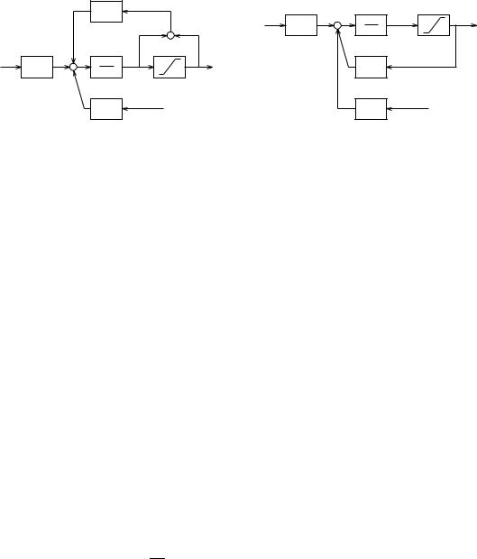
Figure 1: Regulator with anti integrator windup and a) measured actuator output b) estimated actuator output
Other realizations of ! & are often seen in the literature. Among the most common are
!& #
!& % &
Integrator windup and bumpless transfer
If the control error is so large that the control output saturates the actuator, the feedback path will be ”broken”, because the actuator remains saturated even if the process output changes. The integrator may then integrate up to a very large value. When the error is finally reduced, the integral may be so large that it takes a considerable time to reach a normal value again. This effect is called integrator windup and one way to avoid it is shown in figure 1.a. An extra feedback path is provided in the controller by measuring the actuator output and forming an error signal , which is filtered and fed back through the integrator part of the controller $ & . The error signal is zero when the actuator is not saturated and the block diagram gives equation
(8). When the actuator saturates, the feedback signal will attempt to drive the error to zero, preventing the integrator from winding up. The filter determines how quickly the integral is reset. If the actuator output cannot be measured, the anti-windup scheme can be applied by incorporating a mathematical model of the saturating actuator. In this case the block diagram in figure 1.b gives the following equations:
|
$ ! % |
||
|
|
|
|
|
|
|
|
If the regulator output in manual mode is given by bumpless transfer from manual mode to controller mode is achieved by using
in manual mode, and then switching to the specified values for and in controller mode.
2 DIGITAL PID REGULATORS |
7 |
bumpless transfer from controller mode to manual mode is achieved by resetting
as follows:

2 DIGITAL PID REGULATORS |
8 |
Example 1 Influence of observer polynomial & .
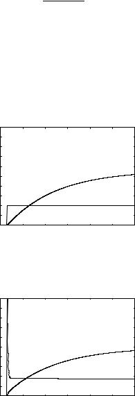
Figure 2 shows the open loop response for the system:
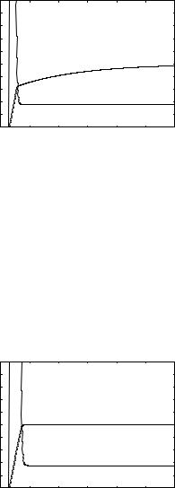
A PI-regulator with very short sampling time ! and the parameters, !" )and is discretized by the transformations given in table 1 and the closed loop step response is shown in figure 3 with an observer polynomial - .
Figure 4 and figure 5 show the effect of a first order |
observer polynomial |
& ! !$ & with time constant !$ |
!"and !$ !". |
Comparing figure 3 and figure 5 shows the importance of the observer polynomial for fast sampled systems.
|
10 |
|
|
|
|
|
|
|
9 |
|
|
|
|
|
|
|
8 |
|
|
|
|
|
|
output |
7 |
|
|
|
|
|
|
6 |
|
|
|
|
|
|
|
and |
|
|
|
|
|
|
|
|
|
|
|
|
|
|
|
input |
5 |
|
|
|
|
|
|
|
|
|
|
|
|
|
|
process |
4 |
|
|
|
|
|
|
3 |
|
|
|
|
|
|
|
|
|
|
|
|
|
|
|
|
2 |
|
|
|
|
|
|
|
1 |
|
|
|
|
|
|
|
0 |
0.005 |
0.01 |
0.015 |
0.02 |
0.025 |
0.03 |
|
0 |
||||||
|
|
|
|
time |
|
|
|
Figure 2: Open loop response
|
10 |
|
|
|
|
|
|
|
9 |
|
|
|
|
|
|
|
8 |
|
|
|
|
|
|
output |
7 |
|
|
|
|
|
|
6 |
|
|
|
|
|
|
|
and |
|
|
|
|
|
|
|
|
|
|
|
|
|
|
|
input |
5 |
|
|
|
|
|
|
|
|
|
|
|
|
|
|
process |
4 |
|
|
|
|
|
|
3 |
|
|
|
|
|
|
|
|
|
|
|
|
|
|
|
|
2 |
|
|
|
|
|
|
|
1 |
|
|
|
|
|
|
|
0 |
0.005 |
0.01 |
0.015 |
0.02 |
0.025 |
0.03 |
|
0 |
||||||
|
|
|
|
time |
|
|
|
Figure 3: Closed loop response with & |
|||||||

2 DIGITAL PID REGULATORS |
9 |
|
10 |
|
|
|
|
|
|
|
9 |
|
|
|
|
|
|
|
8 |
|
|
|
|
|
|
output |
7 |
|
|
|
|
|
|
6 |
|
|
|
|
|
|
|
and |
|
|
|
|
|
|
|
|
|
|
|
|
|
|
|
input |
5 |
|
|
|
|
|
|
|
|
|
|
|
|
|
|
process |
4 |
|
|
|
|
|
|
3 |
|
|
|
|
|
|
|
|
|
|
|
|
|
|
|
|
2 |
|
|
|
|
|
|
|
1 |
|
|
|
|
|
|
|
0 |
0.005 |
0.01 |
0.015 |
0.02 |
0.025 |
0.03 |
|
0 |
||||||
|
|
|
|
time |
|
|
|
Figure 4: Closed loop response with & |
! !" & |
||||||
|
10 |
|
|
|
|
|
|
|
9 |
|
|
|
|
|
|
|
8 |
|
|
|
|
|
|
output |
7 |
|
|
|
|
|
|
6 |
|
|
|
|
|
|
|
and |
|
|
|
|
|
|
|
|
|
|
|
|
|
|
|
input |
5 |
|
|
|
|
|
|
|
|
|
|
|
|
|
|
process |
4 |
|
|
|
|
|
|
3 |
|
|
|
|
|
|
|
|
|
|
|
|
|
|
|
|
2 |
|
|
|
|
|
|
|
1 |
|
|
|
|
|
|
|
0 |
0.005 |
0.01 |
0.015 |
0.02 |
0.025 |
0.03 |
|
0 |
||||||
|
|
|
|
time |
|
|
|
Figure 5: Closed loop response with & |
!+!" & |
||||||

3 ZIEGLER-NICHOLS TUNING METHODS |
10 |
3 Ziegler-Nichols tuning methods
The following parameters in the PID regulator have to be chosen:
|
proportional gain |
!" |
integration time |
! |
derivative time |
|
fraction of command signal |
|
high frequency limiter of derivative action |
minimum saturation valuemaximum saturation value
sampling time
The primary parameters are ,!"and ! and the Ziegler-Nichols design methods for these parameters will be given. The parameter b only influence the zeros of the closed loop transfer function and will be set to 0.3 in the following. can often be given a fixed default value, e.g., , which means that there is no derivative action of frequencies above ! . The parameters and should be chosen close to the true saturation limits. The sampling period must be chosen so short that the phase lead is not adversely affected by the sampling. This implies that the sampling period
should be chosen so that |
|
. This gives the following rule of thumb for regulators |
||||||
with derivative action |
|
|
- |
|
||||
|
|
! |
|
|
||||
For PI regulators the rule of thumb is |
|
|
||||||
|
|
|||||||
|
|
|
|
|
|
|
* |
|
|
|
|
|
|||||
|
! " |
|
|
|||||
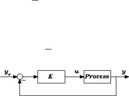
Figure 6: Ziegler-Nichols ultimate period method
In the ultimate sensitivity method the key idea is to determine the point where the Nyquist curve of the open loop system intersects the negative real axis. This is done by increasing the gain of a proportional controller in figure 6 until the closed loop system reaches the stability limit. The gain and the corresponding period ! of the oscillation are then determined and the PID coefficients are then found from Table 2.
In the step response method the unit step response of the process is determined experimentally (figure 3). It will be assumed that the step response is monotone except for a small initial part which eventually can have a non minimum phase characteristic. The tangent with the steepest slope and its intersection with the time axis are determined and the PID parameters are then obtained from table 3.
