

Piezo systems inc catalog.2005
.pdfPIEZO SYSTEMS, INC.
TRANSDUCER ELEMENTS
186 Massachusetts Avenue Cambridge, MA 02139 • Tel: (617) 547-1777 • Fax: (617) 354-2200 • Web: www.piezo.com • E-mail: sales@piezo.com
MOTOR PERFORMANCE
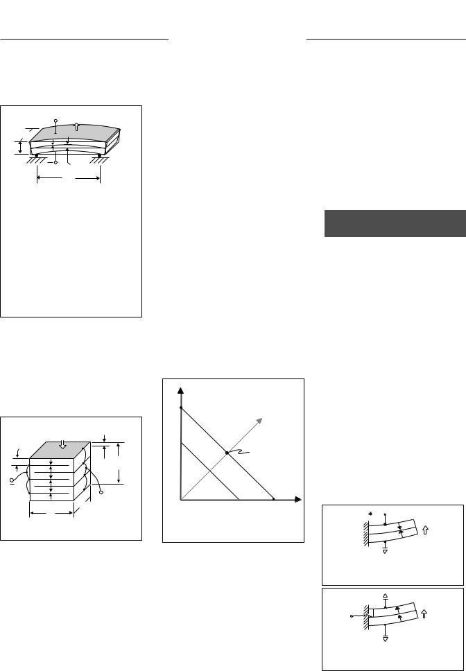
Piezoelectric actuators are usually specified in terms of their free deflection and blocked force. Free deflection (Xf) refers to displacement attained at the maximum recommended voltage level when the actuator is completely free to move and is not asked to exert any force. Blocked force (Fb) refers to the force exerted at the maximum recommended voltage level when the actuator is totally blocked and not allowed to move. Deflection is at a maximum when the force is zero, and force is at a maximum when the deflection is zero. All other values of simultaneous displacement and force are determined by a line drawn between these points on a force versus deflection line, as shown in Figure-6. Generally, a piezo motor must move a specified amount and exert a specified force, which determines its operating point on the force vs. deflection line. An actuator is considered optimized for a particular application if it delivers the required force at one half its free deflection. All other actuators satisfying the design criteria will be larger, heavier, and consume more power.
|
|
Direction of |
||
Fb |
|
increasing |
||
V |
voltage |
|||
|
||||
|
max |
|
|
|
|
> |
|
|
|
Force |
V |
optimized to |
||
V |
||||
|
1 |
Operating point |
||
|
|
|||
|
1 |
produce |
||
|
|
|||
|
|
maximum work |
||
|
|
Deflection |
Xf |
|
Figure-6. Force vs. displacement diagram for a piezo motor.
PIEZO GENERATORS (SENSORS)
Piezo generators convert force and motion to voltage and charge.
SINGLE LAYER GENERATORS
LONGITUDINAL AND TRANSVERSE
GENERATORS: When a mechanical stress is applied to a single sheet of piezoceramic in the longitudinal direction (parallel to polarization), a voltage is generated which tries to return the piece to its original thickness (Figure-7). Similarly, when a stress is applied to a sheet in a transverse direction (perpendicular to polarization), a voltage is generated which tries to return the piece to its original length and width (Figure-8). A piezo sheet bonded to a structural member which is stretched or flexed will induce electrical generation.
Vout + |
∆ Tin |
Fin |
|
|
T |
|
P |
|
W |
|
L |
Fig-7. Longitudinal (d33) Generator |
|
Fin |
|
T |
|
P |
|
|
|
|
∆ Lin |
Vout + |
W |
|
||
|
|
L |
Fig-8. Transverse (d31) Generator, |
||
|
Compressed on sides. |
|
2-LAYER GENERATORS
Applying a mechanical stress to a laminated two layer element results in electrical generation depending on the direction of the force, the direction of polarization, and the wiring of the individual layers.
EXTENSION GENERATORS: When
a mechanical stress causes both layers of a suitably polarized 2-layer element to stretch (or compress), a voltage is generated which tries to return the piece to its original dimension. Essentially, the element acts like a single sheet of piezo. The metal shim sandwiched between the two piezo layers provides mechanical strength and stiffness while shunting a small portion of the force (Figure-9).
Fin |
|
T |
|
|
P |
||
|
|
|
|
|
|
Vout + |
P |
∆ |
Lin |
W |
|
|
|
||
|
|
|
L |
For extension generators of the same thickness and force loading:
XL, |
Deflection Limit L |
|
|
|
Voc, |
Open Circuit Voltage |
XL |
/ |
L = 1 |
Icc, |
Closed Circuit Current |
|
L |
x W |
Fig-9. 2-Layer Transverse Generator,
Compressed lengthwise.
BENDING GENERATORS: When a
mechanical force causes a suitably polarized 2-layer element to bend, one layer is compressed and the other is stretched. Charge develops across each layer in an effort to counteract the imposed strains. This charge may be collected as observed in Figure-10a and 10b
|
Fin |
|
T |
|
|
|
∆ Xin |
|
Vout + |
W |
|
L |
||
|
For bending generators of the same thickness and force loading:
XL, |
Deflection Limit L2 |
|
Voc, |
Open Circuit Voltage |
XL / L2 = 1 |
Icc, Closed Circuit Current |
L x W |
|
Figure-10a. Bending Generator,
Cantilever Mount
21 |
CATALOG #6, 2005 |
TRANSDUCER ELEMENTS
PIEZO SYSTEMS, INC.
186 Massachusetts Avenue Cambridge, MA 02139 • Tel: (617) 547-1777 • Fax: (617) 354-2200 • Web: www.piezo.com • E-mail: sales@piezo.com
Vout + Fin
W
T
∆ Xin
L
To convert cantilever to simple beam generator performance (for the same thickness and force load):
Voc = 1/4X cantilever voltage
Icc = 1/4X cantilever current
To convert cantilever to simple beam performance (for the same thickness and deflection):
Voc = 4X cantilever voltage
Icc = 4X cantilever current
Figure-10b. Bending Generator,
Simple Beam Mount
MULTI-LAYER GENERATORS
STACK GENERATORS: The stack,
which comprises a large number of piezo layers, is a very stiff structure with a high capacitance. It is suitable for handling high force and collecting a large volume of charge.
∆ Tin |
Fin |
t |
T = n t |
P |
+Vout |
W |
L |
Figure-11. Stack Generator |
GENERATOR PERFORMANCE
For sinusoidal drive, piezoelectric generators may be specified in terms of their closed-circuit current and open-circuit voltage. Closed-circuit current, ICC, refers to the total current developed, at the maximum recommended strain level and operating frequency, when charge is completely free to travel from one electrode to the other, and is not asked to build up
voltage. Open-circuit voltage, Voc, refers to the voltage developed at the maximum recommended strain level, when charge is prohibited from traveling from one electrode to the other. Current is at a maximum when the voltage is zero, and voltage is at a maximum when the charge transfer is zero. All other values of simultaneous current and voltage levels are determined by a line drawn between these points on a voltage versus current line, as shown in Figure-12. Generally, a piezo generator must deliver a specified current and voltage, which determines its operating point on the voltage vs. current line. Maximum power extraction for a particular application occurs when the generator delivers the required voltage at one half its closed circuit current. All other generators satisfying the design criteria will be larger, heavier, and require more power input.
|
|
Direction of |
|
Voc |
|
increasing |
|
|
strain |
||
|
S |
||
|
max |
|
|
|
> |
|
|
Voltage |
S |
|
|
1 |
Operating point |
||
S |
|||
optimized to |
|||
1 |
|||
|
produce |
||
|
|
||
|
|
maximum work |
|
|
Current |
Icc |
|
Figure-12. Voltage vs. current |
|||
diagram for a piezo generator. |
|||
STATIC & DYNAMIC OPERATION
As a sensor or force gauge, piezo elements are excellent for handling dynamic and transient inputs, but poor at measuring static inputs.This is due to charge leakage between electrodes and into monitoring circuits.
Piezoceramic may be used as a strain gauge for easy and rapid determina-
tion of dynamic strains in structures. They exhibit extremely high signal/noise ratios, on the order of 50 times that of wire strain gauges, and are small enough that on most structures they will not materially affect the vibrational characteristics of the structure.
SERIES & PARALLEL
OPERATION
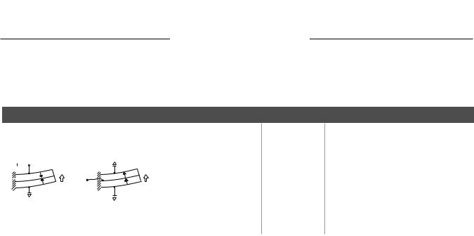
For motors, series operation refers to the case where supply voltage is applied across all piezo layers at once. The voltage on any individual layer is the supply voltage divided by the total number of layers. A 2-layer device wired for series operation uses only two wires (Figure-13), one attached to each outside electrode.
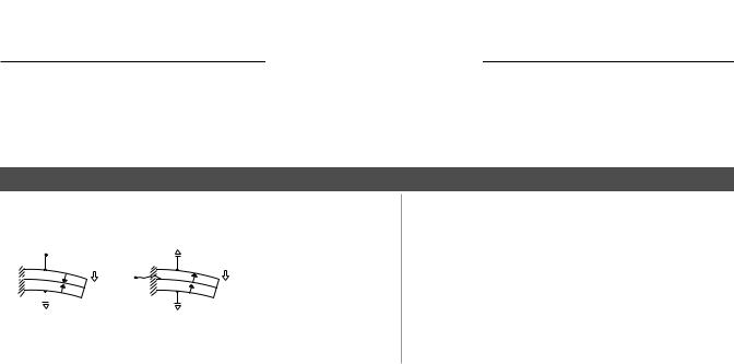
Parallel operation refers to the case where the supply voltage is applied to each piezo layer individually. This means accessing and attaching wires to each layer. A 2-layer bending motor wired for parallel operation requires three wires (Figure-14), one attached to each outside electrode and one attached to the center shim. For the same motion, a 2-layer motor poled for parallel operation needs only half the voltage required for series operation and has four times the capacitance.
Vin |
∆ Xout |
|
∆ Fout |
Figure-13. A 2-Layer Bending Motor Poled for Series Operation (2-wire)
∆ Xout
∆ Fout
 Vin
Vin
Figure-14. A 2-Layer Bending Motor Poled for Parallel Operation (3-wire)
CATALOG #6, 2005 |
22 |

PIEZO SYSTEMS, INC.
SINGLE LAYER ELEMENTS
186 Massachusetts Avenue |
Cambridge, MA 02139 • Tel: (617) 547-1777 • |
Fax: (617) 354-2200 • |
Web: www.piezo.com • E-mail: |
sales@piezo.com |
|||||||||||||||||||||
|
|
|
|
|
PSI-5A4E PIEZOELECTRIC SINGLE SHEET |
|
|
||||||||||||||||||
|
|
|
|
|
|
|
|
|
|
|
|
|
|
|
|
|
|
|
|
|
|
||||
|
|
|
|
|
|
|
|
|
|
|
|
|
|
|
|
|
|
PART NUMBER |
THICKNESS |
CAPACITANCE |
|
||||
|
|
|
|
|
|
|
|
|
|
|
|
|
|
|
|||||||||||
|
|
|
|
|
|
|
|
|
|
|
|
|
|
|
|
|
|
|
|
|
|
|
|
|
|
|
|
|
|
|
|
|
|
|
|
|
|
|
|
|
|
|
|
|
|
|
|
mm |
nF |
(±10%) |
|
|
|
|
|
|
|
|
|
|
|
|
|
|
|
|
|
|
|
|
|
|
|
|
|
||
|
|
|
|
|
|
|
|
|
|
|
|
|
|
|
|
|
|
T105-A4E-602 |
|
.127 |
|
650 |
|
||
|
|
|
|
|
|
|
|
|
|
|
|
|
|
|
|
|
|
T107-A4E-602 |
|
.191 |
|
430 |
|
||
|
|
|
|
|
|
|
|
|
|
|
|
|
|
|
|
|
|
T110-A4E-602 |
|
.267 |
|
315 |
|
||
|
|
|
|
|
|
|
|
|
|
|
|
|
|
|
|
|
|
T120-A4E-602 |
|
.508 |
|
162 |
|
||
2.85 |
|
|
|
|
Nickel electrodes |
|
|
|
|
|
|
|
|
T140-A4E-602 |
|
1.02 |
|
80 |
|
||||||
|
|
|
|
|
|
|
|
|
|
|
|
T180-A4E-602 |
|
2.03 |
|
40 |
|
||||||||
(72.4) |
|
|
|
|
both sides |
|
|
|
|
|
|
|
|
|
|
|
|||||||||
|
|
|
|
|
|
|
|
|
|
|
|
|
|
|
|
|
|
|
|
||||||
|
|
|
|
|
|
|
|
|
.005 |
± .0005 |
(.127 |
± .013) |
|
|
|
||||||||||
|
|
|
|
|
|
|
|
|
|
|
|
|
|
|
|
|
|
||||||||
|
|
|
|
|
|
|
|
|
|
|
|
|
|
|
|
|
|
||||||||
|
|
|
|
|
|
|
|
|
|
|
|
|
|
|
.0075 |
± .0005 |
(.191 |
± .013) |
|
|
|
||||
|
|
|
|
|
|
|
|
|
|
|
|
|
|
|
.0105 |
± .0005 |
(.267 |
± .013) |
|
|
|
||||
|
|
|
|
|
|
|
|
|
|
|
|
|
|
|
.020 |
± .0005 |
(.508 |
± .013) |
|
|
|
||||
|
|
|
|
|
|
|
|
|
|
|
|
|
|
|
.040 |
± .0010 (1.016 ± .025) |
|
|
|
||||||
|
|
|
|
|
|
|
|
|
|
|
|
|
|
|
|
|
|
||||||||
|
|
|
|
|
|
|
|
|
|
|
|
|
|
|
|
|
|
||||||||
|
|
|
|
|
|
|
2.85 (72.4) |
|
|
|
|
|
|
|
|
|
.080 |
± .0020 (2.032 ± .050) |
|
|
|
||||
|
|
|
|
|
|
|
|
|
|
|
|
|
|
|
|
|
|
||||||||
|
|
|
|
|
|
|
|
|
|
|
|
|
|
|
|
|
|
|
|
|
|
|
|
|
|
PIEZOELECTRIC AND MATERIAL PROPERTIES
PIEZOELECTRIC SINGLE SHEET
PIEZOELECTRIC |
|
|
|
|
|
|
|
|
|
Composition |
|
|
Lead Zirconate Titanate |
|
|
||
|
Piezo Systems Material Designation |
|
Type 5A4E |
(Industry Type 5A, Navy Type II) |
||||
|
Relative Dielectric Constant (@1KHz) |
KT3 |
1800 |
|
|
|
||
|
Piezoelectric Strain Coefficient |
|
d33 |
390 x 10-12 |
meters/Volt |
|
||
|
|
|
|
d31 |
-190 x 10-12 |
meters/Volt |
|
|
|
Piezoelectric Voltage Coefficient |
|
g33 |
24.0 x 10⁻³ |
Volt meters/Newton |
|
||
|
|
|
|
g31 |
-11.6 x 10⁻³ |
Volt meters/Newton |
|
|
|
Coupling Coefficient |
|
k33 |
0.72 |
|
|
|
|
|
Polarization Field |
|
k31 |
0.35 |
Volts/meter |
|
||
|
|
Ep |
2 x 10⁶ |
|
||||
|
Initial Depolarization Field |
|
Ec |
5 x 10⁵ |
Volts/meter |
|
||
MECHANICAL |
|
|
ρ |
|
|
|
|
|
|
Density |
|
|
7800 |
Kg/meter3 |
|
|
|
|
Mechanical Q |
|
|
80 |
|
|
|
|
|
Elastic Modulus |
|
YE3 |
5.2 x 10¹⁰ |
Newtons/meter2 |
|
||
THERMAL |
|
|
YE1 |
6.6 x 10¹⁰ |
Newtons/meter2 |
|
||
|
|
|
~4 x 10⁻⁶ |
|
|
|
||
|
Thermal Expansion Coefficient |
|
|
meters/meter °C |
|
|||
|
Curie Temperature |
|
|
350 |
°C |
|
|
|
|
|
|
|
|
|
|||
|
|
|
|
|
|
|
|
|
ORDERING INFORMATION |
PART NO. |
1 pc. |
5 pc. |
25 pc. |
100 pc. |
|||
PSI-5A4E |
(2.85” Square x |
.005”T) |
T105-A4E-602 |
$100 |
$70 |
$50 |
$35 |
|
PSI-5A4E |
(2.85” Square x |
.0075”T) |
T107-A4E-602 |
$100 |
$60 |
$40 |
$30 |
|
PSI-5A4E |
(2.85” Square x |
.0105”T) |
T110-A4E-602 |
$100 |
$70 |
$50 |
$35 |
|
PSI-5A4E |
(2.85” Square x |
.020”T) |
T120-A4E-602 |
$125 |
$90 |
$70 |
$60 |
|
PSI-5A4E |
(2.85” Square x |
.040”T) |
T140-A4E-602 |
$150 |
$120 |
$90 |
$80 |
|
PSI-5A4E |
(2.85” Square x |
.080”T) |
T180-A4E-602 |
$200 |
$160 |
$120 |
$110 |
|
updated pricing in blue, 8/2005
23 |
CATALOG #6, 2005 |
PIEZO SYSTEMS, INC.
SINGLE LAYER ELEMENTS
186 Massachusetts Avenue Cambridge, MA 02139 • Tel: (617) 547-1777 • Fax: (617) 354-2200 • Web: www.piezo.com • E-mail: sales@piezo.com
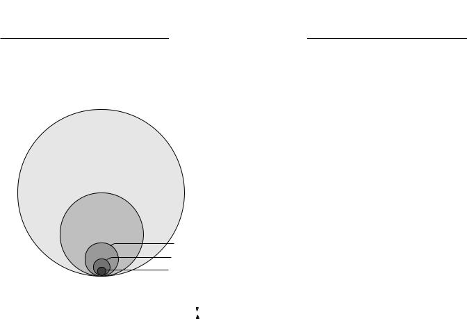
PSI-5A4E SINGLE LAYER DISK ELEMENTS
|
|
|
|
|
.0075” (.191M M ) |
TH I C K |
|
|
|
|
|
|
||||||||
|
|
|
|
|
|
|
|
|
|
|
|
|
|
|
|
|
|
|||
|
|
|
|
|
|
|
|
|
|
|
|
PART NUMBER |
|
DIAMETER |
|
CAPACITANCE |
|
|||
|
|
|
|
|
|
|
|
|
|
|
|
|
|
|
|
|
|
|
|
|
|
|
|
T107-A4E-573 |
|
|
|
|
inches |
mm |
|
nF |
(±10%) |
|
|||||||
|
|
|
|
|
T107-A4E-073 |
|
.125 |
3.2 |
|
|
.65 |
|
||||||||
|
|
|
|
|
|
|
|
|
|
|
|
|
|
|
|
|||||
|
|
|
|
|
|
|
|
|
|
|
|
T107-A4E-173 |
|
.250 |
6.4 |
|
|
2.7 |
|
|
|
|
|
|
|
|
|
|
|
|
|
|
T107-A4E-273 |
|
.500 |
12.7 |
|
|
10.6 |
|
|
|
|
|
|
|
|
|
|
|
|
|
|
T107-A4E-373 |
|
1.25 |
31.8 |
|
|
66.4 |
|
|
|
|
|
|
|
|
|
|
|
|
|
|
T107-A4E-573 |
|
2.50 |
63.5 |
|
|
265 |
|
|
|
|
|
T107-A4E-373 |
|
|
|
|
|
|
|
|
|
|
|
||||||
|
|
|
|
|
|
|
|
|
|
|
|
|
|
|||||||
|
|
|
|
|
T107-A4E-273 |
|
|
|
|
|
|
|
|
|
|
|||||
|
|
|
|
|
T107-A4E-173 |
|
|
|
|
|
|
|
|
|
|
|||||
|
|
|
|
|
T107-A4E-073 |
|
|
|
|
|
|
|
|
|
|
|||||
|
|
|
Top View (Scale: x1) |
|
|
|
|
|
|
|
|
|
|
|
||||||
|
|
|
|
|
|
|
|
|
|
.0075" |
(.191) |
|
|
|
|
|
|
|
|
|
|
|
|
|
|
|
|
|
|
|
|
|
|
|
|
|
|
|
|||
|
|
|
|
|
|
|
|
|
|
|
|
|
|
|
|
|
|
|||
|
|
|
|
|
|
|
|
|
|
|
|
|
|
|
|
|
|
|||
|
|
|
|
|
|
|
|
|
|
|
|
|
|
|
|
|||||
|
|
|
|
|
|
|
|
|
|
|
|
|
|
|
|
|
|
|
|
|
|
|
|
|
|
|
|
|
|
|
|
|
|
|
|
|
|
|
|
|
|
|
|
|
PIEZOELECTRIC AND MATERIAL PROPERTIES |
|
|
|
|
|||||||||||||
|
|
|
|
|
|
|
|
|
|
|
|
|
|
|
|
|
|
|
||
|
|
|
|
|
PIEZOELECTRIC SINGLE SHEET |
|
|
|
|
|
|
|||||||||
|
|
PIEZOELECTRIC |
|
|
|
|
|
|
|
|||||||||||
|
|
|
|
|
|
|
|
|
|
|
|
|
|
|
|
|
|
|
||
|
|
|
|
|
|
|
|
|
|
|
|
|
|
|
|
|
|
|
||
|
|
|
Composition |
|
|
|
Lead Zirconate Titanate |
|
|
|
|
|||||||||
|
|
|
Piezo Systems Material Designation |
|
|
PSI 5A4E (Industry Type 5A, Navy Type II) |
||||||||||||||
|
|
|
Relative Dielectric Constant (@1KHz) |
|
KT3 |
1800 |
|
meters/Volt |
|
|
||||||||||
|
|
|
Piezoelectric Strain Coefficient |
|
|
d |
390 x 10-12 |
|
|
|||||||||||
|
|
|
|
|
|
|
|
|
|
|
33 |
|
|
|
|
|
|
|
|
|
|
|
|
Piezoelectric Voltage Coefficient |
|
|
d31 |
-190 x 10-12 |
meters/Volt |
|
|
||||||||||
|
|
|
|
|
g |
24.0 x 10⁻³ |
Volt meters/Newton |
|||||||||||||
|
|
|
|
|
|
|
|
|
|
|
33 |
-11.6 x 10⁻³ |
Volt meters/Newton |
|||||||
|
|
|
|
|
|
|
|
|
|
|
|
g |
||||||||
|
|
|
|
|
|
|
|
|
|
|
31 |
|
|
|
|
|
|
|
|
|
|
|
|
Coupling Coefficient |
|
|
k33 |
0.72 |
|
|
|
|
|
|
|
||||||
|
|
|
Polarization Field |
|
|
k31 |
0.32 |
|
Volts/meter |
|
|
|||||||||
|
|
|
|
|
Ep |
2 x 10⁶ |
|
|
||||||||||||
|
|
|
Initial Depolarization Field |
|
|
Ec |
5 x 10⁵ |
Volts/meter |
|
|
||||||||||
|
|
MECHANICAL |
|
|
|
|
|
|
|
|
ρ |
|
|
|
|
|
|
|
|
|
|
|
|
Density |
|
|
|
|
|
|
|
|
7800 |
|
Kg/meter3 |
|
|
|
|
||
|
|
|
Mechanical Q |
|
|
|
80 |
|
|
|
|
|
|
|
||||||
|
|
|
Elastic Modulus |
|
|
YE3 |
5.2 x 10¹⁰ |
Newtons/meter2 |
|
|
||||||||||
|
|
THERMAL |
|
|
|
|
|
|
|
|
YE1 |
6.6 x 10¹⁰ |
Newtons/meter2 |
|
|
|||||
|
|
|
|
|
|
|
|
|
|
|
~4 x 10⁻⁶ |
|
|
|
|
|
|
|||
|
|
|
Thermal Expansion Coefficient |
|
|
|
meters/meter °C |
|
|
|||||||||||
|
|
|
Curie Temperature |
|
|
|
350 |
|
°C |
|
|
|
|
|
||||||
|
|
|
|
|
|
|
|
|
|
|
|
|
|
|
|
|
||||
|
|
|
|
|
|
|
|
|
|
|
|
|
|
|
|
|
|
|
|
|
ORDERING INFORMATION |
PART NO. |
1 pc. |
5 pc. |
25 pc. |
100 pc. |
|||||||||||||||
PSI-5A4E |
(.125” Diameter x |
.0075”T) |
T107-A4E-073 |
$75 |
|
$30 |
|
$12 |
$4 |
|
||||||||||
PSI-5A4E |
(.250” Diameter x |
.0075”T) |
T107-A4E-173 |
$75 |
|
$40 |
|
$16 |
$6 |
|
||||||||||
PSI-5A4E |
(.500” Diameter x |
.0075”T) |
T107-A4E-273 |
$75 |
|
$50 |
|
$20 |
$10 |
|
||||||||||
PSI-5A4E |
(1.25” Diameter x |
.0075”T) |
T107-A4E-373 |
$100 |
|
$65 |
|
$40 |
$29 |
|
||||||||||
PSI-5A4E |
(2.50” Diameter x |
.0075”T) |
T107-A4E-573 |
$175 |
|
$149 |
|
$119 |
$99 |
|
||||||||||
CATALOG #6, 2005 |
24 |
SINGLE LAYER ELEMENTS
PIEZO SYSTEMS, INC.
186 Massachusetts Avenue Cambridge, MA 02139 • Tel: (617) 547-1777 • Fax: (617) 354-2200 • Web: www.piezo.com • E-mail: sales@piezo.com
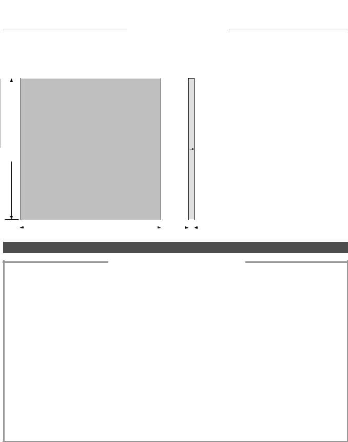
PSI-5H4E PIEZOELECTRIC SINGLE SHEET
|
|
|
|
|
|
Nickel electrodes |
|
|
|
|
|
|
|
2.85 |
|
|
|
|||
|
||||||
(72.4) |
|
|
|
both sides |
||
PART NUMBER |
THICKNESS |
CAPACITANCE |
|
|
|
|
mm |
nF (±10%) |
|
|
|
T105-H4E-602 |
.127 |
1250 |
T107-H4E-602 |
.191 |
850 |
T110-H4E-602 |
.267 |
610 |
|
|
|
|
|
|
|
|
.005 |
± .0005 |
(.127 |
± .013) |
|||||||
|
|
|
|
|
|
|
|
|
|
.0075 |
± .0005 |
(.191 |
± .013) |
||
|
|
2.85 (72.4) |
|
|
|
|
|||||||||
|
|
|
|
|
|
|
|
|
|
.0105 |
± .0005 |
(.267 |
± .013) |
||
|
|
|
|
|
|
|
|
|
|||||||
|
|
|
|
|
|
|
|
|
|
|
|
|
|
|
|
PIEZOELECTRIC AND MATERIAL PROPERTIES
PIEZOELECTRIC SINGLE SHEET
PIEZOELECTRIC |
|
|
|
Composition |
|
Lead Zirconate Titanate |
|
Piezo Systems Material Designation |
|
Type 5H4E |
(Industry Type 5H, Navy Type VI) |
Relative Dielectric Constant (@1KHz) |
KT3 |
3800 |
meters/Volt |
Piezoelectric Strain Coefficient |
d |
650 x 10-12 |
|
|
33 |
|
|
|
d31 |
-320 x 10-12 |
meters/Volt |
Piezoelectric Voltage Coefficient |
g33 |
19.0 x 10⁻³ |
Volt meters/Newton |
|
g31 |
-9.5 x 10⁻³ |
Volt meters/Newton |
Coupling Coefficient |
k33 |
.75 |
|
Polarization Field |
k31 |
.44 |
Volts/meter |
Ep |
1.5 x 10⁶ |
||
Initial Depolarization Field |
Ec |
3.0 x 10⁵ |
Volts/meter |
MECHANICAL |
ρ |
|
|
Density |
7800 |
Kg/meter3 |
|
Mechanical Q |
|
32 |
|
Elastic Modulus |
YE3 |
5.0 x 10¹⁰ |
Newtons/meter2 |
|
YE1 |
6.2 x 10¹⁰ |
Newtons/meter2 |
THERMAL |
|
|
|
Thermal Expansion Coefficient |
|
~3 x 10⁻⁶ |
meters/meter °C |
Curie Temperature |
|
230 |
°C |
ORDERING INFORMATION |
PART NO. |
1 pc. |
5 pc. |
25 pc. |
100 pc. |
||
PSI-5H4E |
(2.85” Square x |
.005”T) |
T105-H4E-602 |
$100 |
$70 |
$50 |
$35 |
PSI-5H4E |
(2.85” Square x |
.0075”T) |
T107-H4E-602 |
$100 |
$60 |
$40 |
$30 |
PSI-5H4E |
(2.85” Square x |
.0105”T) |
T110-H4E-602 |
$100 |
$70 |
$50 |
$35 |
CATALOG #6, 2005 |
25 |
PIEZO SYSTEMS, INC.
2-PIEZO LAYER ELEMENTS
186 Massachusetts Avenue Cambridge, MA 02139 • Phone: (617) 547-1777 • Fax: (617) 354-2200 • Web: www.piezo.com • E-mail: sales@piezo.com
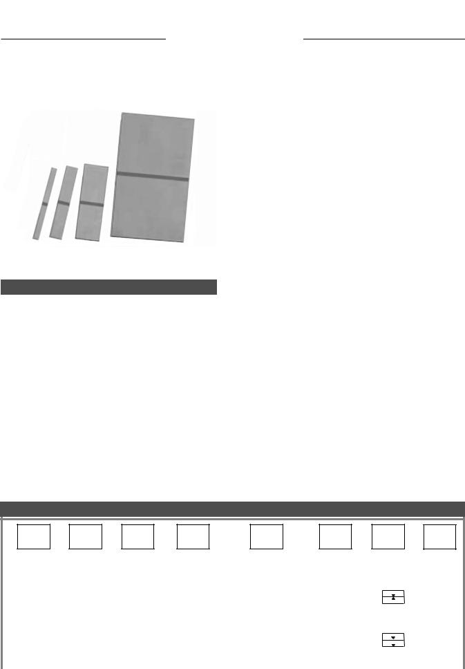
2-PIEZO LAYER TRANSDUCERS - BENDERS & EXTENDERS
US E D A S MOTO R S (AC T UATO R S ) A N D GE N E R ATO R S (S E N S O R S )
|
|
|
|
|
|
|
|
|
|
-103 |
|
-203 |
|
-303 |
|
-503 Size |
|
|
|
|
|
|
|
|
|
|
|
|
|
|
|
|
|
|
|
DESCRIPTION
Piezo Systems specializes in the manufacture of 2-piezo layer bending and extending elements, and offers a wide selection from which to choose. It is important to note that the same 2-layer transducer can be used as either a bending motor, a bending generator, an extending motor or an extending generator. Part numbers pertain to geometry and construction rather than usage.
Mounting Options: Transducer elements with a part number starting with T consist of the transducer alone. Pre-mount- ed and wired elements are discussed on pages 37-46.
Reinforcement Material: Typically, the center shim reinforcement material has little effect on performance. Rather, it enhances other properies such as strength, thermal range, and magnetism.
Size: Larger elements (greater piezo volume) produce greater output energy.
TRANSDUCER PART NUMBERS
Polarization: 2-piezo layer elements may have their layers poled in the same direction (Y-poled), or in opposite directions (X-poled). Polarization and wiring determine whether the element layers will be operate in serial or parallel mode (see page 22). In parallel mode, the user must access the center layer and attach a third wire.
Performance: The performance data for -103, -203, and -303 size transducers is based on a 1.0” active length. The performance data for -503 size transducers is a 2.0” active length.
Example 1: T220-A4-503X
This is an unmounted 2-piezo layer element, made with PSI5A4E piezoceramic (nickel electrodes) and a brass center shim reinforcement. It is 2.50” long, 1.25” wide, .020” thick, and is X-poled. It may be used as:
■a bending motor poled for 2-wire series operation,
■a bending generator poled for 2-wire series operation,
■an extension motor poled for 3-wire parallel operation,
■an extension generator poled for 3-wire parallel operation.
Example 2: T220-A3NM-303Y
This is an unmounted 2-piezo layer transducer, made with PSI-5A3 piezoceramic (silver electrodes) and a non-magnet- ic center shim. It is 1.250” long, 0.50” wide, .020” thick, and is Y-poled. It may be used as:
■a non-magnetic bending motor poled for 3-wire parallel operation,
■a non-magnetic bending generator poled for 3-wire parallel operation,
■a non-magnetic extension motor poled for 2-wire series operation,
■a non-magnetic extension generator poled for 2-wire series operation.
OPTIONS LISTED IN COLUMNS UNDER HEADINGS
T |
2 |
20 |
- |
A4 |
- |
503 |
X |
|
|
|
|
|
|
|
|
|
|
|
|
|
|
|
|
|
|
|
|
|
|
|
|
|
|
|
|
|
|
|
|
|
MOUNTING |
|
|
NUMBER OF |
|
|
THICKNESS |
|
|
|
PIEZOCERAMIC |
|
|
|
REINFORCEMENT |
|
|
SIZE |
|
|
|
POLARIZATION |
|
|
INTENDED |
|
|||||
|
STYLES |
|
|
PIEZO LAYERS |
|
|
DESIGNATION |
|
|
|
MATERIALS |
|
|
|
MATERIALS |
|
|
DESIGNATION |
|
|
|
|
|
|
|
USE |
|
||||
|
|
|
|
|
|
|
|
|
|
|
|
|
|
|
|
|
|
|
|
|
|
|
|
|
|
|
|
|
|
|
|
|
|
|
|
|
|
|
|
|
|
|
|
|
|
|
|
|
|
|
|
|
|
|
|
|
|
|
|
|
|
|
|
|
|
|
|
|
|
|
|
|
|
|
|
|
|
|
|
|
|
|
|
|
|
|
|
|
|
|
|
|
|||
|
T - Transducer |
|
|
2 |
|
|
15 |
(.015”) |
|
|
|
-A4 PSI-5A4E |
|
|
|
(blank) - Standard |
|
|
-103 |
|
|
|
|
|
|
|
Not used |
||||
|
|
|
|
|
|
|
|
|
|
|
|
|
|
|
|
|
|
||||||||||||||
|
|
|
|
|
|
|
|
|
|
|
|
|
|
|
|
|
|
||||||||||||||
|
Only |
|
|
|
|
|
16 |
(.016”) |
|
|
|
|
-H4 PSI-5H4E |
|
|
|
Brass Shim |
|
|
-203 |
|
|
|
|
|
|
|
for |
|
||
|
|
|
|
|
|
|
|
|
|
|
|
|
|
|
|
|
|
|
|||||||||||||
|
|
|
|
|
|
|
|
|
|
|
|
|
|
|
|
|
|
|
|||||||||||||
|
|
|
|
|
|
|
|
|
|
|
|
|
|
|
|
|
SS - High Strength |
|
|
|
|
|
|
|
|
|
|
|
|
|
|
|
|
|
|
|
|
|
19 |
(.019”) |
|
|
|
|
|
-303 |
|
|
|
X-Poled |
|
|
Transducer |
|
|||||||||
|
No Mount |
|
|
|
|
|
20 |
(.020”) |
|
|
|
|
-A3 PSI-5A3 |
|
|
|
Stainless Steel |
|
|
-503 |
|
|
|
|
|
|
|
Elements |
|
|
|
|
|
|
|
|
|
|
|
|
|
|
|
|
|
|
|
|
|
|
|||||||||||||
|
|
|
|
|
|
|
|
|
|
|
|
|
NM - Non-magnetic |
|
|
|
|
|
|
|
|
|
|
|
|||||||
|
NoWires |
|
|
|
|
|
23 |
(.023”) |
|
|
|
|
|
|
|
|
|
|
|
|
|
|
|
|
|
|
|
|
|
||
|
|
|
|
|
|
|
|
|
|
|
|
|
|
CL - High |
|
|
|
|
|
|
|
|
|
|
|
|
|
||||
|
|
|
|
|
|
|
|
|
|
|
|
|
|
|
|
|
|
|
|
|
|
|
|
|
|||||||
|
|
|
|
|
|
|
|
|
|
|
|
|
|
|
|
|
|
|
|
|
|
|
|
|
|||||||
|
|
|
|
|
|
|
26 |
(.026”) |
|
|
|
|
|
|
|
|
Performance |
|
|
|
|
|
|
|
|
|
|
|
|
|
|
|
|
|
|
|
|
|
|
|
|
|
|
|
|
|
|
|
|
|
|
|
|
|
|
|
|
||||||
|
|
|
|
|
|
|
|
|
|
|
|
|
|
|
|
|
|
|
|
|
|
|
|
|
|
||||||
|
|
|
|
|
|
|
|
|
|
|
|
|
|
|
|
Y-Poled |
|
|
|
|
|
||||||||||
|
|
|
|
|
|
|
34 |
(.034”) |
|
|
|
|
|
|
|
|
NO - No shim |
|
|
|
|
|
|
|
|
|
|
|
|||
|
|
|
|
|
|
|
|
|
|
|
|
|
|
|
|
|
|
|
|
|
|
|
|
|
|
|
|
|
|
|
|
|
|
|
|
|
|
|
|
|
|
|
|
|
|
|
|
|
|
|
|
|
|
|
|
|
|
|
|
|
|
|
|
26 |
CATALOG #6, 2005 |

2-PIEZO LAYER ELEMENTS
PIEZO SYSTEMS, INC.
186 Massachusetts Avenue Cambridge, MA 02139 • Tel: (617) 547-1777 • Fax: (617) 354-2200 • Web: www.piezo.com • E-mail: sales@piezo.com
2-PIEZO LAYER TRANSDUCERS - BENDERS & EXTENDERS
US E D A S MOTO R S A N D GE N E R ATO R S
PIEZO MATERIALS
|
|
|
|
|
|
|
|
|
|
|
|
|
|
PIEZOCERAMIC |
|
|
DESCRIPTION |
|
|
||||
|
|
MATERIAL |
|
|
|
|
|
|
|
|
|
|
|
|
|
|
|
|
|
|
|
|
|
|
|
|
|
|
|
|
|
|
|
|
|
|
|
|
|
|
PSI-5A4E is an industry type 5A (Navy Type II) piezoceramic (see page 23). Thin vacuum sputtered nickel |
|
|||||
|
|
A4 |
|
electrodes produce extremely low current leakage and low magnetic permeability. It operates over a wide |
|
|
|||||
|
|
|
|
|
temperature range and is relatively temperature insensitive (see page 57). |
|
|
||||
|
|
|
|
|
|
|
|
|
|
|
|
|
|
|
|
|
|
|
|
|
|||
|
|
|
|
|
|
PSI-5H4E is an industry type 5H (Navy Type VI) piezoceramic (see page 25). It has a high motion/volt |
|
||||
|
|
|
|
|
|
and charge/newton rating, which is useful when voltage or force is limited. Thin vacuum sputtered nickel |
|
|
|||
|
|
H4 |
|
|
|
electrodes produce extremely low current leakage and magnetic permeability. However, its temperature |
|
|
|
|
|
|
|
|
|
|
|
|
|
||||
|
|
|
|
|
|
range is limited and its properties are more sensitive to temperature (See page 57). |
|
|
|
|
|
|
|
|
|
|
|
|
|
|
|
||
|
|
|
|
|
|
|
|
|
|
||
|
|
|
|
|
|
PSI-5A3 is an industry type 5A (Navy Type II) piezoceramic. Its has totally non-magnetic, fired-on silver |
|
||||
|
|
A3 |
|
|
|
|
|
|
|
||
|
|
|
|
|
electrodes, operates over a wide temperature range, and is relatively temperature insensitive. |
|
|
|
|
||
|
|
|
|
|
|
|
|
||||
|
|
|
|
|
|
|
|
|
|
|
|
|
|
|
|
|
|
|
|
|
|
|
|
STANDARD TRANSDUCER THICKNESSES
Electrode (nickel or silver)
TCERAMIC
PSI-5A4E, PSI-5H4E, or PSI-5A3 piezoceramic
P
Bond layer
PReinforcement material
(brass, stainless steel, non-magnetic, high performance, none)
TTOTAL
Polarization (shown as X poled)
THICKNESS |
TTOTAL |
TCERAMIC |
||
DESIGNATION |
Inches |
(mm) |
Inches (mm) |
|
15 |
.015 |
(.38) |
.005 |
(.13) |
16 |
.016 |
(.39) |
.0075 |
(.19) |
19 |
.019 |
(.48) |
.0075 |
(.19) |
20 |
.020 |
(.51) |
.0075 |
(.19) |
23 |
.023 |
(.58) |
.0075 |
(.19) |
26 |
.026 |
(.66) |
.0105 |
(.27) |
34 |
.034 |
(.86) |
.0105 |
(.27) |
|
|
|
|
|
STANDARD TRANSDUCER SIZES (L X W)
SIZE |
WIDTH |
LENGTH |
|
|
|
|
1.250 (31.8) |
|
|
|
|
|
|
|
|
|
|
|
|
|
|
||
|
|
|
|
|
|
|
|
|
|
|
|
|
|
|
|
|
|||||||
|
|
|
|
|
|
|
|
|
|
|
|
|
|
|
|||||||||
DESIGNATION |
|
|
|
|
|
|
|
|
|
|
|
|
|
|
|
|
|
|
|
|
|
|
|
Inches |
(mm) |
Inches |
(mm) |
|
|
|
-103 |
|
|
|
|
|
|
|
|
(3.2) |
|
|
|
|
|||
|
|
|
|
|
.125 |
|
|
|
|
||||||||||||||
|
|
|
|
|
|
|
|
||||||||||||||||
|
|
|
|
|
|
|
|
||||||||||||||||
|
|
|
|
|
|
|
|
|
|
|
|
|
|
|
|||||||||
|
|
|
|
|
|
|
|
|
|
|
|
|
|
|
|
|
|
|
|
|
|
|
|
-103 |
.125 |
(3.2) |
1.250 |
(31.8) |
|
|
|
-203 |
|
|
|
|
.250 |
(6.4) |
|
|
|
|
|||||
|
|
|
|
|
|
|
|||||||||||||||||
-203 |
.250 |
(6.4) |
1.250 |
(31.8) |
|
|
|
|
|
|
|
|
|
|
|
|
|
|
|
|
|
|
|
|
|
|
|
|
|
|
|
|
|
|
|
|
|
|
|
|
|
||||||
|
|
|
|
|
|
|
|
|
|
|
|
|
|
|
|
|
|
||||||
-303 |
.500 |
(12.7) |
1.250 |
(31.8) |
|
|
|
|
|
|
|
|
|
|
|
|
|
|
|
||||
|
|
-303 |
|
|
.500 (12.7) |
|
|
|
|
||||||||||||||
-503 |
1.250 |
(31.8) |
2.500 |
(63.5) |
|
|
|
|
|
|
|
|
|
|
|
|
|
|
|
|
|
|
|
|
|
|
|
|
|
|
|
|
|
|
|
|
|
|
|
|
|
||||||
|
|
|
|
|
|
|
|
|
|
|
|
|
|
|
|
|
|
|
|
|
|
|
|
|
|
|
|
|
|
|
|
-503 |
|
|
|
|
|
|
|
|
|
|
|
|
|
|
|
|
|
|
|
|
|
|
|
|
|
|
|
|
|
|
|
|
|
|
|
|
|
||
|
|
|
|
|
|
|
|
|
|
|
|
|
|
|
|
|
|
|
|
|
|
|
|
|
|
|
|
|
|
|
|
|
|
|
|
|
|
|
|
|
|
|
|
1.250 |
|||
|
|
|
|
|
|
W |
|
|
|
|
|
|
|
|
|
|
|
|
|||||
|
|
|
|
|
|
|
|
|
|
|
|
|
|
|
|
|
|
(31.8) |
|||||
|
|
|
|
|
|
|
|
|
|
|
|
|
|
|
|
|
|
|
|
||||
|
|
|
|
|
|
|
|
|
|
|
|
|
|
|
|
|
|
|
|
|
|
|
|
|
|
|
|
|
|
|
|
|
|
|
|
|
|
|
|
|
|
|
|
|
|
|
|
|
|
|
|
|
|
|
|
|
|
|
|
|
|
|
|
|
|
|
|
|
|
|
|
2.500 (63.5)
L
CATALOG #6, 2005 |
27 |
PIEZO SYSTEMS, INC.
2-PIEZO LAYER ELEMENTS
186 Massachusetts Avenue Cambridge , MA 02139 • Phone: (617) 547-1777 • Fax: (617) 354-2200 • Web: www.piezo.com • E-mail: sales@piezo.com
2-PIEZO LAYER BENDING MOTORS
STA N DA R D - BR A S S RE I N F O R C E D
PERFORMANCE: BRASS SHIM BENDING MOTORS (Cantilever Mount)
VALUES TO BE USED AS GUIDELINES
|
|
|
PART NUMBERS |
|
|
|
|
|
|
|
|
|
|
|
|
|
|
|
|
|
|
|
|
|
|
|
|
|
|
|
|
||||||||
|
|
|
|
|
|
|
|
|
|
|
|
|
|
|
|
|
|
|
|
|
|
|
|
|
|
|
|
|
|
|
|||||||||
|
|
|
|
|
|
|
|
|
|
|
|
|
|
|
|
|
|
|
|
|
|
|
|
|
|
|
|
|
|
|
|||||||||
|
|
|
(BRASS REINFORCED BENDER) |
|
|
|
|
|
|
|
|
|
|
|
|
|
|
|
|
|
|
|
|
|
|
|
|
|
|
|
|
||||||||
|
|
|
|
|
|
|
|
|
|
|
|
|
|
|
|
|
|
|
|
|
|
|
|
|
|
|
|
|
|
|
|
|
|
|
|
|
|
|
|
|
|
|
|
|
|
|
|
|
|
|
|
|
|
|
|
|
|
|
|
|
|
|
|
|
|
|
|
|
|
|
|
|
|
|
|
|
|
|
|
|
|
operation (2 wire). |
|
|
|
|
operation (3 wire). |
|
|
WEIGHT(Grams) |
|
|
STIFFNESS(N/m) |
|
CAPACITANCE(nF) Operation)(Series |
|
|
CAPACITANCE(nF) Operation)(Parallel |
|
VROLTAGEATED (Vp) Operation)(Series |
|
|
VROLTAGEATED (Vp) Operation)(Parallel |
|
|
RESONANTFREQUENCY (Hz) |
|
|
DFEFLECTIONREE (µm) |
|
|
BLOCKEDFORCE (N) |
|
||||||
|
|
Vin |
∆ |
Xout |
|
|
|
|
|
|
∆ |
Xout |
|
|
|
|
|
|
|
|
|
|
|
|
|
|
|
|
|
|
|
|
|
|
|
|
|
|
|
|
|
|
∆ |
Fout |
|
|
|
Vin |
|
|
∆ |
Fout |
|
|
|
|
|
|
|
|
|
|
|
|
|
|
|
|
|
|
|
|
|
|
|
|
|
|
|
|
|
|
|
|
|
|
|
|
|
|
|
|
|
|
|
|
|
|
|
|
|
|
|
|
|
|
|
|
|
|
|
|
|
|
|
|
|
|
|
|
|
X-poled for |
|
|
|
|
|
Y-poled for |
|
|
|
|
|
|
|
|
|
|
|
|
|
|
|
|
|
|
|
|
|
|
|
|
|
|
|
|
|||
|
|
series bending |
|
|
|
|
|
parallel bending |
|
|
|
|
|
|
|
|
|
|
|
|
|
|
|
|
|
|
|
|
|
|
|
|
|
|
|
|
|||
|
|
|
|
|
|
|
|
|
|
|
|
|
|
|
|
|
|
|
|
|
|
|
|
|
|
|
|
|
|
|
|
|
|
|
|
|
|
|
|
|
|
|
|
|
|
|
|
|
|
|
|
|
|
|
|
|
|
|
|
|
|
|
|
|
|
|
|
|
|
|
|
|
|
|
|
|
|
|
|
|
|
|
|
|
|
|
|
|
|
|
|
|
|
|
|
|
|
|
|
|
|
|
|
|
|
|
|
|
|
|
|
|
|
|
|
|
|
|
|
.015” |
(.38mm) |
|
THICK |
|
|
|
|
|
|
|
|
|
|
|
|
|
|
|
|
|
|
|
|
|
|
|
|
|
|
|
|
||||||||
|
T215-A4-103X |
|
|
|
|
T215-A4-103Y |
|
|
.30 |
|
1.3x10² |
|
5 |
|
20 |
± 120 |
|
± 60 |
|
270 |
|
± 300 |
|
± .04 |
|
||||||||||||||
|
|
|
|
|
|
|
|
|
|
|
|
|
|
|
|||||||||||||||||||||||||
|
T215-A4-203X |
|
|
|
|
T215-A4-203Y |
|
|
.60 |
|
2.7x10² |
|
10 |
|
40 |
± 120 |
|
± 60 |
|
270 |
|
± 300 |
|
± .08 |
|
||||||||||||||
|
T215-A4-303X |
|
|
|
|
T215-A4-303Y |
|
|
1.2 |
|
5.3x10² |
|
20 |
|
80 |
± 120 |
|
± 60 |
|
270 |
|
± 300 |
|
± .16 |
|
||||||||||||||
|
T215-A4-503X |
|
|
|
|
T215-A4-503Y |
|
|
6.0 |
|
1.6x10² |
|
100 |
|
400 |
± 120 |
|
± 60 |
|
67 |
|
± 1200 |
± .20 |
|
|||||||||||||||
|
T215-H4-103X |
|
|
|
|
T215-H4-103Y |
|
|
.30 |
|
1.3x10² |
|
8 |
|
32 |
± 80 |
|
± 40 |
|
270 |
|
± 300 |
|
± .04 |
|
||||||||||||||
|
T215-H4-203X |
|
|
|
|
T215-H4-203Y |
|
|
.60 |
|
2.7x10² |
|
16 |
|
64 |
± 80 |
|
± 40 |
|
270 |
|
± 300 |
|
± .08 |
|
||||||||||||||
|
T215-H4-303X |
|
|
|
|
T215-H4-303Y |
|
|
1.2 |
|
5.3x10² |
|
32 |
|
128 |
± 80 |
|
± 40 |
|
270 |
|
± 300 |
|
± .16 |
|
||||||||||||||
|
T215-H4-503X |
|
|
|
|
T215-H4-503Y |
|
|
6.0 |
|
1.6x10² |
|
160 |
|
640 |
± 80 |
|
± 40 |
|
67 |
|
± 1200 |
± .20 |
|
|||||||||||||||
.020” |
(.51mm) |
|
THICK |
|
|
|
|
|
|
|
|
|
|
|
|
|
|
|
|
|
|
|
|
|
|
|
|
|
|
|
|
||||||||
|
T220-A4-103X |
|
|
|
|
T220-A4-103Y |
|
|
.40 |
|
2.8x10² |
|
3.5 |
|
14 |
± 180 |
|
± 90 |
|
350 |
|
± 250 |
|
± .07 |
|
||||||||||||||
|
|
|
|
|
|
|
|
|
|
|
|
|
|
|
|||||||||||||||||||||||||
|
T220-A4-203X |
|
|
|
|
T220-A4-203Y |
|
|
.80 |
|
5.6x10² |
|
7 |
|
29 |
± 180 |
|
± 90 |
|
350 |
|
± 250 |
|
± .14 |
|
||||||||||||||
|
T220-A4-303X |
|
|
|
|
T220-A4-303Y |
|
|
1.6 |
|
1.1x10³ |
|
15 |
|
58 |
± 180 |
|
± 90 |
|
350 |
|
± 250 |
|
± .28 |
|
||||||||||||||
|
T220-A4-503X |
|
|
|
|
T220-A4-503Y |
|
|
8.0 |
|
3.5x10² |
|
73 |
|
292 |
± 180 |
|
± 90 |
|
88 |
|
± 1000 |
± .35 |
|
|||||||||||||||
|
T220-H4-103X |
|
|
|
|
T220-H4-103Y |
|
|
.40 |
|
2.8x10² |
|
6 |
|
24 |
± 120 |
|
± 60 |
|
350 |
|
± 250 |
|
± .07 |
|
||||||||||||||
|
T220-H4-203X |
|
|
|
|
T220-H4-203Y |
|
|
.80 |
|
5.6x10² |
|
12 |
|
48 |
± 120 |
|
± 60 |
|
350 |
|
± 250 |
|
± .14 |
|
||||||||||||||
|
T220-H4-303X |
|
|
|
|
T220-H4-303Y |
|
|
1.6 |
|
1.1x10³ |
|
24 |
|
96 |
± 120 |
|
± 60 |
|
350 |
|
± 250 |
|
± .28 |
|
||||||||||||||
|
T220-H4-503X |
|
|
|
|
T220-H4-503Y |
|
|
8.0 |
|
3.5x10² |
|
120 |
|
480 |
± 120 |
|
± 60 |
|
88 |
|
± 1000 |
± .35 |
|
|||||||||||||||
|
|
|
|
|
|
|
|
|
|
|
|
|
|
|
|
|
|
|
|
|
|
|
|
|
|
|
|
|
|
|
|
|
|||||||
.026” |
(.66mm) |
|
THICK |
|
|
|
|
|
|
|
|
|
|
|
|
|
|
|
|
|
|
|
|
|
|
|
|
|
|
|
|
||||||||
|
T226-A4-103X |
|
|
|
|
T226-A4-103Y |
|
|
.51 |
|
0.7x10³ |
|
2.5 |
|
10 |
± 250 |
|
± 125 |
|
440 |
|
± 175 |
|
± .13 |
|
||||||||||||||
|
|
|
|
|
|
|
|
|
|
|
|
|
|
|
|||||||||||||||||||||||||
|
T226-A4-203X |
|
|
|
|
T226-A4-203Y |
|
|
1.1 |
|
1.5x10³ |
|
5 |
|
20 |
± 250 |
|
± 125 |
|
440 |
|
± 175 |
|
± .25 |
|
||||||||||||||
|
T226-A4-303X |
|
|
|
|
T226-A4-303Y |
|
|
2.1 |
|
3.0x10³ |
|
10 |
|
40 |
± 250 |
|
± 125 |
|
440 |
|
± 175 |
|
± .50 |
|
||||||||||||||
|
T226-A4-503X |
|
|
|
|
T226-A4-503Y |
|
|
10.3 |
|
0.9x10³ |
|
50 |
|
200 |
± 250 |
|
± 125 |
|
110 |
|
± 700 |
|
± .62 |
|
||||||||||||||
|
T226-H4-103X |
|
|
|
|
T226-H4-103Y |
|
|
.51 |
|
0.7x10³ |
|
4 |
|
16 |
± 165 |
|
± 82 |
|
440 |
|
± 175 |
|
± .13 |
|
||||||||||||||
|
T226-H4-203X |
|
|
|
|
T226-H4-203Y |
|
|
1.1 |
|
1.5x10³ |
|
8 |
|
32 |
± 165 |
|
± 82 |
|
440 |
|
± 175 |
|
± .25 |
|
||||||||||||||
|
T226-H4-303X |
|
|
|
|
T226-H4-303Y |
|
|
2.1 |
|
3.0x10³ |
|
17 |
|
68 |
± 165 |
|
± 82 |
|
440 |
|
± 175 |
|
± .50 |
|
||||||||||||||
|
T226-H4-503X |
|
|
|
|
T226-H4-503Y |
|
|
10.3 |
|
0.9x10³ |
|
85 |
|
340 |
± 165 |
|
± 82 |
|
110 |
|
± 700 |
|
± .62 |
|
||||||||||||||
-103, -203, and -303 performance is based on a 1.0” bending length. -503 performance based on 2.0” bending length. Suitable for cryogenic use.
28 |
CATALOG #6, 2005 |
2-PIEZO LAYER ELEMENTS
PIEZO SYSTEMS, INC.
186 Massachusetts Avenue Cambridge, MA 02139 • Tel: (617) 547-1777 • Fax: (617) 354-2200 • Web: www.piezo.com • E-mail: sales@piezo.com
2-PIEZO LAYER BENDING GENERATORS
STA N DA R D - BR A S S RE I N F O R C E D
PERFORMANCE: BRASS SHIM BENDING GENERATORS (Cantilever mount)
VALUES TO BE USED AS GUIDELINES
|
|
|
PART NUMBERS |
|
|
|
|
|
|
|
|
|
|
|
|
|
|
|
|
|
|
|
|
|
|
|
|
||||||||
|
|
|
|
|
|
|
|
|
|
|
|
|
|
|
|
|
|
|
|
COIRCUITPENVOLTAGE deflection,ratedAtparallel operation (V |
|
|
CCIRCUITLOSEDCURRENT cycle,sinusoidalPerat rated deflection, operation.parallel(µA |
|
|
ORUTPUTATEDPOWER deflectionratedAt and frequency (mW |
|||||||||
|
operation (2 wire). |
|
|
operation (3 wire). |
|
W(grams)EIGHT |
|
|
S(N/m)TIFFNESS |
|
CAPACITANCE(nF) Operation)(Series |
|
|
|
|
DTREFLECTIONIPATED (mm |
FRREQUENCYATED (Hz) |
|
|
|
|
|
|
||||||||||||
|
|
|
|
|
|
|
|
|
CAPACITANCE(nF) Operation)(Parallel |
|
|
|
|
|
|||||||||||||||||||||
|
|
|
(BRASS REINFORCED BENDER) |
|
|
|
|
|
|
|
|
|
|
|
|
|
|
|
|
|
|
|
|
Hz) |
|
|
|
||||||||
|
|
|
|
|
|
|
|
|
|
|
|
|
|
|
|
|
|
|
|
|
|
|
|
|
|
|
|
|
|
|
|
/ |
|
|
|
|
|
Vout |
∆ |
Xin |
|
|
|
|
|
|
∆ Xin |
|
|
|
|
|
|
|
|
|
|
|
|
peak |
|
|
|
|
peak |
|
|
peak |
|
|
rms |
|
|
|
∆ |
Fin |
|
|
|
|
|
|
∆ Fin |
|
|
|
|
|
|
|
|
|
|
|
|
) |
|
|
|
|
) |
|
|
|
|
|
) |
|
|
|
|
|
|
|
|
|
Vout |
|
|
|
|
|
|
|
|
|
|
|
|
|
|
|
|
|
|
|
|
|
|
|
|
|
|
|
|
|
|
|
|
|
|
|
|
|
|
|
|
|
|
|
|
|
|
|
|
|
|
|
|
|
|
|
|
|
|
|
|
|
|
|
|
|
|
|
|
|
|
|
|
|
|
|
|
|
|
|
|
|
|
|
|
|
|
|
|
|
|
|
|
|
|
|
|
|
|
|
|
|
|
|
|
|
|
|
|
|
|
|
|
|
|
|
|
|
|
|
|
|
|
|
|
|
|
|
|
|
|
|
|
|
|
|
|
|
|
|
|
|
|
|
|
|
|
|
|
|
|
|
|
|
|
|
|
|
|
|
|
|
|
|
|
|
|
|
|
|
|
|
|
X-poled for |
|
|
|
|
|
Y-poled for |
|
|
|
|
|
|
|
|
|
|
|
|
|
|
|
|
|
|
|
|
|
|
|
|
|||
|
|
series bending |
|
|
|
|
|
parallel bending |
|
|
|
|
|
|
|
|
|
|
|
|
|
|
|
|
|
|
|
|
|
|
|
|
|||
|
|
|
|
|
|
|
|
|
|
|
|
|
|
|
|
|
|
|
|
|
|
|
|
|
|
|
|
|
|
|
|
|
|
|
|
|
|
|
|
|
|
|
|
|
|
|
|
|
|
|
|
|
|
|
|
|
|
|
|
|
|
|
|
|
|
|
|
|
|
|
|
.015” |
(.38mm) |
THICK |
|
|
|
|
|
|
|
|
|
|
|
|
|
|
|
|
|
|
|
|
|
|
|
|
|||||||||
|
T215-A4-103X |
|
|
|
T215-A4-103Y |
.30 |
|
1.3x10² |
|
5 |
|
20 |
± .51 |
250 |
|
± 12 |
|
± 2 |
|
0.7 |
|||||||||||||||
|
T215-A4-203X |
|
|
|
T215-A4-203Y |
.60 |
|
2.7x10² |
|
10 |
|
40 |
± .51 |
250 |
|
± 12 |
|
± 4 |
|
1.3 |
|||||||||||||||
|
T215-A4-303X |
|
|
|
T215-A4-303Y |
1.2 |
|
5.3x10² |
|
20 |
|
80 |
± .51 |
250 |
|
± 12 |
|
± 8 |
|
2.6 |
|||||||||||||||
|
T215-A4-503X |
|
|
|
T215-A4-503Y |
6.0 |
|
1.6x10² |
|
100 |
|
400 |
± 2.1 |
63 |
|
± 12 |
|
± 42 |
|
3.2 |
|||||||||||||||
|
T215-H4-103X |
|
|
|
T215-H4-103Y |
.30 |
|
1.3x10² |
|
8 |
|
32 |
± .51 |
250 |
|
± 10 |
|
± 3 |
|
0.8 |
|||||||||||||||
|
T215-H4-203X |
|
|
|
T215-H4-203Y |
.60 |
|
2.7x10² |
|
16 |
|
64 |
± .51 |
250 |
|
± 10 |
|
± 7 |
|
1.7 |
|||||||||||||||
|
T215-H4-303X |
|
|
|
T215-H4-303Y |
1.2 |
|
5.3x10² |
|
32 |
|
128 |
± .51 |
250 |
|
± 10 |
|
± 14 |
|
3.4 |
|||||||||||||||
|
T215-H4-503X |
|
|
|
T215-H4-503Y |
6.0 |
|
1.6x10² |
|
160 |
|
640 |
± 2.1 |
63 |
|
± 10 |
|
± 69 |
|
4.3 |
|||||||||||||||
.020” |
(.51mm) |
THICK |
|
|
|
|
|
|
|
|
|
|
|
|
|
|
|
|
|
|
|
|
|
|
|
|
|||||||||
|
T220-A4-103X |
|
|
|
T220-A4-103Y |
.40 |
|
2.8x10² |
|
3.5 |
|
14 |
± .38 |
320 |
|
± 16 |
|
± 1.5 |
|
0.8 |
|||||||||||||||
|
|
|
|
|
|
|
|
|
|
||||||||||||||||||||||||||
|
T220-A4-203X |
|
|
|
T220-A4-203Y |
.80 |
|
5.6x10² |
|
7 |
|
29 |
± .38 |
320 |
|
± 16 |
|
± 3 |
|
1.7 |
|||||||||||||||
|
T220-A4-303X |
|
|
|
T220-A4-303Y |
1.6 |
|
1.1x10³ |
|
15 |
|
58 |
± .38 |
320 |
|
± 16 |
|
± 7 |
|
3.4 |
|||||||||||||||
|
T220-A4-503X |
|
|
|
T220-A4-503Y |
8.0 |
|
3.5x10² |
|
73 |
|
292 |
± 1.57 |
80 |
|
± 16 |
|
± 34 |
|
4.3 |
|||||||||||||||
|
T220-H4-103X |
|
|
|
T220-H4-103Y |
.40 |
|
2.8x10² |
|
6. |
|
24 |
± .38 |
320 |
|
± 13 |
|
± 2.5 |
|
1.1 |
|||||||||||||||
|
T220-H4-203X |
|
|
|
T220-H4-203Y |
.80 |
|
5.6x10² |
|
12 |
|
48 |
± .38 |
320 |
|
± 13 |
|
± 5 |
|
2.3 |
|||||||||||||||
|
T220-H4-303X |
|
|
|
T220-H4-303Y |
1.6 |
|
1.1x10³ |
|
24 |
|
96 |
± .38 |
320 |
|
± 13 |
|
± 11 |
|
4.6 |
|||||||||||||||
|
T220-H4-503X |
|
|
|
T220-H4-503Y |
8.0 |
|
3.5x10² |
|
120 |
|
480 |
± 1.57 |
80 |
|
± 13 |
|
± 55 |
|
5.8 |
|||||||||||||||
.026” |
(.66mm) |
THICK |
|
|
|
|
|
|
|
|
|
|
|
|
|
|
|
|
|
|
|
|
|
|
|
|
|||||||||
|
T226-A4-103X |
|
|
T226-A4-103Y |
.51 |
|
0.7x10³ |
|
2.5 |
|
10 |
± .30 |
400 |
|
± 22 |
|
± 1 |
|
1.1 |
||||||||||||||||
|
|
|
|
|
|
|
|
|
|||||||||||||||||||||||||||
|
T226-A4-203X |
|
|
T226-A4-203Y |
1.1 |
|
1.5x10³ |
|
5 |
|
20 |
± .30 |
400 |
|
± 22 |
|
± 2 |
|
2.2 |
||||||||||||||||
|
T226-A4-303X |
|
|
T226-A4-303Y |
2.1 |
|
3.0x10³ |
|
10 |
|
40 |
± .30 |
400 |
|
± 22 |
|
± 5 |
|
4.5 |
||||||||||||||||
|
T226-A4-503X |
|
|
T226-A4-503Y |
10.3 |
|
0.9x10³ |
|
50 |
|
200 |
± 1.22 |
100 |
|
± 22 |
|
± 24 |
|
5.6 |
||||||||||||||||
|
T226-H4-103X |
|
|
T226-H4-103Y |
.51 |
|
0.7x10³ |
|
4 |
|
16 |
± .30 |
400 |
|
± 18 |
|
± 2 |
|
1.5 |
||||||||||||||||
|
T226-H4-203X |
|
|
T226-H4-203Y |
1.1 |
|
1.5x10³ |
|
8 |
|
32 |
± .30 |
400 |
|
± 18 |
|
± 4 |
|
3.0 |
||||||||||||||||
|
T226-H4-303X |
|
|
T226-H4-303Y |
2.1 |
|
3.0x10³ |
|
17 |
|
68 |
± .30 |
400 |
|
± 18 |
|
± 8 |
|
6.0 |
||||||||||||||||
|
T226-H4-503X |
|
|
T226-H4-503Y |
10.3 |
|
0.9x10³ |
|
85 |
|
340 |
± 1.22 |
100 |
|
± 18 |
|
± 39 |
|
7.5 |
||||||||||||||||
-103, -203, and -303 performance is based on a 1.0” bending length. -503 performance based on 2.0” bending length. Suitable for cryogenic use.
CATALOG #6, 2005 |
29 |
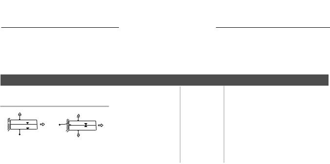
PIEZO SYSTEMS, INC.
2-PIEZO LAYER ELEMENTS
186 Massachusetts Avenue Cambridge , MA 02139 • Phone: (617) 547-1777 • Fax: (617) 354-2200 • Web: www.piezo.com • E-mail: sales@piezo.com
2-PIEZO LAYER EXTENSION MOTORS
STA N DA R D - BR A S S RE I N F O R C E D
PERFORMANCE: BRASS SHIM EXTENSION MOTORS
VALUES TO BE USED AS GUIDELINES
|
|
|
|
|
PART NUMBERS |
|
|
|
|
|
|
|
|
|
|
|
|
|
|
|
|
|
|
|
|
|
|
|
|
|
|
|||||||||
|
|
|
|
|
|
|
|
|
|
|
|
|
|
|
|
|
|
|
|
|
|
|
|
|
|
|
|
|
|
|
||||||||||
|
|
|
|
|
|
|
|
|
|
|
|
|
|
|
|
|
|
|
|
|
|
|
|
|
|
|||||||||||||||
|
|
|
|
|
|
|
|
|
|
|
|
|
|
|
|
|
|
|
|
|
|
|
|
|
|
|||||||||||||||
|
|
|
|
(BRASS REINFORCED EXTENDER) |
|
|
|
|
|
|
|
|
|
|
|
|
|
|
|
|
|
|
|
|
|
|
|
|
|
|
||||||||||
|
|
|
|
|
|
|
|
|
|
Extension Motor - Parallel |
|
|
|
|
|
|
|
|
|
|
|
|
|
|
|
|
|
|
|
|
|
|
|
|
|
|||||
|
|
|
|
|
|
|
|
|
|
|
|
|
|
|
|
|
|
|
|
|
|
|
|
|
|
|
|
|
|
|
|
|
|
|
||||||
|
|
|
|
|
|
|
|
|
|
|
|
|
|
|
|
|
C(nF)APACITANCE Operation)(Series |
|
|
C(nF)APACITANCE Operation)(Parallel |
|
VR(Vp)OLTAGEATED Operation)(Series |
|
|
VR(Vp)OLTAGEATED Operation)(Parallel |
|
|
FRREQUENCYESONANT (Hz) |
|
|
DFEFLECTIONREE (µm) |
|
|
FBORCELOCKED (N) |
|
|||||
|
|
|
|
|
∆ |
Xout |
|
|
|
|
|
|
∆ Xout |
|
|
|
|
|
|
|
|
|
|
|
|
|
|
|
|
|
|
|
|
|||||||
|
|
|
|
|
|
|
|
|
|
|
|
|
W(Grams)EIGHT |
|
|
S(N/m)TIFFNESS |
|
|
|
|
|
|
|
|
|
|
|
|||||||||||||
|
|
|
|
|
∆ |
Fout |
|
|
|
|
|
|
∆ Fout |
|
|
|
|
|
|
|
|
|
|
|
|
|
|
|
|
|
|
|
|
|
|
|
|
|
|
|
|
|
|
|
|
|
|
|
|
|
Vin |
|
|
|
|
|
|
|
|
|
|
|
|
|
|
|
|
|
|
|
|
|
|
|
|
|
|
|
|
|
|
|
|
|
|
Vin |
|
|
|
|
|
|
|
|
|
|
|
|
|
|
|
|
|
|
|
|
|
|
|
|
|
|
|
|
|
|
|
|
|
|
|
|
|
|
|
|
|
|
|
|
|
|
|
|
|
|
|
|
|
|
|
|
|
|
|
|
|
|
|
|
|
|
|
|
|
|
|
|
|
|
|
|
|
|
|
|
|
Y-poled for |
|
|
|
|
X-poled for |
|
|
|
|
|
|
|
|
|
|
|
|
|
|
|
|
|
|
|
|
|
|
|
|
|
|
|||||
|
series extension |
|
|
parallel extension |
|
|
|
|
|
|
|
|
|
|
|
|
|
|
|
|
|
|
|
|
|
|
|
|
|
|
||||||||||
|
operation (2 wire). |
|
|
operation (3 wire). |
|
|
|
|
|
|
|
|
|
|
|
|
|
|
|
|
|
|
|
|
|
|
|
|
|
|
||||||||||
|
|
|
|
|
|
|
|
|
|
|
|
|
|
|
|
|
|
|
|
|
|
|
|
|
|
|
|
|
|
|
|
|
|
|
|
|
|
|
|
|
|
|
|
|
|
|
|
|
|
|
|
|
|
|
|
|
|
|
|
|
|
|
|
|
|
|
|
|
|
|
|
|
|
|
|
|
|
|
|
|
|
|
|
|
|
|
|
|
|
|
|
|
|
|
|
|
|
|
|
|
|
|
|
|
|
|
|
|
|
|
|
|
|
|
|
|
|
|
|
|
|
|
|
|
|
|
|
|
|
|
|
|
|
|
|
|
|
|
|
|
|
|
|
|
|
|
|
|
|
|
|
|
|
|
|
|
|
|
|
|
|
|
|
.015” (.38mm) |
THICK |
|
|
|
|
|
|
|
|
|
|
|
|
|
|
|
|
|
|
|
|
|
|
|
|
|
|
|||||||||||||
|
T215-A4-103Y |
|
|
T215-A4-103X |
.30 |
|
2x10⁶ |
|
5 |
|
20 |
± 120 |
|
± 60 |
|
30,000 |
|
± 2.8 |
|
± 5 |
|
|||||||||||||||||||
|
|
|
|
|
|
|
|
|||||||||||||||||||||||||||||||||
|
T215-A4-203Y |
|
|
T215-A4-203X |
.60 |
|
3x10⁶ |
|
10 |
|
40 |
± 120 |
|
± 60 |
|
30,000 |
|
± 2.8 |
|
± 9 |
|
|||||||||||||||||||
|
T215-A4-303Y |
|
|
T215-A4-303X |
1.2 |
|
6x10⁶ |
|
20 |
|
80 |
± 120 |
|
± 60 |
|
30,000 |
|
± 2.8 |
|
± 19 |
|
|||||||||||||||||||
|
T215-A4-503Y |
|
|
T215-A4-503X |
6.0 |
|
8x10⁶ |
|
100 |
|
400 |
± 120 |
|
± 60 |
|
15,000 |
|
± 5.7 |
|
± 47 |
|
|||||||||||||||||||
|
T215-H4-103Y |
|
|
T215-H4-103X |
.30 |
|
2x10⁶ |
|
8 |
|
32 |
± 80 |
|
± 40 |
|
30,000 |
|
± 2.8 |
|
± 5 |
|
|||||||||||||||||||
|
T215-H4-203Y |
|
|
T215-H4-203X |
.60 |
|
3x10⁶ |
|
16 |
|
64 |
± 80 |
|
± 40 |
|
30,000 |
|
± 2.8 |
|
± 9 |
|
|||||||||||||||||||
|
T215-H4-303Y |
|
|
T215-H4-303X |
1.2 |
|
6x10⁶ |
|
32 |
|
128 |
± 80 |
|
± 40 |
|
30,000 |
|
± 2.8 |
|
± 19 |
|
|||||||||||||||||||
|
T215-H4-503Y |
|
|
T215-H4-503X |
6.0 |
|
8x10⁶ |
|
160 |
|
640 |
± 80 |
|
± 40 |
|
15,000 |
|
± 5.7 |
|
± 47 |
|
|||||||||||||||||||
.020” (.51mm) |
THICK |
|
|
|
|
|
|
|
|
|
|
|
|
|
|
|
|
|
|
|
|
|
|
|
|
|
|
|||||||||||||
|
T220-A4-103Y |
|
|
T220-A4-103X |
.40 |
|
2x10⁶ |
|
3.5 |
|
14 |
± 180 |
|
± 90 |
|
29,500 |
|
± 3.2 |
|
± 7 |
|
|||||||||||||||||||
|
|
|
|
|
|
|
|
|||||||||||||||||||||||||||||||||
|
T220-A4-203Y |
|
|
T220-A4-203X |
.80 |
|
4x10⁶ |
|
7 |
|
29 |
± 180 |
|
± 90 |
|
29,500 |
|
± 3.2 |
|
± 14 |
|
|||||||||||||||||||
|
T220-A4-303Y |
|
|
T220-A4-303X |
1.6 |
|
9x10⁶ |
|
15 |
|
58 |
± 180 |
|
± 90 |
|
29,500 |
|
± 3.2 |
|
± 29 |
|
|||||||||||||||||||
|
T220-A4-503Y |
|
|
T220-A4-503X |
8.0 |
|
11x106 |
|
73 |
|
292 |
± 180 |
|
± 90 |
|
14,750 |
|
± 6.4 |
|
± 72 |
|
|||||||||||||||||||
|
T220-H4-103Y |
|
|
T220-H4-103X |
.40 |
|
2x10⁶ |
|
6.0 |
|
24 |
± 120 |
|
± 60 |
|
29,500 |
|
± 3.2 |
|
± 7 |
|
|||||||||||||||||||
|
T220-H4-203Y |
|
|
T220-H4-203X |
.80 |
|
4x10⁶ |
|
12 |
|
48 |
± 120 |
|
± 60 |
|
29,500 |
|
± 3.2 |
|
± 14 |
|
|||||||||||||||||||
|
T220-H4-303Y |
|
|
T220-H4-303X |
1.6 |
|
9x10⁶ |
|
24 |
|
96 |
± 120 |
|
± 60 |
|
29,500 |
|
± 3.2 |
|
± 29 |
|
|||||||||||||||||||
|
T220-H4-503Y |
|
|
T220-H4-503X |
8.0 |
|
11x106 |
|
120 |
|
480 |
± 120 |
|
± 60 |
|
14,750 |
|
± 6.4 |
|
± 72 |
|
|||||||||||||||||||
|
|
|
|
|
|
|
|
|
|
|
|
|
|
|
|
|
|
|
|
|
|
|
|
|
|
|
|
|
|
|
|
|
|
|
|
|
|
|
|
|
.026” (.66mm) |
THICK |
|
|
|
|
|
|
|
|
|
|
|
|
|
|
|
|
|
|
|
|
|
|
|
|
|
|
|||||||||||||
|
T226-A4-103Y |
|
|
T226-A4-103X |
.51 |
|
3x10⁶ |
|
2.5 |
|
10 |
± 260 |
|
± 130 |
|
29,000 |
|
± 3.4 |
|
± 10 |
|
|||||||||||||||||||
|
|
|
|
|
|
|
|
|
|
|
||||||||||||||||||||||||||||||
|
T226-A4-203Y |
|
|
T226-A4-203X |
1.1 |
|
6x10⁶ |
|
5 |
|
20 |
± 260 |
|
± 130 |
|
29,000 |
|
± 3.4 |
|
± 20 |
|
|||||||||||||||||||
|
T226-A4-303Y |
|
|
T226-A4-303X |
2.1 |
|
12x106 |
|
10 |
|
40 |
± 260 |
|
± 130 |
|
29,000 |
|
± 3.4 |
|
± 40 |
|
|||||||||||||||||||
|
T226-A4-503Y |
|
|
T226-A4-503X |
10.3 |
|
15x106 |
|
50 |
|
200 |
± 260 |
|
± 130 |
|
14,500 |
|
± 6.8 |
|
± 100 |
|
|||||||||||||||||||
|
T226-H4-103Y |
|
|
T226-H4-103X |
.51 |
|
3x10⁶ |
|
4 |
|
16 |
± 170 |
|
± 85 |
|
29,000 |
|
± 3.4 |
|
± 10 |
|
|||||||||||||||||||
|
T226-H4-203Y |
|
|
T226-H4-203X |
1.1 |
|
6x10⁶ |
|
8 |
|
32 |
± 170 |
|
± 85 |
|
29,000 |
|
± 3.4 |
|
± 20 |
|
|||||||||||||||||||
|
T226-H4-303Y |
|
|
T226-H4-303X |
2.1 |
|
12x106 |
|
17 |
|
68 |
± 170 |
|
± 85 |
|
29,000 |
|
± 3.4 |
|
± 40 |
|
|||||||||||||||||||
|
T226-H4-503Y |
|
|
T226-H4-503X |
10.3 |
|
15x106 |
|
85 |
|
340 |
± 170 |
|
± 85 |
|
14,500 |
|
± 6.8 |
|
± 100 |
|
|||||||||||||||||||
-103, -203, and -303 performance is based on a 1.0” bending length. -503 performance based on 2.0” bending length. Suitable for cryogenic use.
30 |
CATALOG #6, 2005 |