

Chapter 7
Embedding
Bluetooth
Applications
Solutions in this chapter:
■Understanding Embedded Systems
■Getting Started
■Running an Application under the Debugger
■Running an Application on BlueCore
■Using the BlueLab Libraries
■Deploying Applications
Summary
Solutions Fast Track
Frequently Asked Questions
265

266 Chapter 7 • Embedding Bluetooth Applications
Introduction
Bluetooth wireless technology is proving popular for handheld mobile devices such as mobile phones and headsets, which have very limited space and power. Using an extra host processor to run applications takes up extra space, uses extra power, and adds cost, too. For the ultimate in compact design, low cost, and energy efficiency Bluetooth applications can be run directly on the same processor that drives the Bluetooth baseband.
Vendors who supply designs for Bluetooth Application-Specific Integrated Circuits (ASICs) also provide interfaces which allow custom applications to run on the same microprocessor which drives the Bluetooth baseband. It is also possible to run applications on commercially available chips.This chapter looks at embedded applications using as an example Cambridge Silicon Radio (CSR)’s BlueLab system for programming embedded applications on BlueCore chips.
Not every application is suitable for embedding on a BlueCore chip. Small simple applications such as the Headset and Audio Gateway profiles, as well as things like central heating controllers or TV remote controllers, are suitable for embedding on a single chip. High-bandwidth or complex applications such as a local area network (LAN) access point are better suited to implementation using a separate host processor.
This is because when an application is running on the same chip as a Bluetooth protocol stack, the application and firmware stack must share the available RAM on the chip. For a single channel RFCOMM-based application, the available RAM is several hundred words.The application code and its constant data must fit into just under 32K words.
Embedded applications running on a BlueCore chip are run under an interpreter called the Virtual Machine (VM). Interpreting application opcodes confers a significant performance penalty which limits suitable applications. For devices such as headsets, most of the time all that is happening is audio input/output (I/O). Control operations are comparatively infrequent, and involve simpler operations than would happen on devices such as LAN access points.
In this chapter, we’ll look at some of the implications of these limitations and give some examples of how much can still be done in embedded applications.We’ll take you through how to build applications which can be run on BlueCore, and explain how to build run and debug both on PCs and on the BlueCore chip itself.
What you need to know before reading this chapter is:
■The C programming language
■The basics of embedded programming: tasks and message queues
www.syngress.com

Embedding Bluetooth Applications • Chapter 7 |
267 |
Understanding Embedded Systems
This section assumes that you’ve done some programming, but you don’t have embedded experience. If you’ve worked with embedded systems before, you might want to skip straight to the “Getting Started” section. For the rest of you, we’ll go over tasks, queues, stacks, interrupts, and the difference between running code on a PC and code embedded on hardware.
Understanding Tasks, Timers, and Schedulers
In a Bluetooth system, there are many different tasks to take care of: Link Management messages must be processed; incoming data must be dealt with as it arrives; outgoing data has to be sent to the baseband and radio; if there is a separate host communications through the host controller interface this must be addressed; all this and more must be handled simultaneously. Having a microprocessor for each task would be far too expensive, so the solution is for one microprocessor to swap between tasks, spending a little time on each in turn.This is called multi-tasking.
Each task has its own call stack, its own I/O queues, and each task gets a turn at the processor.There is one task which coordinates the rest.This is usually called a kernel, but is also referred to as a scheduler. Different embedded systems handle swapping between tasks in different ways, some assign priorities to tasks, so that a lowpriority task does not stop a high-priority task from running.The BlueCore01 system has a simple round-robin scheduler, which runs each task in turn.
The scheduler stops running a task when the task blocks. A task blocks by making a system call which waits for an event.This behavior means that the scheduler is vulnerable to a task putting itself into an infinite loop. Since the task would never block, no other task would ever get a chance to run.
On the face of it, this means you could disable the whole Bluetooth system if your application didn’t block often enough. Since there are many time-critical operations within the Bluetooth stack, you could easily stop the stack from working properly.To solve this problem BlueCore provides an environment called the Virtual Machine which protects the stack code from applications which try to take too much processor time. Instead of your application code being called directly, the scheduler calls the Virtual Machine.The Virtual Machine then runs a number of operations through its interpreter, and afterward blocks so the scheduler can call another task. It doesn’t matter if your code is in an infinite loop, the Virtual Machine will still only run a preset number of your application’s instructions, so your endless loop can’t run endlessly!
www.syngress.com

268 Chapter 7 • Embedding Bluetooth Applications
The processor time used by other tasks in the system will vary. For instance, when the Link Manager task is in the middle of negotiating link configuration, it will require more processor time than when no Link Management messages are being received.This means that the time between calls to the Virtual Machine will vary.The impact on your application is that BlueCore does not provide Real Time Operating System (RTOS) capabilities because it makes no guarantees regarding how often it will call your application code.
Understanding Messaging and Queues
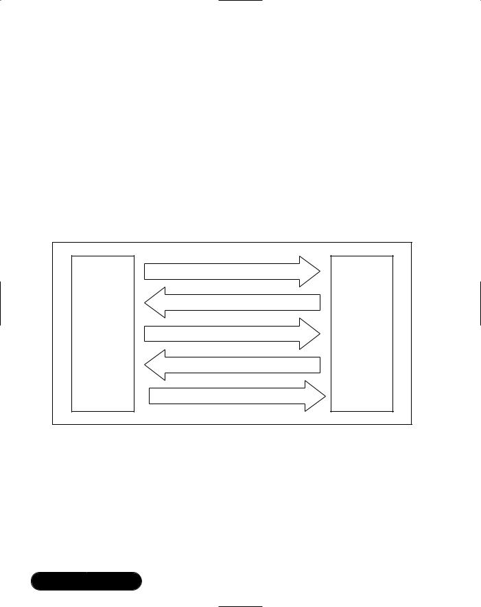
The tasks in a system need some way of passing information to one another. One task may not be ready to receive a message at the same time another task wants to send it, so some way is needed to store messages for a task until it is ready to deal with them.
Each task has a queue where messages can wait to be picked up. A queue is a first-in first-out (FIFO) data structure.That is to say, the first message to be put into the queue is the first message to come out: messages are received in the same order that they were sent. Several different tasks can send messages to one task by putting messages onto that task’s queue.
When a message is created and sent, some memory is temporarily allocated to store the message. It then waits on the queue until it can be processed by the receiving task. After processing, the message is destroyed and its memory is returned to the free pool.
The message queues allow tasks to send one another messages asynchronously: it doesn’t matter if tasks run at different speeds, the queues buffer messages so that they can still communicate.The exact mechanisms for sending and receiving messages are explained in more detail in the following section on the message library:“Using Tasks and Messages.”
Using Interrupts
Embedded systems need to react to the outside world. A typical embedded system will be connected to some electronic hardware and must react to signals from it, and send signals to control it. Interrupts provide the means for hardware to interact with software. An interrupt is a signal which makes the CPU stop running its current program and jump to a special interrupt routine.The interrupt routine is essentially just another subroutine—you just get to the interrupt routine because of an interrupt signal, rather than because you were called by another function.
www.syngress.com

Embedding Bluetooth Applications • Chapter 7 |
269 |
Hardware is connected to pins which cause interrupts—commonly called interrupt lines. BlueCore01 has two interrupt lines available for connecting up to custom hardware. But keep in mind, the number of interrupt lines available will vary from system to system.
On BlueCore01 the interrupt routines are already written. If the interrupt lines change state, the interrupt routine will cause an event to be generated.The event is VM_EVENT _PIOINT, which stands for Virtual Machine Event Parallel Input Output Interrupt.
Interrupts usually have to be enabled before they can be used.This stops lines which are not currently in use, causing undesirable effects. BlueLab works just the same: by default, no events will happen, if you want your application to respond to an event, you must enable that event using the following call:
uint16 EventEnable(vm_event_source source, int enable);
So, to enable the PIO interrupt event you use:
EventEnable(VM_EVENT_PIOINT, 1);
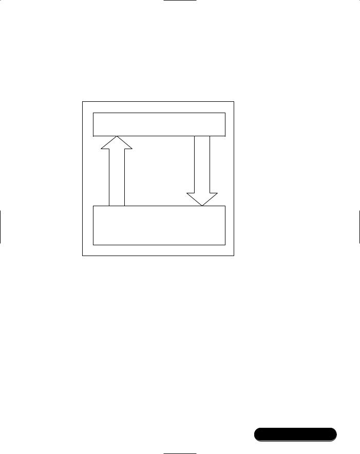
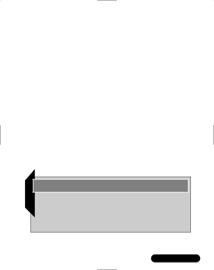
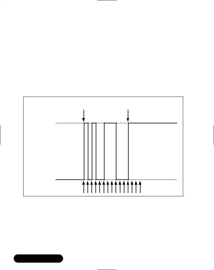
A common use for an interrupt line is to connect a push button switch so that software can react to a user pressing a button. One problem, which is not immediately obvious, is that switches don’t just move straight from one state to another. As the contacts close, there is usually a “bounce,” which causes the switch to rapidly open and close several times (see Figure 7.1). Software can run fast enough for one push on a button to trigger several interrupts.
The solution to the problem is to debounce interrupt lines which are connected to pushbuttons, keyboards, or any other hardware which might oscillate before settling to a stable value. On many embedded systems, you will have to write a debounce function which catches the first interrupt from a line, disables interrupts, and then samples the line state periodically until it is stable. System code on BlueCore01 includes a debounce engine, and BlueLab provides a function for you which accesses it. All you need to do is call:
Void Debouncesetup(uint16 mask, uint16 count, uint16 period);
This sets up the debounce engine so that when the interrupt line specified by the mask parameter changes, the engine begins reading the pin at the interval specified by the period parameter (in milliseconds), until it has seen the same value count times. Once the line is stable, the engine sends the VM_EVENT_PIOINT event to application code.The application code can then get the stable value of the interrupt line using the call:
www.syngress.com

270 Chapter 7 • Embedding Bluetooth Applications
uint16 DebounceGet (void);
So, for instance, to sample PIO line 5 at 2 millisecond (ms) intervals and wait until it has been stable four times in a row, you would use:
Void Debouncesetup(1 << 5, 4, 2);
Setting the sampling period to zero switches off debouncing, so you then get an event for every single transition of the line.To switch off debounce on PIO line 5, you would use:
DebounceSetup(1<<5, 1, 0);
Figure 7.1 Switch Bounce
User presses |
Switch stops |
switch here |
oscillating here |
Switch on |
|
(interrupt line |
|
high) |
|
Switch off |
|
(interrupt line low) |
Keep sampling until |
|
|
|
switch is in a stable state |
Hardware interrupts aren’t the only type of interrupt. Many systems also allow software to generate interrupts.This is done when errors happen, such as a divide by zero operation, or an attempt to access memory that doesn’t exist. Software interrupts are usually irrecoverable and result in a system reset.To prevent this from happening, the Virtual Machine interpreter checks user application code on BlueCore for illegal accesses.
www.syngress.com

Embedding Bluetooth Applications • Chapter 7 |
271 |
Getting Started
BlueLab builds code for CSR’s BlueCore chips. So, in addition to BlueLab, you will need a Casira development system.The development tools run on a Win32 PC—therefore, you will need administrator rights on the PC to install the tools.
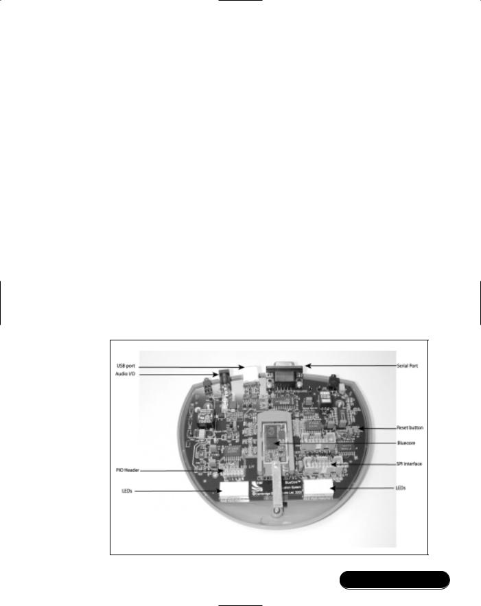
The BlueCore module is supplied on a carrier board which slots into a blue plastic carrier in the center of the Casira (see Figure 7.2).The circuitry on this board is what would be used in most end-user products.The rest of the Casira development kit provides extra facilities to allow you to develop and debug applications, providing a variety of useful interfaces:
■SPI interface Connects to a PC parallel port, and allows you to reconfigure the Casira using the PSTool utility. Images can also be downloaded to the Casira using the Serial Peripheral Interface (SPI).
■Serial interface Connects to a PC serial port. BlueLab uses BlueCore Serial Protocol (BCSP), so you must ensure your Casira is configured to use BCSP. (Casiras are sold ready to use BCSP.)
■USB port Connects to a PC USB port, and supports the Bluetooth Specification’s USB protocol (H2) when correctly configured.
Figure 7.2 Casira Development Kit
www.syngress.com

272Chapter 7 • Embedding Bluetooth Applications
■Audio I/O An audio jack which connects to the headsets supplied with the Casira.
■LEDs These can be used to monitor applications running on the BlueCore chip.
■PIO lines Parallel Input-Output lines; useful for connecting custom hardware.
Developing & Deploying…
BCSP and H4
The 1.1 Bluetooth Specification provided two serial interfaces: UART (H4) and RS232 (H3). Casiras can be configured to use the UART (H4) protocol across its serial port interface, but they are sold configured to use BlueCore Serial Protocol (BCSP). BCSP provides extra error checking on the serial interface, so it is more reliable in situations where errors can happen on the serial interface. BCSP also provides separate channels for voice, control, and data. This allows data to be flow-controlled while voice traffic flows remain uninterrupted.
Some stack vendors support BCSP, but not all do. To compensate, Casiras may be reconfigured to support the 1.1 Specification’s UART (H4) interface.
The serial port settings are stored in the BlueCore persistent store (flash). A Persistent Store tool (PSTool) utility is available to change these settings.
The procedure for changing the serial port settings to BSCP is as follows:
■Connect the SPI cable between the Casira and a PC parallel port.
■Give the PSTool utility low-level access to the parallel port by installing a device driver. To do this, run the batch file BlueLab20\bin\InstParSPI.bat (this requires administrator rights).
■Register the PSTool user interface in the Windows registry by running BlueLab20\bin\RegPSToolocx.bat.
■Run the PSTool utility, selecting SPI interface.
■Access the developer list of tools by pressing Ctrl+Alt+D.
■Set the key Host Interface to UART link running BCSP.
Continued
www.syngress.com

Embedding Bluetooth Applications • Chapter 7 |
273 |
■ Set the key UART Configuration Bitfields to 6.
To set a Casira to use the 1.1 Specifications UART protocol (H4), the following settings are used:
■Set the key Host Interface to UART link running H4.
■Set the key UART Configuration Bitfields to 168.
Note that to set a PS key, the Set button in the PSTool application must be pressed. Simply typing in the new value will not work. To be absolutely sure you have successfully set the new value, you can use the Read button to read back the current value.
Installing the Tool Set
BlueLab uses Cygwin, a Unixlike environment run under Windows. Cygwin is installed by running setup.exe from the Cygwin directory on the BlueLab CD. When prompted, choose to Install from local directory, and press Next twice. Now choose your installation directory, Unix text file type, and install for All.This installs all the tools which BlueLab needs.
The debugger from BlueLab is written in Java and requires version 1.3 or later of the Java2 runtime environment.To install the Java2 runtime environment, run the file setup.exe from the Java directory on the CD and follow the instructions. Finally, install BlueLab by running BlueLab.exe from the main directory on the CD.
Building a Sample Application
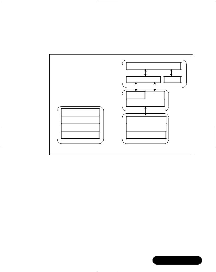
To test the installation, it is a good idea to compile a sample application. Starting Cygwin, go to the relevant directory and run make.
$ cd /cygdrive/c/BlueLab20/apps/hello
$ make
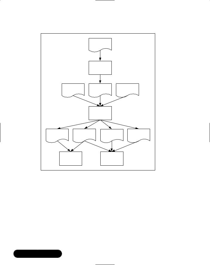
The main compiler xap-local-xap-gcc is derived from the GNU C compiler. This compiles the C code and produces an object file hello.o.The linker then works with the assembler xap2asm to analyze the object file, link in libraries and produce the application files hello.app, hello.dbg, hello.sym, and hello.xap. (See Figure 7.3.)
www.syngress.com

274 Chapter 7 • Embedding Bluetooth Applications
Figure 7.3 The BlueLab Tool Chain
|
|
hello.c |
|
|
|
gcc |
|
|
libc.a |
hello.o |
crt0.o |
|
|
ld |
|
hello.app |
hello.dbg |
hello.sym |
hello.xap |
|
chip / emulator |
debugger |
|
All you have done so far is build a “Hello World” program—this is not a BlueCore image, and you can’t download it to the Casira yet. But you can use it to play with the debugging tools.
Running an Application under the Debugger
The debugger allows you to set breakpoints as well as single-step your code, and has many of the functions you find in a typical modern debugging environment. Code executes on the PC, but if you need to use functions from the BlueCore chip, such as the Radio or PIO, these are handled by the attached Casira.
www.syngress.com

Embedding Bluetooth Applications • Chapter 7 |
275 |
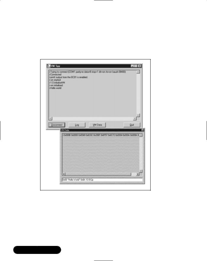
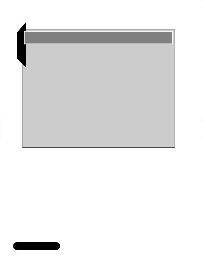
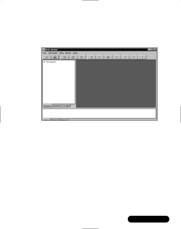
Start off appdebug.jar by double-clicking the appdebug.jar icon in the C:\BlueLab20\bin directory.You should see the debugger window as shown in Figure 7.4.
Figure 7.4 Debugger Main Window
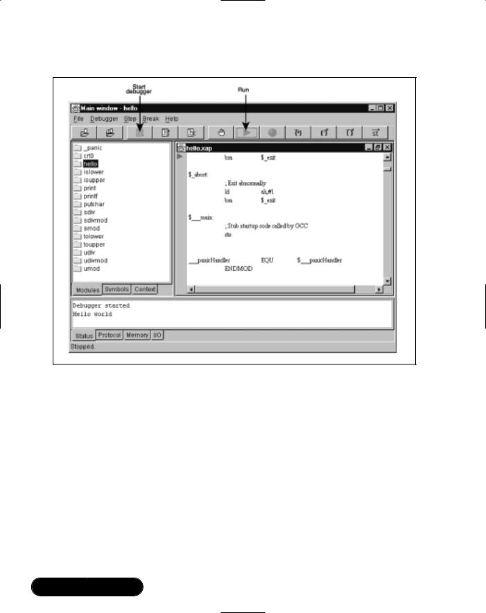
Select File | Open project, and load hello.sym. Once the project has loaded, you can browse the application downloaded using the Modules and Symbols tabs. Click a module name to see that module. Right-click a symbol to see the different places it appears.
Without communications, the debugger will report a problem and will fail to start.You can modify the comm port settings on the chip using PSTool, and editing the UART: baud rate.The Host Interface must be BCSP.To adjust the PC baud rate to match the Casira, select File | Preferences and click the
Comms tab.
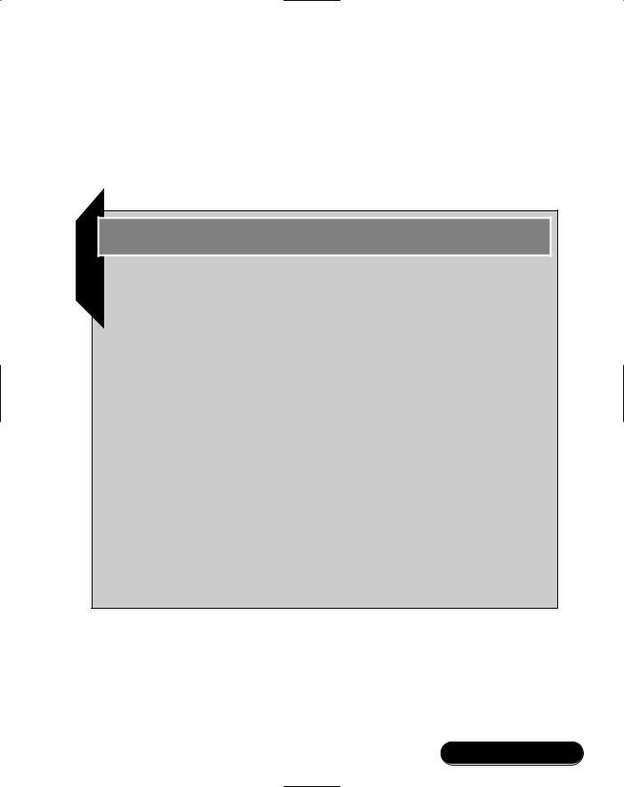
To run the program under the debugger, click the Start Debugger button. This opens communications to the Virtual Machine, lets you set break points, and allows you to run the code. Now, run the code by pressing the Run button.You should see “Hello World” in the debug output window (see Figure 7.5).
The Hello World program will run, output “Hello world,” and then exit. It’s not exactly a killer application, but it does verify that you have successfully installed all the tools, and configured the Casira correctly.
www.syngress.com

276 Chapter 7 • Embedding Bluetooth Applications
Figure 7.5 Active Debugger Window
Using Plug-ins
The debugger can simulate code running on a BlueCore chip, and by communicating with the Casira can also use the radio and PIO ports on the BlueCore itself. Embedded applications are likely to run on custom hardware, so it may also be necessary to simulate extra hardware. For example, if you are creating a headset, a plug-in to simulate the buttons and lights on your headset will make it much easier to debug your headset application.
Simulating custom hardware is done by adding plug-ins to the debugger.The debugger is written in Java, so to create a plug-in, you just derive a new class to extend the existing Java class JComponent. Custom hardware will be controlled by the BlueCore chip’s PIO pins, so plug-ins which simulate custom hardware must implement the PIOPlugin interface.
www.syngress.com

Embedding Bluetooth Applications • Chapter 7 |
277 |
BlueLab includes an abstract PIOPanel class, which extends Jcomponent, and implements the PIOPlugin interface. It also provides useful functions for constructing and registering controls.
The following example is based on PIOPanel.The class implements two functions: tabName, which returns a string giving the name of the panel as it appears within the debugger, and the constructor function, which creates items that are displayed within the panel, positions them in the correct place, and informs the underlying PIOPanel about them.The items added to the panel must all implement the “Updater” interface:
public interface Updater
{
void setEnabled(boolean show); void update(int on, int isout); void setDriver(PIODriver lis);
}
The updater interface specifies three functions that the control should support:
■setEnabled is called for each item in the panel whenever the panel becomes activated or deactivated. It is commonly used for graying out the controls.
■update is most useful for output items (lights).This interface function is called for each item in the panel whenever the PIO bits change state.
■PIODriver is used to drive PIO bits.This is needed to accept input from the user (e.g., a button press). An instance of “PIODriver” is passed to the item’s “setDriver” function when the item is added to the PIOPanel.
If the hardware being simulated is just simple buttons or lights, then these can be added much more easily.The PIOPanel class provides utility functions that produce labels, buttons, and lights that are integrated into the panel in the correct way.These functions are:
//produces a simple text label, that is enabled in the correct manner. public JLabel makeLabel(String label);
//produces a simple light, that is connected to one bit of the PIO port
www.syngress.com

278Chapter 7 • Embedding Bluetooth Applications
public OnOffLight makeLight(int bit);
// produces a simple push-button, connected to one bit of the PIO port public JToggleButton makeToggleButton(String label, int bit);
public JButton makeButton(String label, int bit);
Using these simple primitives, it is now possible to create the Headset plug-in panel.We begin by adding variables for each element of the panel, and creating them with calls to the make* functions.Then we use the initialization function to position the elements on the panel in a pleasing arrangement.This is achieved through the use of the standard Java Swing functions. A simplified version of the headset code is shown in the following:
// The new class 'Headset' is derived from the class 'PIOPanel' public class Headset extends PIOPanel
{
// The labels
private JLabel volumeLabel = makeLabel("Volume"); private JLabel powerLabel = makeLabel("Power"); private JLabel[] labels = { volumeLabel, powerLabel };
// The Light
private OnOffLight powerLight = makeLight(9);
// The Buttons
private JToggleButton talkButton = makeToggleButton("!!Talk!!", 2); private JToggleButton upButton = makeToggleButton("Up", 4); private JToggleButton downButton = makeToggleButton("Down", 5);
//A function to return the name of the panel public String tabName()
{ return "Headset"; }
//The constructor - contains initialization code public Headset()
{
www.syngress.com

Embedding Bluetooth Applications • Chapter 7 |
279 |
// bracket the initialization function a try/catch block try
{jbInit(); } catch(Exception e)
{e.printStackTrace(); }
}
private void jbInit() throws Exception
{
//We want everything laid out on a grid setLayout(new GridLayout());
//Set the alignment of the labels for(int i = 0; i < labels.length; ++i)
{ labels[i].setHorizontalAlignment(SwingConstants.RIGHT); }
//Add the items to the panel
add(talkButton, new GridConstraints(0, 1, 1, 1, 0.0, 0.0, GridConstraints.CENTER, GridConstraints.HORIZONTAL, new Insets(4, 8, 4, 8), 0, 0));
add(volumeLabel, new GridConstraints(1, 1, 1, 2, 0.0, 0.0, GridConstraints.WEST, GridConstraints.NONE,
new Insets(4, 8, 4, 4), 0, 0));
add(upButton, new GridConstraints(2, 1, 1, 1, 0.0,0.0, GridConstraints.CENTER, GridConstraints.HORIZONTAL, new Insets(4, 4, 4, 8), 0, 0));
add(downButton, new GridConstraints(2, 2, 1, 1, 0.0, 0.0, GridConstraints.CENTER, GridConstraints.HORIZONTAL, new Insets(4, 4, 4, 8), 0, 0));
add(powerLabel, new GridConstraints(3, 1, 1, 1, 0.0, 0.0, GridConstraints.WEST, GridConstraints.BOTH,
new Insets(4, 8, 4, 4), 0, 0));
add(powerLight, new GridConstraints(4, 1, 1, 1, 0.0, 0.0, GridConstraints.CENTER, GridConstraints.NONE,
www.syngress.com

280 Chapter 7 • Embedding Bluetooth Applications
new Insets(4, 4, 4, 8), 0, 0));
// Everything should start off disabled
setEnabled(false);
}
}
BlueLab includes example plug-ins for a Headset,Telephone button grid, a 16-bit port expander using the I2C bus, a seven segment display and an output trace which reflects the state of the PIO pins. Rather than try to write plug-ins from scratch, you should pick the example closest to your application’s needs and modify it as necessary.
Debugging under BlueLab
The Memory tab at the bottom of the main debugger window will show all active memory regions including their start and extent. If any address has a blank value, it means that address isn’t acceptable.To follow a pointer from the variable window, just right-click it.This moves the memory window to that location.
If the application crashes, the debugger will stop just after the offending instruction.The call stack will show in the middle of the Context panel at the left of the main window. As you double-click the call stack, the source and variable displays are updated to that stack context.
Running an Application on BlueCore
To run a final application on the Casira, you must merge the application with a full Bluetooth stack.The Casira development kit arrives preloaded with a firmware image which allows the Casira to run the lower layers of the Bluetooth stack.
Figure 7.6 shows how an application image differs from the default Casira image.The application image has extra protocol stack layers: Logical Link Control and Adaptation Protocol (L2CAP), RFCOMM and Service Discovery Protocol (SDP).These are the protocol stack layers required to support the serial port profile, and are also used to support simple profiles based on the serial port profile such as the Headset profile.These stack layers are written by Mezoe and are collectively called BlueStack. BlueLab provides a royalty-free version of these stack layers for use on BlueCore chips. Above the BlueStack layers, a Connection Manager handles management of RFCOMM connections.The Connection Manager library is provided with BlueLab to make it easier to manage connec-
www.syngress.com

Embedding Bluetooth Applications • Chapter 7 |
281 |
tions, but it is not compulsory to use it: if it does not meet the needs of your application, you can write your own Connection Manager.
Figure 7.6 |
Default Image and Image with Application |
|||
|
|
|
Application |
|
|
|
Connection Manager |
Libraries |
|
|
|
|
|
Virtual Machine |
|
|
SDP |
RFCOMM |
|
|
|
L2CAP |
|
|
Host Controller Interface |
Mezoe |
BlueStack |
|
|
|
|
|
||
Link Manager |
Link Manager |
|
||
Link Controller |
Link Controller |
|
||
|
Radio |
Radio |
|
|
CSR BlueCore stack |
CSR Bluecore stack |
|
||
Default image |
Image with full stack and application |
At the top of the application stack is the VM.The Virtual Machine allows the Connection Manager, Libraries, and application software to run in a protected memory space. Application software is compiled into Virtual Machine opcodes. As this is run, the Virtual Machine checks each instruction for invalid memory access. In this way, the Virtual Machine guarantees that your application software cannot interfere with correct running of the Bluetooth protocol stack.
When you are running applications under the debugger, you must have RFCOMM present on the Casira to drive the radio. However your application will actually be running under the debugger on a PC, so you do not want an image with your application built into it.The answer is to load the Casira with a “null” image—this is a firmware image that contains the Virtual Machine, but has no valid application. Note that if you have version 2.1 or later, you can have an image with an on-chip application installed; the on-chip application will automatically be disabled when the debugger is connected.
www.syngress.com

282 Chapter 7 • Embedding Bluetooth Applications
Developing & Deploying…
Virtual Machine Scheduling
The on-chip scheduler only allows a limited number of Virtual Machine instructions before giving another process some time. This means that you can not rely on an application running on the Virtual Machine to react quickly. This can be demonstrated by using VM code to toggle a PIO line. Consider the following code fragment:
while (1)
{
val ^=4;
PIOset (OUTPUT_BITS, val);
}
You should not write real code like this, as a continuous while loop is very bad for power consumption and can stop the chip from going into sleep states, but it is a useful routine to illustrate the scheduling of the Virtual Machine.
The while loop should execute, endlessly toggling the PIO line. If the line was connected to an LED, we would expect to see it shining brightly, as it flickers faster than the human eye can follow. In fact, if you follow the PIO line on an oscilloscope, you will see that what happens is the while loop toggles the PIO line at 3 KHz for 3 ms then remains in the last state for a while before another 3 ms of switching. (The exact time between bursts of switching varies depending on the other processes running.)
When writing applications for the Virtual Machine, you must bear in mind that your code will run fairly slowly since it’s being interpreted. The preceding toggling speed equates to an equivalent clock speed of, at best, 40 KHz. Of course, the chip’s real clock runs much faster, but your application effectively sees a slower clock because it is running through the delays caused by guarding the Bluetooth protocol stack.
You must also allow for the delays caused by other tasks being scheduled, as shown by the gaps in toggling the PIO line in the previous example.
Despite all these delays, it is still possible to write many useful applications, and even implement complete profiles under the Virtual Machine.
www.syngress.com

Embedding Bluetooth Applications • Chapter 7 |
283 |
To program the Casira with a null image, simply go to the null project in the apps directory and run make bc01.
$ make bc01
This calls the command line version of the BlueFlash utility and downloads the image to the Casira for you. (You can also download images to the Casira across the SPI interface using a GUI version of the BlueFlash utility. Just run up BC01flash.exe and follow the instructions.)
Debugging Using VM Spy
Debug output from the application can be viewed using the VM Spy utility.To begin using VM Spy, complete the following steps:
1.Make sure the debugger isn’t running, and nothing else is using the PC serial port.
2.Ensure the Casira serial cable is connected to the PC.
3.Make sure the Casira is configured to use BCSP.
4.Run VMSpy.exe.
5.Select Connect.
6.Select the COM port and baud rate that match the Casira configuration.
Figure 7.7 shows the VM Spy window (this figure also shows the VM data window which is explained in the next section,“Using VM Packets”). If the VM Spy window doesn’t open, check to make sure the serial cable is connected correctly, that the Casira is configured for BCSP, and that no other applications are using the COM port.
VM Spy connects to the Casira, and debugging output (from BCSP Channel 11) is displayed in the main window.The window has several buttons which can be used to control the debugging session:
■Disconnect This button disconnects from the Casira, but leaves the debugger window open.
■Log This button allows a session to be logged to a file.
■VM Data This button activates a window showing traffic on the VM data channel (BCSP Channel 13). Of course, this only works if the application makes use of the VM data channel.The bottom of the VM
www.syngress.com

284 Chapter 7 • Embedding Bluetooth Applications
Data window includes an edit box which can be used to send commands to the Casira.
■Quit This button shuts down the debugger.
Figure 7.7 The VM Spy Window
Using VM Packets
Applications running under the Virtual Machine can use BSCP Channel 13 to communicate with a host.The user application can send and receive packets of 16-bit data. For the final product, you will need to write software on the host to form the other end of the connection, but while developing embedded applications, Channel 13 can be a useful debugging tool. Applications which do not use
www.syngress.com

Embedding Bluetooth Applications • Chapter 7 |
285 |
BCSP Virtual Machine packets can still communicate with Virtual Machine packets. (See Figure 7.8.) On USB and H4 they are sent over the Host Controller Interface (HCI) using the manufacturer’s extension command.
Figure 7.8 Sending and Receiving Packets across Channel 13
|
Host |
HostSendMessage |
HostGetMessage |
|
Application |
(running under Virtual Machine) |
Incoming packets from the host cause a VM_EVENT_HOST event.The packets can then be retrieved using the HostGetMessage function. If there is no packet waiting, HostGetMessage returns NULL, otherwise a pointer to a new block of dynamic memory containing the packet is returned.This memory must be freed by the application once the application has finished with the packet.
The HostSendMessage function is used to send a message to the host.The application uses malloc to allocate a block of memory for the packet, and fills it in with the packet.Then HostSendMessage is passed a pointer to the memory block. The application can not access the memory block after the call, and should remove all references to it.
The Virtual Machine packet format is very simple (see Figure 7.9).The packet begins with a 16-bit word length field, which gives the total length of the packet, including the header. Note that the length is in 16-bit words, not in bytes.
www.syngress.com

286 Chapter 7 • Embedding Bluetooth Applications
Figure 7.9 Format of a Virtual Machine Packet
Length |
Sub-type |
Data |
16 bits |
16 bits |
(Length - 2) x 16 bits |
The second field is a 16-bit sub-type word.The sub-type must be set to a value between 0 − 127 (0x00 − 0x7f).The sub-type is useful to indicate the type of the packet to the code at either end.
The rest of the packet can contain any 16-bit data.
The code fragments that follow show how the HostSendMessage and
HostGetMessage can be used.
#include <host.h> |
/* HostSendMessage and HostGetMessage */ |
#include <stdlib.h> /* malloc */ |
|
... |
|
/* Send a |
small packet to the host */ |
||
uint16* data = (uint16 *) malloc(3 * sizeof(uint16)); |
|||
if(data != NULL) |
|
||
{ |
|
|
|
data[0] |
= |
3; |
/* length */ |
data[1] |
= |
0x7e; |
/* sub-type */ |
data[2] |
= 0x1234; /* data */ |
||
HostSendMessage(data); |
|||
data = |
NULL; |
/* removing reference to memory block */ |
|
} |
|
|
|
/* receive a packet from the host */ if((data = HostGetMessage()) != NULL)
{
/* do something with the data here */ free(data);
}
www.syngress.com

Embedding Bluetooth Applications • Chapter 7 |
287 |
The VM Data window of VM Spy can be used to send VM packets to test an application.The edit box at the bottom of the VM Data window is used to send commands to the Casira on BCSP Channel 13.The line can be used to input hexadecimal, decimal, or octal numbers.The line can also take character strings delimited with a quotation mark (").
The first entry on the edit window line is the sub-type number.This is followed by the contents of the packet.VM Spy will automatically calculate the packet length and fill in that field for you, so you don’t need to worry about the length field.
Packing Format in Messages
The XAP2 processor on BlueCore works with 16-bit words.This means that single byte parameters are packed into 16-bit words.There are a few other rules to bear in mind when interpreting data structures from BlueCore:
■8-bit values are sent as a 16-bit word, padded by setting the most significant byte to 0x00.
■16-bit words are sent the least significant byte first.
■24-bit words are sent as a 32-bit long word, padded by setting the most significant byte to 0x00.The most significant word is sent first.
■32-bit long words are sent as two 16-bit words with the most significant word first.
■Pointers are sent as two bytes with their values set to [0x00 0x00].
■Data referenced by a pointer is appended to the primitive. If a primitive contains more than one pointer, the dereferenced data is appended in the same order that the pointers appear in the primitive.
■Where a primitive contains a pointer to uint8 data, the dereferenced data is appended to the primitive and is sent as consecutive bytes (i.e., no padding bytes are inserted).
■Arrays are sent as a series of elements with the lowest indexed element first.
For example, consider the message CM_CONNECT_AS_MASTER_REQ:
CM_CONNECT_AS_MASTER_REQ:
uint16 length = 0x10
uint16 type = 0x6
www.syngress.com

288 Chapter 7 • Embedding Bluetooth Applications
/* Security */
uint16 use.authentication = 1 uint16 use.encryption = 1
/* BD address */
uint24 bd_addr.lap = 0xAABBCC uint8 bd_addr.uap = 0x5B uint16 bd_addr.nap = 0x0002
/* Target UUID */
uint16 target = 0x1108 /* Headset */
/* Master timeout */ uint16 timeout = 0xDDEE
/* Park parameters */
uint16 park.max_intval = 0x800, uint16 park.min_intval = 0x800
/* Sniff parameters */
uint16 sniff.max_intval = 0x800 uint16 sniff.min_intval = 0x800 uint16 sniff.attempt = 0x08 uint16 sniff.timeout = 0x08
This message would be packed as shown in Figure 7.10.
Using the BlueLab Libraries
BlueLab offers a variety of libraries which provide functions to support basic C functions, BlueCore hardware, and Bluetooth applications (see Figure 7.11 for a graphical overview).
When linking, all object files are used, and then missing symbols are imported from the libraries. Each symbol is taken from the first library (in command-line order) which provides that routine.This means that the application’s makefile must list libraries which override a routine before the libraries with default versions.
www.syngress.com

|
|
|
|
|
|
|
Embedding Bluetooth Applications • Chapter 7 |
289 |
|||||||
Figure 7.10 Message Packing Format for CM_CONNECT_AS_MASTER_REQ |
|
||||||||||||||
|
|
|
|
|
|
|
|
|
|
|
|
|
|
|
|
|
Byte 1 |
|
Byte 2 |
|
Byte 3 |
Byte 4 |
|
Byte 5 |
|
Byte 6 |
Byte 7 |
|
Byte 8 |
|
|
|
|
|
|
|
|
|
|
|
|
|
|
|
|
|
|
|
0x10 |
|
0x00 |
|
0x06 |
0x00 |
|
0x01 |
|
0x00 |
0x01 |
|
0x00 |
|
|
|
uint16 |
|
|
uint16 |
|
|
uint16 |
|
uint16 |
|
|
|
|
||
|
length 0x10 |
|
|
type = 0x6 |
|
|
authentication = 1 |
|
encryption=1 |
|
|
|
|
||
|
|
|
|
|
|
|
|
|
|
|
|
|
|
|
|
|
0xAA |
|
0x00 |
|
0xCC |
0xBB |
|
0x5B |
|
0x00 |
0x02 |
|
0x00 |
|
|
|
uint32 |
|
|
|
|
|
u int8 |
|
uint16 |
|
|
|
|
||
|
bd_addr.lap = 0xAABBCC |
|
|
|
|
bd_addr.uap = 0x5B |
bd_addr.nap = 0x0002 |
|
|
||||||
|
|
|
|
|
|
|
|
|
|
|
|
|
|
|
|
|
0x08 |
|
0x11 |
|
0xEE |
0xDD |
|
0x00 |
|
0x08 |
0x00 |
|
0x08 |
|
|
|
uint16 |
|
|
uint16 |
|
|
uint16 |
|
uint 16 |
|
|
|
|
||
|
target = 0x1108 |
|
|
timeout = 0xDDEE |
|
park.max_intval=0x0800 |
park.min_intval = 0x800 |
|
|
||||||
|
|
|
|
|
|
|
|
|
|
|
|
|
|
|
|
|
0x00 |
|
0x08 |
|
0x00 |
0x08 |
|
0x08 |
|
0x00 |
0x08 |
|
0x00 |
|
|
|
uin t16 |
|
|
uint16 |
|
|
uint16 |
|
uint16 |
|
|
|
|
||
|
sniff.max_intval = 0x800 |
|
sniff.max_intval = 0x800 |
|
sniff.attempt = 0x08 |
sniff.timeout = 0x08 |
|
|
Figure 7.11 Library Overview
|
|
Framework |
|
I2c |
|
|
|
|
|
|
|
|
|
ConnectionManager |
|
|
|
|
|
|
|
|
|
||
|
Scheduler |
|
|
|
|
|
Debounce |
|
|
SdpParse |
Application |
|
|
|
|
Pio |
Audio |
Codec |
Host |
Batt |
Libraries |
||||
|
|
|
|
|
||||||||
|
|
|
|
BlueStack |
|
|||||||
Message |
Event |
Timer |
Sequence |
Ps |
CSR |
|||||||
|
|
|
Vm |
|
|
|
|
|
|
Adc |
|
|
|
|
|
|
|
|
|
|
|
|
Library |
||
|
|
|
|
|
|
|
|
|
|
|
|
|
|
|
|
|
Standard library, Print, Panic |
|
|
|
|
|
Basic |
||
|
|
|
|
|
|
|
|
|
Libraries |
|||
|
|
|
|
|
|
|
|
|
|
|
|
This makes it important that libraries are linked in the correct order. Each library should be listed before any others which appear after it in the list that follows.
The scheduler relies on the message and timer libraries. Some applications require the scheduler, but may not need both of those libraries. In that case, the libraries can be replaced with their stub versions which take less code and data space. Obviously, if messages and timers are stubbed out, then messages or timers can’t be used.
www.syngress.com

290 Chapter 7 • Embedding Bluetooth Applications
Developing & Deploying…
Support for ANSI C
The XAP2 processor on BC01 is a 16-bit architecture with no direct support for 8-bit values.
As a result, the “char” type is a 16-bit quantity. While this is permitted by the C standard, care must be taken with code which assumes 8-bit characters.
Both “short” and “int” are 16-bit, while “long” is 32-bit. 32-bit quantities incur a significant performance overhead and should be avoided wherever possible. 64-bit quantities are not supported (“long long” is mapped to a 32-bit integer).
As is the case with most embedded systems, floating point values and floating point arithmetic are not available.
The amount of RAM on BC01 is limited, and memory must be shared between the Bluetooth stack and the application. RAM is divided into “pools” using fixed block sizes which limits the maximum size of a block that can be allocated. Finally, the memory management mechanism limits the application to holding at most 12 dynamically allocated blocks of memory. The size constraints also apply to the amount of stack space available to the application.
Basic Libraries
The basic libraries provide facilities required to run and debug C code:
■Standard library Provides a selection of functions defined by the ANSI/ISO standard: assert, limits, stdarg, stdio, stdlib, string, memory, printf, sprintf, vprintf, vsprintf, putchar, malloc, free, calloc, realloc, atoi, strcat, strcpy, strncpy, strcmp, strncmp, strchr, strrchr, memchr, strlen, memset, memcpy, memmove, bcopy, bzero, memcmp8, strdup.These are provided in libc.a which is always linked in.
■Panic Provides small utility routines which panic the application if conditions aren’t met. Provided in libpanic.a with header file <panic.h>.
■Print A simple header file which enables printing of debug messages when DEBUG_PRINT_ENABLED is defined.
www.syngress.com

Embedding Bluetooth Applications • Chapter 7 |
291 |
CSR Library
The CSR library provides facilities specific to the BlueCore chip and the Virtual Machine. All of these routines are provided in libcsr.a.You can either include the corresponding header files (<event.h>, ...) selectively or use <csr.h> which will include all of them.
■Event Enable and poll for application events.
■Vm Reads the millisecond timer; VmWait suspends the VM execution until an event occurs; this library also supports sending and receiving BlueStack primitives.
■Ps Accesses the on-chip persistent store: PSstore sets a key and
PSretrieve reads a key.
■ Pio Provides access to the PIO pins on the BlueCore chip. PIOset sets a line; PIOget reads it. PIOsetDir and PIOgetDir can be used to change the line’s direction.
■Audio Allows an application to play audio sequences.
■Codec Adjusts attenuation for the pulse-code modulation (PCM) compression/decompression (codec).
■Debounce Provides debounced reading of PIO inputs; useful for connecting to push buttons or keys.
■Host Supports communications with the host over BCSP Channel 13 using HostGetMessage and HostSendMessage.
■Adc Allows an application to read values from the analog-digital converter (ADC).This is used by the battery library.
The Application Framework, Connection Manager, Scheduler,Timer, BlueStack, I2C, Message, and SDPparse libraries are interpreted, as are parts of the Standard Library.The rest of the libraries run in native mode and do not have to go through the Virtual Machine’s interpreter.
Application Libraries
The application libraries (listed in the following) provide support for applications running on BlueCore.The source for these libraries is in src/lib.They can be rebuilt and installed by typing make install in that directory.This allows source level debugging in library code as well as application code.
www.syngress.com

292 Chapter 7 • Embedding Bluetooth Applications
Debugging…
PIO Pins
PSKEY_PIO_PROTECT_MASK stops you from setting values for PIO pins which are masked out, allowing pins used by the Casira to be protected. You should not tamper with this PS key.
■0 – Used to control external hardware on Class 1 modules
■1 – Used to control external hardware on Class 1 modules
■2 – External RAM bank switch (optional); USB control
■3 – Controls the LED on Microsiras
■4 – USB control/reset
■5 – USB on some modules (check your data sheet)
■6 – Some packaging schemes use this for power (check your data sheet)
■7 – Some packaging schemes use this for power (check your data sheet)
Lines 4 and 5 are connected to hardware interrupts, so if you need interrupts you must use these lines.
Lines 6 and 7 are best for connecting to custom hardware—as long as they aren’t connected to a power line in the packaging of the BlueCore chip you plan to use!
Line 5 can be used if you want an interrupt line.
If you’re not using USB line 2 is available; on most modules, line 3 is also available.
On some Casiras (revision F), line 4 is connected to a reset line and can cause resets when held low for longer than the value specified by PSKEY_HOSTIO_UART_RESET_TIMEOUT. As a result, this line is best avoided.
■Timer Manages queues of functions to call after specified delays, checks for any that are due to be run, and calculates the shortest period which can be passed to VmWait before the next check is required. Most significant applications use the scheduler to manage this. Use timerAdd to add a new timer.
www.syngress.com

Embedding Bluetooth Applications • Chapter 7 |
293 |
■Sequence Built on top of the timer library, it provides routines which can orchestrate a timed sequence of calls to designated user functions.
■Message Manages queues of messages (in dynamically allocated buffers).
■Scheduler Orchestrates the tasks which form the timer, message, and event libraries. Calls timer routines and VmWait; dispatches to appropriate handlers when events are triggered.
■BlueStack Header files which define Bluetooth primitives.
■Connection Manager An example connection manager using RFCOMM.
■SdpParse Utility functions for unpacking an SDP record.
■Framework Library to support the example applications supplied with BlueLab. For example, the headset framework adapts the framework library for use with the example headset supplied with BlueLab.
■I2c A sample library which uses the PIO routines to support devices on the I2C bus.
■Battery Provides periodic battery readings from a test pin.
A series of example applications are supplied with BlueLab.These include adaptations of the application framework which provide complete implementations of the Headset profile and Audio Gateway profile.
There are also examples of using Libraries, including the I2C Library, host communications, the Sequence Library, the Timer Library, General Purpose Input Output (GPIO), and a program to flash LEDs.
Rather than write your own applications from scratch, you should adapt the examples supplied, which will greatly speed up development time.
Using Tasks and Messages
The message library provides a mechanism for asynchronously posting messages between tasks.The scheduler library will automatically run tasks which have messages pending (the scheduler also runs tasks which have events pending). Messages have a type property and may also contain a user-defined payload.
Tasks and Message Queues
Messages are posted to MessageQueues which are owned by Tasks. A Task which owns a non-empty MessageQueue will be run by the scheduler. In the current
www.syngress.com

294 Chapter 7 • Embedding Bluetooth Applications
implementation, the binding between Tasks and MessageQueues is static; a
MessageQueue n is owned by Task n.
The DECLARE_TASK macro declares a task, and takes a Task identifier as an argument, which identifies the task’s MessageQueue. For example:
DECLARE_TASK(4)
{
void * msg = MessageGet(4,0) ;
...
Note that the task is declared with the same identifier, 4, that is used in the call to MessageGet.The argument to DECLARE_TASK must be an integer; it cannot be another macro.There are no restrictions upon which MessageQueues a task can post to.
Task and MessageQueue identifiers range from 0 to 15 although 0 and 1 are reserved (see Table 7.1).
Table 7.1 Reserved Task/Message Identifiers
Task/Message Identifier |
Task Name |
0 |
Connection Manager |
1 |
Application Framework (e.g., Headset Framework) |
Creating and Destroying Messages
Messages are dynamically allocated. All messages have a type property and some may also contain a payload. Both of these properties are specified when using the MessageCreate function.The code that follows shows how a message can be used to transfer a block of uint16s to a task:
#define TRANSFER_MSG 100
...
void sendMsg(uint16 * data,uint16 length)
{
uint16 * msg = (uint16*) MessageCreate(TRANSFER_MSG,length) memcpy(msg,data,length) ;
MessagePut(6,msg) ;
}
...
www.syngress.com

Embedding Bluetooth Applications • Chapter 7 |
295 |
DECLARE_TASK(6)
{
MessageType type ;
void * msg = MessageGet(6,&type) ; if (msg)
{
switch (type)
{
case TRANSFER_MSG :
uint16 * data = (uint16 *) data ; break ;
...
}
MessageDestroy(msg) ;
}
}
Any task can use the sendMsg function to send data to the application framework (Task 1). Note that the type of the message does not appear in the message payload. Instead, it is set after creation using msgSetType and read after retrieval using MessageGetType.
It is important to delete messages using the MessageDestroy function rather than free. Messages are dynamically allocated which means that they come out of the very limited dynamic-block budget.This means it is important to ensure that messages are consumed as soon as possible after being produced. Put another way, messages are intended to be a signaling mechanism, not a data-buffering mechanism.
Using the MAKE_MSG Macro
Functions that use the message library declare a message with type X and structure X_T where X identifies the library. For example, messages for the Connection Manager open are defined as follows:
#define CM_OPEN 13 /* declare a message type for CM_OPEN */ typedef struct
{
uint16 blah ; /* declare the structure for messages to CM_OPEN */
...
www.syngress.com

296 Chapter 7 • Embedding Bluetooth Applications
} CM_OPEN_T ;
This leads to code that looks like:
void doOpen(void)
{
CM_OPEN_T*msg = (CM_OPEN_T
*)MessageCreate(CM_OPEN,sizeof(CM_OPEN_T));
msg->blah = ...
}
The MAKE_MSG macro can be used to reduce typing and minimize opportunities for mistakes.This macro creates a variable named msg of the requested type. So the preceding code can be replaced with the following call:
void doOpen(void)
{
MAKE_MSG(CM_OPEN);
msg->blah = ...
}
Connection Manager
The Connection Manager handles all the layers of the Bluetooth protocol stack from RFCOMM downwards.Without a Connection Manager, you would need to establish ACL links, configure the links for RFCOMM, set up and configure L2CAP links, and finally set up an RFCOMM link.With a Connection Manager, you can have all the layers you need set up and configured with a single call.
Most applications which send data will want to use RFCOMM connections, but for those who need to get in at a lower level, the BlueLab Connection Manager allows your application to send L2CAP packets as well as RFCOMM packets. (L2CAP is the lowest level of the Bluetooth Protocol stack that an application will send data to, since all user data on Bluetooth links has to be sent as L2CAP packets.)
Packets are sent on a connection, and every connection has to lead to some peer device, so, naturally enough, before any packets can be sent, the Connection Manager must be paired with a peer device.
The section on tasks and message queues mentioned that Task/Message Identifier 0 is reserved for the Connection Manager, and Task/Message Identifier 1 is reserved for the Application Framework.The practical effect of this is that whenever your application sends a message to the Connection Manager, it will send it to
www.syngress.com

Embedding Bluetooth Applications • Chapter 7 |
297 |
MessageQueue 0, and whenever you get a message back from the Connection Manager, it will come back on MessageQueue 1.This rule on message queue numbers applies whether the message is control information, or data packets.
The Connection Manager’s messages are all declared in cm_rfcomm.h..The Connection Manager itself is implemented in the CM_RFCOMM library: libcm_rfcomm.a.
Developing & Deploying…
Receiving Messages from Multiple Sources
Some tasks will have to receive messages from several sources. One example is the application framework, which sits between an application and the Connection Manager and has to communicate with both.
Message types are just integers, so when the framework gets a message of type 5, it could have trouble deciding whether the message is a “data_indication” from the Connection Manager or a “close_request” from the application! There are two approaches to solving this problem:
1.Choose message type numbers so there is never any overlap between message type numbers going to the same task.
2.Ensure that the payloads of messages sent to the framework always contain a “source” field which is filled in before the message is sent.
Many embedded messaging systems provide a mandatory “source” field on all messages. This solves the problem of messages from multiple sources, but wastes valuable memory from the scare dynamic-block budget, so BlueLab leaves it up to the application programmer to decide when these identifiers are appropriate. In many cases, it will be possible to solve the problem using unique message type numbers, thus minimizing message size and saving memory.
Initializing and Opening the Connection Manager
The libraries which make up BlueStack and implement the Bluetooth protocol stack are compulsory to have in the system.This is because the basic protocol stack is essential to implement any Bluetooth product.To make sure that the protocol stack runs properly it is started up for you automatically.
www.syngress.com

298 Chapter 7 • Embedding Bluetooth Applications
The Connection Manager is not part of the Bluetooth protocol stack. It’s a separate library which you can choose to use or not. Because the Connection Manager is not a compulsory part of the system, it isn’t started up automatically. If you want to use the Connection Manager, then you must initialize and open it by making a few calls.
First, your application initializes the Connection Manager by sending it a CM_INIT_REQ message (see Figure 7.12).The Connection Manager will respond with a CM_INIT_CFM message once it has successfully registered with BlueStack.These messages just start the Connection Manager running, so neither message has any parameters.
Figure 7.12 Message Sequence Chart for Initializing and Opening the Connection Manager
|
CM_INIT_REQ |
|
|
|
CM_INIT_CFM |
|
|
Application |
CM_OPEN_REQ |
Connection |
|
Manager |
|||
|
|
||
|
CM_OPEN_CFM |
|
|
|
CM_ADD_SM_DEVICE_REQ |
|
You could create and send the initialization message like this:
MAKE_MSG(CM_INIT_REQ);
PutMsg(msg);
But to make it even easier, the file rfc_init.c is supplied with BlueLab.This gives you a function CmInit, which makes and sends the message. So, if you link rfc_init into your build, all you need to do is use this call:
CmInit();
www.syngress.com

Embedding Bluetooth Applications • Chapter 7 |
299 |
Now that the Connection Manager is running, the next stage is to tell the Connection Manager some information about your application.
BlueCore chips usually arrive with the Class of Device (CoD) set to Miscellaneous (all zeroes).This is probably not going to be appropriate for your application. For instance, if you are writing a headset application, you want the class of device to be set to Audio for the Major Device Class, and conforms to the Headset profile for the Minor Device Class. It is important to get this set correctly because the Class of Device is sent out in inquiry responses, and is then used by other applications to find devices they can connect with. It is possible to filter out inquiry responses based on the Class of Device information they contain. So, if your Class of Device doesn’t accurately reflect your application’s capabilities, then other applications may not even report your device’s presence to the user.
You also need to let the Connection Manager know what Service Record you want used to describe the services provided by your application. Once you have done this, the Connection Manager can take care of handling service discovery queries without needing any more intervention from your application.
Your application passes the Class of Device and Service Record information to the Connection Manager in a CM_OPEN_REQ call, whereupon the Connection Manager responds with CM_OPEN_CFM.The CM_OPEN_REQ is sent as follows:
CM_OPEN_REQ( uint8 * serviceRecord,
uint16 sizeServiceRecord,
uint32 classOfDevice);
The serviceRecord parameter is a pointer to an area of dynamically allocated memory containing the service record which describes your application’s services.The service record must contain a blank entry for the RFCOMM channel to be used for your application’s service—in other words, a universal unique identifier (UUID) of 3 followed by an unsigned integer (UINT).The channel will be filled in by the Connection Manager.The SizeServiceRecord parameter is the size of the complete service record, and the classOfDevice parameter specifies the class of device to be used when responding to inquiries.
Having opened up the Connection Manager and told it about your application, you could just stop there, but you have the option of going on and using the Security Manager features, too.You can tell the Security Manager there are some devices you trust, and the Security Manager will store information about those devices in its Trusted Devices database. Once a device is registered as
www.syngress.com

300 Chapter 7 • Embedding Bluetooth Applications
Trusted in the Security Manager database, the Security Manager can automatically carry out all authentication procedures and allow a device to connect without further authorization from your application.
To use the Security Manager, your application sends a CM_ADD_SM_ DEVICE_REQ with details of the device you want to add to the Security Manager’s trusted devices database.
CM_ADD_SM_DEVICE_REQ (BD_ADDR_T addr,
uint8 link_key[SIZE_LINK_KEY],
Bool_t trust )
The addr parameter gives the Bluetooth Device Address of the device being added to the Security Manager database.The link_key parameter, meanwhile, gives the link key for that device, and the trust parameter is a Boolean value: TRUE if the device is trusted, FALSE if it is not. If you don’t have a link key at this stage, you will have to skip this step for now. Later on you can go through pairing to get a link key, then call the Security Manager.
In addition to the preceding messages, you will need to start the timer subsystem and the scheduler.These calls go on either side of the call to initialize the Connection Manager as follows:
/* Initialize timer subsystem so the application can use timers */ TimerInit();
/* Initialise the connection manager */ CmInit();
/* start Virtual Machine scheduler to call application's tasks */ Sched();
You should not send the CM_OPEN_REQ until the CM_INIT_CFM is received, so you will need to wait until the message comes in.You need a message handler to check the message queue and process the event when it arrives. The following code fragment illustrates how this can be done.
void * msg; |
/* incoming messages require a void msg pointer */ |
MessageType type; |
/* we need to know what type of message was sent. |
|
This type may be different in each application, |
|
but the messages will not be very different from |
www.syngress.com

Embedding Bluetooth Applications • Chapter 7 |
301 |
those already defined by the Connection Manager.
*/
/* Get the message, if any, from our queue so that we can process it. Notice that only one message is processed at a time.
*/
msg = MessageGet(1, &type);
if(msg)
{
switch (type)
{
/* Connection manager library is ready, so send CM_OPEN_REQ */ case CM_INIT_CFM :
MAKE_MSG(CM_OPEN_REQ);
msg->serviceRecord = opCreateServiceRecord( &msg->sizeServiceRecord);
msg->classOfDevice = HEADSET_COD; /* set your device's class */ MessagePut(0,msg);
break ;
/* you will need a case statement for each event you can receive */ case CM_XXXXXXX:
some message handling code goes here break;
/* Always a good idea to track unhandled primitives */ default :
PRINT(("rfc Unrecognised msg type %x\n",type)); break;
}
MessageDestroy(msg);
Now you know how your application can start up the Connection Manager, tell it about its services, and register devices you trust.This is all very necessary,
www.syngress.com

302 Chapter 7 • Embedding Bluetooth Applications
but so far all you’ve done is configure the Connection Manager: not a single packet has been sent on the radio.The next sections will explain how to use the Connection Manager to communicate with other devices.
Inquiry
Before you initiate a connection, you might want to look around to find what other Bluetooth devices are in the neighborhood. At the user interface level this procedure is called Device Discovery, but in the Core Bluetooth Specification, you’ll find it referred to as inquiry. Since your application is dealing with a Bluetooth protocol stack, you use the technical term not the user interface term, so you call the process inquiry.
An inquiry can be requested with CM_INQUIRY_REQ (see Figure 7.13). Your application will need to specify the overall length of the inquiry (the timeout) and the maximum number of unique responses required.The Connection Manager may perform more than one inquiry for you in the specified timeout. If the maximum number of responses is reached, the inquiry is terminated and your application is sent an inquiry complete returned with the appropriate status flag.
Figure 7.13 Message Sequence Chart for Conducting an Inquiry
|
CM_INQUIRY_REQ |
|
|
|
(delay while device does one or more inquiries) |
|
|
Application |
|
Connection |
|
CM_INQUIRY_RESULT_IND |
Manager |
||
|
|||
|
CM_INQUIRY_COMPLETE_CFM |
|
An inquiry gets you back information like a Bluetooth Device Address and the Class of Device, but if you are displaying information on devices to a user, you might want to know a bit more about them.You have the option of asking the Connection Manager to automatically go and get the user-friendly name of each device that responds to your device.This will take some time, as it involves setting
www.syngress.com

Embedding Bluetooth Applications • Chapter 7 |
303 |
up a connection to each device you haven’t seen before. Setting up connections will also take up power and shorten your battery life, so you should only ask the Connection Manager to do this if your application will use the information.
To get BlueCore to perform an inquiry, use the following call:
CM_INQUIRY_REQ ( uint8 max_responses, uint16 inq_timeout, uint32 class_
of_device, uint16 remote_name_request_enabled);
The max_responses parameter gives the maximum number of unique inquiry responses that can be received.The inq_timeout parameter is the timeout (in seconds) for the inquiry process, so this gives the maximum length of the inquiry.The class_of_device parameter acts as a filter: only inquiry responses with this Class of Device will be passed up from the Connection Manager to the application.The remote_name_request_enabled parameter is a flag indicating whether to perform a remote name request for each inquiry result not seen before.
The application can wait pending the arrival of a CM_INQUIRY_RESULT_IND or CM_INQUIRY_COMPLETE_CFM. By waiting on an event, the application allows the scheduler to allocate all its time to other tasks until the inquiry indication events occur.The CM_INQUIRY_RESULT_IND carries the results from the inquiry as follows
CM_INQUIRY_RESULT_IND (HCI_INQ_RESULT_T inq_result,
uint8 *handles[HCI_LOCAL_NAME_BYTE_PACKET_PTRS]);
The handles parameter is an array of handles corresponding to pointers to the name of the remote device as discovered by the remote name request.The inq_result parameter is the Inquiry result which is structured as follows:
typedef struct
{
BD_ADDR_T page_scan_rep_mode_t uint8_t page_scan_mode_t uint24_t bt_clock_offset_t
} HCI_INQ_RESULT_T;
bd_addr; page_scan_rep_mode; page_scan_period_mode; page_scan_mode; dev_class; clock_offset;
www.syngress.com

304 Chapter 7 • Embedding Bluetooth Applications
These parameters are straight out of the Bluetooth Core Specification for HCI Inquiry Result Event (see part H:1 of the Specification for more details).
When all of the inquiry results are in, your application will get the CM_INQUIRY_COMPLETE_CFM as follows:
CM_INQUIRY_COMPLETE_CFM (inquiry_status_t status)
The status parameter lets you know why the inquiry completed. It is set to CmInquiryComplete if the user specified timeout for the inquiry has expired, CmInquiryCancelled if the inquiry was terminated before it finished, or CmInquiryMaxResponsesReached if the inquiry finished because it had reached the number of responses you specified.
At this point you may be thinking,“Why would I want an inquiry to finish before it had collected as many responses as possible?”.There are two reasons, both to do with the limited resources you have. Firstly, you want to set a timeout because if you leave the device permanently inquiring, it will use up power and shorten battery life. Secondly, you may have to limit the number of responses because you need to store and process responses. Since you don’t have an infinite amount of memory available there’s a limit to how many responses you can process at one time.
Pairing
After the inquiry process, your application will have found some devices it could connect with, but there’s one more step you should go through before creating a connection: pairing.
The pairing process creates a link key which can be used to encrypt communications on the Bluetooth link.The link key can also be used to authorize a device—that is, to check that the device is really the one you want to connect with, not just somebody trying to fool you into sending them all your private data. Figure 7.14 shows the process of creating a link key.
First you need to ask the Connection Manager to pair with a device using the CM_PAIR_REQ which is structured as follows:
CM_PAIR_REQ ( role_t role,
Delay timeout,
bool_t authentication,
BD_ADDR_T bd_addr );
The role parameter is set to CM_MASTER or CM_SLAVE, and identifies which role the device is taking.The timeout parameter gives the delay before the
www.syngress.com

Embedding Bluetooth Applications • Chapter 7 |
305 |
attempt to pair is abandoned.The authentication parameter is a Boolean flag which is TRUE if authentication should be used and FALSE otherwise.The addr parameter is the Bluetooth Device Address of the remote device to pair with (this only applies when initiating pairing by attempting to create a connection).
Figure 7.14 Message Sequence Chart for Pairing
|
CM_PAIR_REQ |
|
|
CM_PIN_CODE_REQ |
|
Application |
Connection |
|
Manager |
||
|
||
|
CM_PIN_CODE_RES |
|
|
CM_PAIR_CFM |
The shared link key is created using a PIN code which must be input separately at either end of the link. For devices without a user interface, the PIN code can be preprogrammed.These are called fixed PINs. Devices with fixed PINs have to be sold with a note to the user of the PIN code so that they can enter the same PIN in whichever device they want to pair with.
The Connection Manager needs to get the PIN code from your application. To do this, it will send you a PIN request CM_PIN_CODE_REQ as follows:
CM_PIN_CODE_REQ (BD_ADDR_T bd_addr );
The PIN code request carries a Bluetooth Device Address which you can use to look up the PIN code if you have PIN codes for various devices stored. If you don’t have the PIN code stored, you may need to ask the user for a PIN code.
You can use the Bluetooth Device Address to let the user know which device is asking for a PIN code. (If you stored the user-friendly name of the device along with it’s Bluetooth Device Address, you could display the user-friendly name to the user instead of the Bluetooth Device Address.)
However you get hold of the PIN code, your application should send it to the Connection Manager in a CM_PIN_CODE_RE response as follows:
www.syngress.com

306Chapter 7 • Embedding Bluetooth Applications
CM_PIN_CODE_RES (BD_ADDR_T addr,
uint8 pin_length,
uint16 pin[8]);
The parameters are fairly obvious: addr is the address of the device we are trying to pair with, pin_length is the length of the PIN key in bytes, and pin is an array containing the PIN code. One thing which is not immediately obvious is that you can reject the PIN code response just by setting the pin_length to zero. This works because the Bluetooth Specification does not allow you to use a zero length PIN, so this illegal value is taken as an indication that you don’t want to supply a PIN for this device.
If the pairing is successful, the Connection Manager will store the address and link key associated with the paired peer device, and issue a confirmation giving the status of the pairing operation (see Figure 7.14).
CM_PAIR_CFM( pair_status_t status, BD_ADDR_T addr, uint8 link_key
[SIZE_LINK_KEY]);
The status parameter is set to CmPairingComplete if successful or CmPairingTimeout if unsuccessful.The addr parameter is the Bluetooth Device Address of the device we have paired with.The link_key parameter is the link key to use with that device.
The link key will be needed later for authentication and encryption.You could store the link key in your application, but it is more efficient to use the CM_ADD_SM_DEVICE_REQ to pass the link key and device details to the Security Manager.
Now that you’ve learnt all about pairing, it’s time to break the news that it isn’t actually compulsory! You could skip past pairing and go straight to making a connection. However, if you don’t create a link key then you wont be able to use encryption and authentication, so your connection will be unsecure.
Because Bluetooth links can be intercepted, it is highly recommended you use encryption.
Connecting
Finally, your application is at the stage where it can request a data connection. The messages used to do this are shown in Figure 7.15.
If your application is initiating a connection as a master, then you need to send a CM_CONNECT_AS_MASTER_REQ message to the Connection Manager as follows:
www.syngress.com

Embedding Bluetooth Applications • Chapter 7 |
307 |
CM_CONNECT_AS_MASTER_REQ (cm_auth_config_t use, BD_ADDR_T addr, uint16
target, Delay timeout, cm_park_config_t park, cm_sniff_config_t sniff)
Figure 7.15 Message Sequence Chart for Connecting as Master
|
CM_CONNECT_AS_MASTER_REQ |
|
|
CM_LINK_KEY_REQ |
|
Application |
Connection |
|
Manager |
||
|
||
|
CM_LINK_KEY_RES |
|
|
CM_CONNECT_CFM |
The use parameter configures authentication and encryption.The addr parameter gives the Bluetooth Device address of the device you want to connect to. The target parameter provides the UUID of the service your application wants to use; this information will be used for an SDP search.The timeout parameter gives a delay to wait before abandoning the connection attempt.The park parameter configures the park parameters to use on the connection.The sniff parameter configures the sniff parameters to use on the connection.
CM_CONNECT_AS_SLAVE_REQ is used to configure the BlueCore chip to accept connections as a slave.This will start page scanning, using parameters supplied as follows:
CM_CONNECT_AS_SLAVE_REQ ( cm_auth_config_t use, BD_ADDR_T bd_addr, uint16 ps_interval, uint16 ps_window, Delay timeout, cm_park_config_t park,
cm_sniff_config_t sniff);
The use parameter configures authentication and encryption.The addr parameter is the Bluetooth Device Address to connect to.The ps_interval parameter
www.syngress.com

308 Chapter 7 • Embedding Bluetooth Applications
specifies the Page Scan interval.The ps_window parameter specifies the Page Scan window.The timeout parameter gives a delay to wait before abandoning connection attempt.The park parameter gives the parameters for configuring park mode. The sniff parameter gives the parameters for configuring sniff mode.
Both CM_CONNECT_AS_MASTER_REQ and CM_CONNECT_ AS_SLAVE_REQ take as parameters structures for configuring authentication, park, and sniff.These structures are as follows:
typedef struct
{
uint16 authentication; /* 1 if connection is authenticated 0 if not
*/
uint16 encryption; /*1 to enable encryption, 0 to disable encryption*/
}cm_auth_config_t;
typedef struct
{
/* parameters for park mode negotiation */
uint16 max_intval; /* maximum beacon interval in slots */ uint16 min_intval; /* minimum beacon interval in slots */
}cm_park_config_t park;
typedef struct
{
/* parameters for sniff mode negotiation */
uint16 max_intval; /* maximum sniff interval, in slots */ uint16 min_intval; /* minimum sniff interval, in slots */
uint16 |
attempt; |
/* |
sniff |
attempt |
length |
in |
slots |
*/ |
uint16 |
timeout; |
/* |
sniff |
timeout |
length |
in |
slots |
*/ |
} |
|
|
|
|
|
|
|
|
cm_sniff_config_t sniff;
The following function illustrates how these parameters are filled in. It sends a message to the Connection Manager requesting a connection as master, but similar code would be used to fill in the parameters when connecting as a slave.
static void connect_as_master(uint16 timeout)
www.syngress.com

Embedding Bluetooth Applications • Chapter 7 |
309 |
{
MAKE_MSG(CM_CONNECT_AS_MASTER_REQ) ;
/* Security */ msg->use.authentication = 0 ; msg->use.encryption = 0;
/* BD address */ msg->bd_addr.lap = SLAVE_LAP; msg->bd_addr.uap = SLAVE_UAP; msg->bd_addr.nap = SLAVE_NAP;
/* Target UUID */
msg->target = 0x1108; /* Headset */
/* Master timeout */ msg->timeout = timeout ;
/* Park parameters */ msg->park.max_intval = 0x800; msg->park.min_intval = 0x800;
/* Sniff parameters */ msg->sniff.max_intval = 0x800; msg->sniff.min_intval = 0x800; msg->sniff.attempt = 0x08; msg->sniff.timeout = 0x08;
MessagePut(0,msg);
}
If the use parameter requested that the connection should use authentication or encryption, then a link key is needed. If your application has called CM_ADD_SM_DEVICE_REQ to register the device on the other end of the link, then the Security Manager already has link keys, and it can handle
www.syngress.com

310 Chapter 7 • Embedding Bluetooth Applications
authentication and encryption without further intervention from your application.
Figure 7.15 shows the case where a link key is needed, but the application has not called CM_ADD_SM_DEVICE_REQ to pass the link key and device details to the Security Manager. In this case, the Connection Manager has to come to your application and ask it for a link key using the CM_LINK_KEY_REQ message as follows:
CM_LINK_KEY_REQ (BD_ADDR_T addr);
The addr parameter is the Bluetooth Device Address of the device we’re trying to authenticate with.Your application has a link key for this device, so you should send it to the Connection Manager in a CM_LINK_KEY_RES message.
CM_LINK_KEY_RES(bool_t accept, BD_ADDR_T addr, uint8
key_val[SIZE_LINK_KEY]);
The accept parameter is a Boolean flag which signals whether to accept or reject the link key request.The addr parameter is the Bluetooth Device Address of the device we’re trying to authenticate with, and the key_val parameter is the link key for that device.
If you don’t have a link key, you have two options: you can either start pairing so you generate a link key, or you can set the accept flag to FALSE and reject the connection attempt.
The CM_CONNECT_CFM message is used to inform the application of the status of a connection attempt when it has succeeded or failed. It’s structure is as follows:
CM_CONNECT_CFM (connect_status_t status, BD_ADDR_T addr)
The status parameter gives the result of the connection attempt. Possible values include:
CmConnectComplete Success
CmConnectTimeout Timed out
CmConnectCancelled Error during RFCOMM (or SDP) negotiation
CmConnectDisconnect Disconnect after connectComplete
The addr parameter is the Bluetooth Device Address of the device which is the target of the connection attempt.
www.syngress.com

Embedding Bluetooth Applications • Chapter 7 |
311 |
Once you have set up a basic ACL link, your application could add a SCO link by using a CM_SCO_CONNECT_REQ.There must be an ACL link present and not in park mode for this call to succeed.
CM_SCO_CONNECT_REQ (BD_ADDR_T addr, uint16 pkt_type)
The addr parameter gives the Bluetooth Device Address of the device which the SCO connection will be opened to.The pkt_type parameter gives the type of SCO packet to use on the connection.The Connection Manager is intended for simple applications, so it only supports a single SCO link.The BlueCore chip itself supports up to three SCO links, so there is no hardware limitation on establishing SCO links. However, the Connection Manager was written this way because it was thought unlikely that an embedded on-chip application would need to use more than one bi-directional voice link.
The CM_DISCONNECT_REQ message is used to destroy a link. If a SCO link is destroyed, the underlying ACL link will still exist.
CM_DISCONNECT_REQ ( link_type_t link_type, BD_ADDR_T addr)
The link_type parameter is the type of link being destroyed, RFCOMM or SCO.The addr parameter gives the Bluetooth Device Address of the device at the other end of the connection being destroyed.
Sending Data
Once a connection has been established, data may be sent to or received from the peer. CM_DATA_REQ is used to transmit data; CM_DATA_IND is used to indicate incoming data. CM_DATA_CFM is used to indicate to the library client how many more packets can be sent before flow control is asserted.
The data parameter is a pointer to a dynamically allocated data block.The length parameter, meanwhile, gives the length of the data:
CM_DATA_REQ ( uint8 * data, uint16 length);
The addr parameter gives the Bluetooth Device Address of the device which data is to be transmitted to.The length parameter gives the length of the data block, and data points to the dynamically allocated data block.This must be freed by the client:
CM_DATA_IND( BD_ADDR_T addr, uint16 length, uint8 *data);
The tx_credits_left parameter gives the number of transmit credits that the application has left under the RFCOMM credit-based flow control scheme:
CM_DATA_CFM ( uint16 tx_credits_left )
www.syngress.com

Embedding Bluetooth Applications • Chapter 7 |
312 |
Using Other Messages and Events
The Connection Manager supports three indication messages which are used to asynchronously indicate when a connection status changes, or when an error occurs.
The Connection Manager uses the CM_CONNECT_STATUS_IND message to inform the client of changes in the status of an RFCOMM connection. This is structured as follows:
CM_CONNECT_STATUS_IND ( connect_status_t status, BD_ADDR_T addr)
The status parameter is set to CmConnectComplete or CmConnectDisconnect. The addr parameter is the Bluetooth Device Address of the device whose link status is being reported.
The Connection Manager uses a similar indication to let your application know about changes in the status of a SCO link.
CM_SCO_STATUS_IND (connect_status_t status );
The status parameter is just the same as for the CM_CONNECT_STATUS_IND: it is set to CmConnectComplete or CmConnectDisconnect.The Connection Manager uses the CM_SCO_STATUS_IND message to inform the client of the establishment or loss of a SCO link.There is no need for the addr parameter, as you can only establish one SCO link at a time.
CM_ERROR_IND ( cm_error_t error, BD_ADDR_T addr);
The error parameter identifies the error which occurred while performing an operation related to the remote device with Bluetooth Device Address addr. An error indication may be generated if the client application attempts to:
■Issue a connection request while the Connection Manager is not idle.
■Issue a pairing request while the Connection Manager is not idle.
■Send data before a connection is established.
■Issue a cancel request while the Connection Manager is idle.
The Connection Manager also provides a cancel request.This is used to cancel any pairing or connection activity in progress, so it takes no parameters.There is no confirmation for this message. However, a pairing or connection confirm with a status of CM_cancelled may be generated as a result of a cancellation.
CM_CANCEL_REQ();
www.syngress.com

Embedding Bluetooth Applications • Chapter 7 |
313 |
Deploying Applications
The most direct route to deploying an application is to generate a complete image, including the firmware, and to program it in to your device over SPI.This is the approach used during development. Alternatively Device Firmware Upgrade (DFU) tools are available from CSR (see www.csr.com) which allow you to produce an image of the application and, optionally, any application persistent store data.This image can be loaded using the DFU protocol over USB, H4, or BCSP.
Why would you want to go to the extra trouble of producing an image suitable for loading using the device firmware upgrade tools? There are several reasons:
■End users can use the DFU tools to upgrade their devices.
■The DFU protocol works over USB, H4, or BCSP, so your end-user products do not need the extra circuitry to support the SPI interface.
■The DFU process permits signing and verification of application images. This means you can stop end users from downloading images other than the ones you provide.This allows you to control which applications run on your products, stopping anyone with a copy of BlueLab from hacking your devices.
Device Firmware Upgrade is not possible with RFCOMM firmware.The reason for this is that there is not enough code space on a BlueCore chip to support both RFCOMM and the bootloader used by DFU.
Debugging…
Using Event-Driven Code to Save Power
Applications running under the Virtual Machine should be event-driven. You should avoid using polling loops. If you must poll for a value then use a timer event to wake up your application periodically. This is more efficient than constantly running loops, as it will allow the chip to place itself in low-power mode whenever possible.
www.syngress.com

314 Chapter 7 • Embedding Bluetooth Applications
Summary
This chapter has shown how to create, debug, and download embedded applications for the BlueCore single chip Bluetooth device.
The BlueCore Bluetooth stack takes care of managing RFCOMM links.You just have to write applications to run on top of RFCOMM.Your applications will run under an interpreter called the Virtual Machine (VM) which will safeguard the Bluetooth protocol stack, allowing it to keep its prequalified status.
You can run your BlueLab applications on a PC under a debugger.This allows you to develop and debug your applications in an environment with all the usual debugging facilities.When your application runs on the chip,VM Spy can be used to communicate on BCSP Channel 13—this is the only way of debugging on the chip.
By using the libraries and sample applications supplied with BlueLab, you can speed up application development.
Device Firmware Upgrade (DFU) tools are available which allow field upgrade for applications which do not use RFCOMM.The bootloader required for DFU will not yet fit on builds with RFCOMM, so applications using RFCOMM cannot be upgraded with the DFU tools.
Solutions Fast Track
Understanding Embedded Systems
Embedded systems commonly have many tasks running simultaneously. Since the processor can only run one line of code at a time, a scheduler swaps between tasks running a few instructions from each in turn.
On BlueCore, your application task is called through an interpreter referred to as the Virtual Machine, which interprets a few of your instructions each time it is called.This interpreter means that even if you write code in an endless loop, the other tasks in the system will still get to run.The Virtual Machine’s interpreter also stops you from accessing areas of memory which are needed for other tasks.
Tasks communicate by sending messages to one another, using areas of memory which are set up as queues.The first message in the queue is the first out, so these are sometimes called FIFOs (First In First Out).
www.syngress.com

Embedding Bluetooth Applications • Chapter 7 |
315 |
Application software can interact with hardware using interrupts.There are two pins on BlueCore which will generate an interrupt when they change state. An application can register to be notified when these interrupts happen.
When you close a switch, the contacts usually bounce off one another. This bouncing causes the switch to oscillate, making and breaking a connection.This means that if a switch (such as a pushbutton, or keypad) is connected to an interrupt line, you will get many interrupts as the switch closes. BlueLab provides debounce routines.
Getting Started
To create embedded applications to run on CSR’s BlueCore chip, you need BlueLab and a Casira.The Casira must be configured to run BCSP.
Running an Application under the Debugger
The PC is connected to the Casira with a serial cable and an SPI cable.
The Casira must be loaded with a null image containing an empty version of the Virtual Machine.
Applications running under the debugger on the PC can then use facilities on the Casira, so they can access PIO pins and the BlueCore chip’s radio while still having full PC debugging facilities.
Running an Application on BlueCore
You must make a special firmware build linking your application with a Virtual Machine build to run your application on the Casira.
Your application should be fully debugged before you build it for BlueCore, since on-chip debugging facilities are very limited.
You can communicate with the Virtual Machine on BCSP Channel 13 using VM Spy.
Using the BlueLab Libraries
A selection of libraries provide ANSII C support as well as access to the Bluetooth protocol stack, PIO pins, and various operating system facilities such as scheduling, timers, messaging, and so on.
www.syngress.com

316 Chapter 7 • Embedding Bluetooth Applications
Deploying Applications
If you do not have RFCOMM in your build, you can upgrade devices in the field using the Device Firmware Upgrade (DFU) tools. Otherwise, you must program the flash using an interface similar to the SPI interface.
Frequently Asked Questions
The following Frequently Asked Questions, answered by the authors of this book, are designed to both measure your understanding of the concepts presented in this chapter and to assist you with real-life implementation of these concepts. To have your questions about this chapter answered by the author, browse to www.syngress.com/solutions and click on the “Ask the Author” form.
Q:Why does the Casira use BCSP instead of the H4 UART interface from the Bluetooth 1.1 Core Specification?
A:The H4 UART interface was designed for chips separated by about 3 mm of copper on a circuit board.When the ends of the serial interface are separated by a few feet of serial cable, errors can occur. BCSP protects against those errors. It also provides separate flow control for voice and data, which is not possible when using the 1.1 H4 UART Specification. Finally, BCSP provides a debug channel which is essential for developing and debugging embedded applications on BlueCore chips.
Q:Where does the output from printf or putchar go when the application is running on the chip?
A:STDIO is routed over BCSP and appears on the Channel 13 debug datastream.You can view it with the VM Spy utility. If you are running H4, the BCSP Channel 13 appears as a manufacturer extension.
Q:If the Virtual Machine slows my application down, why do I have to run applications under the Virtual Machine?
A:Your application could alter the way the Bluetooth protocol stack runs by taking too many system resources, such as processor time and memory.The VM checks all memory accesses and jumps, thus safeguarding the memory that the Bluetooth protocol stack needs.Without the Virtual Machine, the Bluetooth protocol stack could have its performance compromised, which would affect its qualified status.
www.syngress.com