


Chapter 2
Exploring the
Foundations of
Bluetooth
Solutions in this chapter:
■Reviewing the Protocol Stack
■Why Unconnected Devices Need to Talk
■Discovering Neighboring Devices
■Connecting to a Device
■Finding Information on Services a Device Offers
■Connecting to and Using Bluetooth Services
Summary
Solutions Fast Track
Frequently Asked Questions
69

70 Chapter 2 • Exploring the Foundations of Bluetooth
Introduction
Bluetooth wireless technology differs from wired connections in many ways. Some differences are obvious immediately: when you are not tied to a device by a cable, you have to find it and check if it is the device you think it is before you connect to it. Other differences are more subtle: you may have to cope with interference, or with the link degrading and dying as devices move out of range.
If you’re used to developing applications for static wired environments, all of this may sound daunting, but don’t worry—there are simple well-defined procedures for coping with the complexity of Bluetooth connections.This chapter will take you through those procedures step by step, along the way explaining the pitfalls and how to avoid them.
We will start with a review of the protocol stack, and then look at some of the basic requirements of wireless communications the stack cannot hide: finding nearby devices, connecting to them, discovering what services they can provide, and then using those services.
You need to know the basic structure of the Bluetooth protocol stack before reading this chapter.
Reviewing the Protocol Stack
The wide range of possible Bluetooth applications means that there are many Bluetooth software layers.The lower layers (Radio Baseband, Link Controller, and Link Manager) are very similar to the over-air transmissions.They can provide voice connections and a single data pipe between two Bluetooth devices.To ease integration of Bluetooth into existing applications, the specification provides middle layers that attempt to hide some of the complexities of wireless communications. In combination, these layers, when transmitting, can take many familiar data formats and protocols, package them, multiplex them together, and pass them on in a manner that matches the lower layers’ capabilities. Matching layers at the receiving end de-multiplex and un-package the data.
At the bottom of the stack are some layers that are fundamental to Bluetooth wireless technology: Radio Baseband, Link Manager, Logical Link Control and Adaptation Protocol (L2CAP), and Service Discovery Protocol (SDP). Above these layers, different applications require different selections from the higher layers. Each profile calls up the higher layers it requires. If you implement more than one profile in your application, you may be able to reuse the common layers. Not all stack vendors support all layers so, if you are buying in a stack,
www.syngress.com
Exploring the Foundations of Bluetooth • Chapter 2 |
71 |
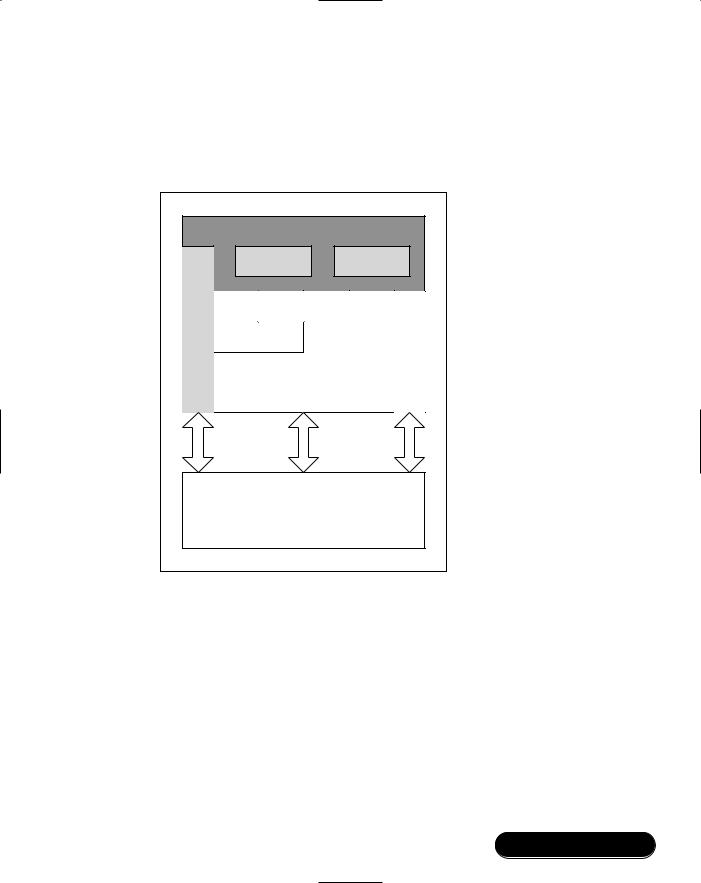
make sure that it supports the layers required for your application’s profiles. Figure 2.1 shows the layers defined by the Bluetooth specification (shown unshaded) and some other common layers (shown shaded).
Figure 2.1 Bluetooth Protocol Stack
|
Application |
|
|
|
|
Connection |
|
Security |
|
|
Manager |
|
Manager |
|
Manager |
OBEX |
|
|
|
|
TCS |
SDP |
|
|
RFCOMM |
|
|
|
|
Device |
|
|
Audio |
|
|
|
|
||
|
|
L2CAP |
|
|
Control |
HCI |
Data |
HCI |
Audio |
|
|
|||
Baseband:
Link Manager,
Link Controller
and Radio
L2CAP
Logical Link Control and Adaptation Protocol multiplexes upper layer data onto the single Asynchronous ConnectionLess (ACL) connection between two devices and, in the case of a master device, directs data to the appropriate slave. It also segments and reassembles the data into chunks that fit into the maximum HCI payload (the HCI is the Host Controller Interface, which connects higher layers on a host to lower layers on a Bluetooth device). Locally, each L2CAP logical channel has a unique Channel Identifier (CID), although this does not necessarily match the CID used by the remote device to identify the other end of the same channel. CIDs 0x0000 to 0x003F are reserved with 0x0000 being
www.syngress.com
72 Chapter 2 • Exploring the Foundations of Bluetooth
unused; 0x0001 carrying signaling information; and 0x0002 identifying received broadcast data.
Debugging…
Reliability of L2CAP
Because of the nature of wireless communications, the links provided by the baseband are not reliable. Errors are caused by radio interference or fading of signals. There is a chance that two or more errors in a packet will combine to give a packet that contains errors but still has a correct checksum. The Bluetooth Special Interest Group (SIG) is considering implementing error correction at L2CAP, which would make such errors less likely to affect applications.
The stack layers that sit above L2CAP can be identified by a Protocol Service Multiplexor (PSM) value. Remote devices request a connection to a particular PSM, and L2CAP allocates a CID.There may be several open channels carrying the same PSM data. Each Bluetooth defined layer above L2CAP has its own PSM:
■SDP – 0x0001
■RFCOMM – 0x0003
■Telephony Control Protocol Specification Binary (TCS-BIN) – 0x0005
■TCS-BIN-CORDLESS – 0x0007
L2CAP only deals with data traffic, not voice, and all channels, apart from broadcasts (transmissions from a master to more than one slave simultaneously), are considered reliable.
RFCOMM
RFCOMM (a name coming from an Radio Frequency [RF]-oriented emulation of the serial COM ports on a PC) emulates full 9-pin RS232 serial communication over an L2CAP channel. It is based on the TS 07.10 standard for a software emulation of the RS232 hardware interface.TS 07.10 includes the ability to multiplex several emulated serial ports onto a single data connection using a different
www.syngress.com

Exploring the Foundations of Bluetooth • Chapter 2 |
73 |
Data Link Connection Identifier (DLCI) for each port. However, each TS 07.10 session can only connect over a single L2CAP channel and thus only communicate with one device. A master device must have separate RFCOMM sessions running for each slave requiring a serial port connection.
Version 1.1 of the Bluetooth specification has added to the capabilities of the standard TS07.10 specification by providing flow control capabilities.This caters for mobile devices with limited data processing and storage capabilities allowing them to limit the incoming flow of data.
OBEX
The Object Exchange standard (OBEX) was developed by the Infrared Data Association (IrDA) to facilitate operations common to IR-enabled devices like personal digital assistants (PDAs) and laptops. Rather than develop a new standard, the Bluetooth SIG took OBEX largely as is, detailed a few specifics regarding Bluetooth implementation (e.g., making some optional features mandatory), and used it in the File Transfer, Synchronisation, and Object Push profiles. OBEX allows users to put and get data objects, create and delete folders and objects, and specify the working directory at the remote end of the link. IrDA has also provided formats for data objects, while the Bluetooth specification has adopted the vCard format for business card exchange and the vCal format for exchanging calendars.
PPP
The Point-to-Point Protocol (PPP) is the existing method used when transferring Transmission Control Protocol/Internet Protocol (TCP/IP) data over modem connections.The Bluetooth specification reuses this protocol in the local area network (LAN) Access Profile to route network data over an RFCOMM port.Work is already underway on a TCP/IP layer that will sit directly above L2CAP, bypassing and removing the overhead of PPP and RFCOMM.This work is hinted at in some areas of the specification, but in v1.1 PPP, is all that’s available.
TCS Binary
Telephony Control Protocol Specification Binary (TCS Binary, also called TCSBIN), is based on the International Telecommunication Union-Telecommunication Standardization Sector (ITU-T) Q.931 standard for telephony call control. It includes a range of signaling commands from group management to incoming
www.syngress.com

74 Chapter 2 • Exploring the Foundations of Bluetooth
call notification, as well as audio connection establishment and termination. It is used in both the Cordless Telephony and Intercom profiles.
SDP
The Service Discovery Protocol differs from all other layers above L2CAP in that it is Bluetooth-centered. It is not designed to interface to an existing higher layer protocol, but instead addresses a specific requirement of Bluetooth operation:
finding out what services are available on a connected device.The SDP layer acts like a service database.The local application is responsible for registering available services on the database and keeping records up to date. Remote devices may then query the database to find out what services are available and how to connect to them.The details of service discovery can be complex and are discussed further in Chapter 5, but each profile describes exactly what information should be registered with SDP based on the application implementation.
Management Entities
Device, Security, and Connection Managers are not protocol layers so much as function blocks.The Device Manager handles the lower level operation of the Bluetooth device.The Connection Manager is responsible for coordinating the requirements of different applications using Bluetooth channels and sometimes automating common procedures.The Security Manager checks that users of the Bluetooth services have sufficient security privileges.
HCI
The Host Controller Interface is not a software layer, but a transport and communications protocol that aids interoperability between different manufacturers’ solutions. It is not mandatory to use the HCI interfaces defined in the specification (Universal Serial Bus [USB]; RS232; or a simple Universal Asynchronous Receive Transmit [UART]), or indeed any HCI transport at all, if there are better solutions for your application.
Lower Layers
The lower layers (Radio Baseband, Link Controller, and Link Manager) format the over-air transmissions, handle error detection and re-transmission, and manage the links between devices.
Table 2.1 illustrates which profiles use which layers.
www.syngress.com

|
|
Exploring the Foundations of Bluetooth • |
Chapter 2 |
75 |
|||
Table 2.1 Stack Layer Requirements by Profile |
|
|
|
||||
|
|
|
|
|
|
|
|
|
Lower |
|
|
|
|
|
|
Profile |
Layers |
L2CAP |
SDP |
RFCOMM |
PPP OBEX |
TCS-Bin |
|
|
|
|
|
|
|
|
|
Service Discovery |
|
|
|
|
|
|
|
Application |
X |
X |
X |
|
|
|
|
Cordless |
|
|
|
|
|
|
|
Telephony |
X |
X |
X |
|
|
X |
|
Intercom |
X |
X |
X |
|
|
X |
|
Serial Port |
X |
X |
X |
X |
|
|
|
Headset |
X |
X |
X |
X |
|
|
|
Dial-up |
|
|
|
|
|
|
|
Networking |
X |
X |
X |
X |
|
|
|
FAX |
X |
X |
X |
X |
|
|
|
LAN Access |
X |
X |
X |
X |
X |
|
|
Generic Object |
|
|
|
|
|
|
|
Exchange |
X |
X |
X |
|
X |
|
|
Object Push |
X |
X |
X |
|
X |
|
|
File Transfer |
X |
X |
X |
|
X |
|
|
Synchronization |
X |
X |
X |
|
X |
|
|
|
|
|
|
|
|
|
|
Why Unconnected Devices Need to Talk
As mentioned in the Introduction, not all the details of operating a radio communication link can be hidden from the application by intervening software layers. Some of the basics of wireless communications will be exposed and it is essential to handle these functions correctly if operation is to be as seamless as Bluetooth proponents envisage.With wired connections, the user might check that two devices have the same type of physical interface port, that the ports support the same communications protocol, and that both devices run applications that can use this protocol to talk to each other. If all these checks are passed, the user might then plug a cable into the two ports and expect some useful communication.With Bluetooth devices, the user may not initially know that there are other Bluetooth devices nearby, so a method is required to find them.Then there is the Bluetooth equivalent of plugging in a cable: forming a connection.The checks on communications protocols and applications compatibility are actually done once a basic Bluetooth link is established.They are called service discovery.
www.syngress.com

76 Chapter 2 • Exploring the Foundations of Bluetooth
This is not a book about the details of Bluetooth radio operation, but a little knowledge about a few fundamental principles of the radio and baseband will greatly help you understand what application level decisions are key, why they are key, and how making the wrong decisions could lead to some very undesirable behavior.
First, it is important to understand that Bluetooth radios use a frequencyhopping scheme.When connected, the precise frequency for each hop is selected by a pseudorandom algorithm that depends on the master device’s clock and Bluetooth address. Slaves in a piconet synchronize on the master’s hopping pattern. However, when unconnected, there is no master to synchronize to. Bluetooth devices need a way to exchange a limited amount of data, allowing them to find and connect to each other before synchronizing on a common clock and Bluetooth address.
The procedure used to find devices is called inquiry, and the procedure used to connect to devices is called paging. In both cases, one device transmits and receives on special sequences of frequencies that are known to all devices.The other device needs to be listening for the transmissions—if a transmission is received correctly, it sends out a reply. Since it knows the sequences used for inquiry and paging, it can work out the correct frequency on which to send the reply.The key points are:
1.The application must place a device in a listening mode if it is to be found or connected to.The listening mode that allows a device to be found is called discoverable mode or inquiry scanning.The listening mode that allows a device to be connected is called connectable mode or page scanning.The terms discoverable and connectable are used at the user interface, and the terms inquiry scanning and page scanning are used within the software layers.
2.Whether finding or connecting, for communication to take place, one device must transmit on the frequency that the other is receiving on. This is done by the transmitter changing frequency quickly (1600 times a second) while the receiver changes frequency slowly (every 1.28 seconds).Their frequency hopping is not synchronized, so the procedure must last long enough for the two devices to collide on a frequency that isn’t subject to interference.This also introduces a random element to the procedure: how long they take before transmitting/receiving on the same frequency.
www.syngress.com

Exploring the Foundations of Bluetooth • Chapter 2 |
77 |
3.A Bluetooth device will not reliably find or connect to other devices at the same time as transferring voice.Voice links take priority over everything, while inquiry and page operations take precedence over other data transfers. It is allowed to inquire and page in the gaps between voice transmissions, but because the voice transmission takes priority, often responses will be lost due to a voice transmission, so finding and connecting devices can be slow and unreliable when voice links are in use.You must be aware of these limitations when deciding how your application will behave.
In the following sections, we will discuss the inquiry and page procedures in more detail.
Discovering Neighboring Devices
All Bluetooth devices must be discovered before a connection to them can be initiated.You may not need to carry out a device discovery every time you wish to connect to a device. Instead, you might be able to reuse information gathered from a previous device discovery.There must always be an initial device discovery before the connection, however.
There are two reasons to carry out device discovery. Either you do not know what devices are within range and wish to find out, or you know a device is within range and want to know its details so you can connect to it. In both cases, the procedure is the same and is called an inquiry.
Inquiring and Inquiry Scanning
To discover other nearby devices, a Bluetooth device conducts an inquiry.The basic command is HCI_Inquiry and has three parameters:
■Lower Address Part (LAP)
■Inquiry_Length The inquiry will time-out after this period. Note that this parameter is in 1.28s units.
■Number_Of_Responses If the number of responses given here is reached, then the inquiry will end before the Inquiry_Length period has elapsed.
The LAP determines the Inquiry Access Code (IAC) used in the transmitted ID message which listening devices respond to.
www.syngress.com

78 Chapter 2 • Exploring the Foundations of Bluetooth
Debugging…
Messaging across HCI
Some host stacks do not handle multiple simultaneous transactions across HCI. These protocol stacks will wait for one command to complete before sending the next. If you have one of these stacks, then the inquiry cancel command will not work: this is because the inquiry command will be allowed to run until the inquiry complete event returns from the lower layers. Only after the inquiry complete has been returned will the next command (inquiry cancel) be sent. This means that the inquiry cancel is sent after the inquiry has already completed, so the lower layers respond with an error message as they cannot cancel an inquiry which is not in progress.
This is a rare problem as few commercial stacks now available cannot handle multiple simultaneous HCI transactions. But if you find your HCI misbehaving, it is worth investigating whether your stack is one that queues up messages for simultaneous HCI transactions rather than sending them to the lower layers.
There is also the option for the application to use HCI_Periodic_Inquiry_Mode and configure the Bluetooth lower layers to conduct periodic inquiry procedures automatically.There are corresponding commands, HCI_Inquiry_Cancel and HCI_Exit_Periodic_Inquiry_Mode, which cancel the inquiry commands.
The listening mode for inquiry is called Inquiry Scan. Only devices in Inquiry Scan will respond to inquiries and then only to inquiries which contain the correct IAC.This has consequences for your application—you can hide from other devices by not enabling Inquiry Scan; a device which does this is in non-discoverable mode. Conversely, you are not guaranteed to find all Bluetooth devices in an
area because devices which are not inquiry scanning are effectively invisible. Placing a device in Inquiry Scan mode involves setting up the right param-
eters, then enabling the mode. HCI_Write_Inquiry_Scan_Activity is used to set up the scan duration and the interval between scans.
HCI_Write_IAC_LAP is used to define the IAC that the device will be listening for.There are currently only two valid IACs.The General IAC (GIAC), 0x9e8b33, is used by most devices, most of the time. It is the default, the common meeting place for all devices, and must be supported. Some devices may also sup-
www.syngress.com

Exploring the Foundations of Bluetooth • Chapter 2 |
79 |
port the Limited IAC (LIAC), 0x9e8b00, which can be used if you only wish to be discovered for a limited amount of time and in response to a specific event. Instructions and guidelines on their use are provided in the Bluetooth profiles.
The GIAC is most commonly used. All devices that scan will listen for this code.The Limited Inquiry Access Code (LIAC) could be used in crowded environments where many devices are answering inquiries and it can be difficult to select the desired device.The owners of a pair of devices can agree to temporarily put them into Limited Inquiry mode.They will then use the LIAC as well as the GIAC for a short period before automatically reverting back to using only the GIAC.The Generic Access Profile (GAP) mandates that any device listening for the LIAC must also scan for the GIAC. If the Bluetooth hardware supports it, both IACs can be listened for at the same time, in parallel. However, many hardware implementations can only listen for one IAC at a time, so the scanning must be done in series. In this case, it is the application’s responsibility to manage the time-slicing between IACs so that GAP requirements are met.
The Limited Inquiry Access facility has not proved popular so far since it requires user intervention at both ends of the link and tends to be seen as an unnecessary complication for the user.
HCI_Write_Scan_Enable is used to both enable and disable the Inquiry Scan mode.
If a device in Inquiry Scan responds to an inquiry this is reported, at the Inquiring device, by an HCI_Inquiry_Result event. It is not reported at the Inquiry Scanning device. In fact, the application is unaware that a response has been generated.The HCI_Inquiry_Result event is variable in length, depending on the number of responses, and has seven parameters:
■Num_Responses The number of responses being reported in this message.
■BD_ADDR The Bluetooth Device Address for each device responding.
■ |
Page_Scan_Repetition_Mode For each device responding. |
■ |
Page_Scan_Period_Mode For each device responding. |
■Page_Scan_Mode For each device responding.
■Class_Of_Device (CoD) CoD is a brief description of the type of device responding. Details are in Section 1.2 of the Bluetooth Assigned Numbers document. Again, there is one CoD for each responding device.
www.syngress.com

80Chapter 2 • Exploring the Foundations of Bluetooth
■Clock_Offset Since the hop frequency of the responding device is determined by its address and clock, information on the clock offset can be used to predict what frequency it will be listening on and reduce the time to connect to it. Again, one response for each device.
The Page_Scan parameters all refer to the frequency, intervals and exact method by which the scanning device allows other devices to connect to it. See the following section for more details.
Since both Inquiring and Inquiry Scanning devices randomly hop frequency, they may end up on the same frequency more than once during an inquiry procedure and several responses may be generated.Whether each response is reported by an HCI_Inquiry_Result event is dependent on the lower layer implementation and how many previous responses the lower layers can keep track of. The application must therefore be able to identify duplicate responses and filter them out.
When an inquiry is complete, because either the specified number of responses or duration has been reached, an HCI_Inquiry_Complete event is generated. It contains only a status parameter.
You can carry out inquiries or inquiry scans as an unconnected device, a master, or a slave. However, a slave’s responsibility to regularly listen for master transmissions means it will not be able to devote as much of it’s time to the procedure, which may need to continue for longer to compensate. It is also possible to define intervals and windows to allow both operations to run over the same period. See the next section on timing for more detail.
Timing
Since one device needs to be in Inquiry and the other in Inquiry Scan for a successful discovery, it is important for applications to give a high chance of finding devices in a short time.The Generic Access Profile offers guidelines on how to accomplish this. Devices that are generally discoverable (using the GIAC) repeatedly conduct a short inquiry scan over a long period of time while Inquiring devices conduct a long inquiry either once, upon user prompting, or periodically, but with a large interval in-between inquiries.
The actual numbers from the GAP are as follows:
■While discoverable, enter Inquiry Scan for at least 10.625 milliseconds every 2.65 seconds. Remain discoverable for at least 30.72 seconds.
■When inquiring, enter Inquiry mode for at least 10.24 seconds.
www.syngress.com

Exploring the Foundations of Bluetooth • Chapter 2 |
81 |
■For devices using the LIAC, it is not recommended to stay in Inquiry Scan mode for more than 1 minute.
If there are any voice links present, the data transfer required for them will take priority over both Inquiry and Inquiry Scan operations.You need to consider this when setting up the operations.
■If one HV3 Synchronous Connection Oriented (SCO) link is present, then the inquiry scan period should be extended to 22.5 milliseconds.
■If two HV3 SCO links are present (or one HV2 link), the inquiry scan period should be extended to 33.75 milliseconds.
These rules do not altogether compensate for the effect of SCO links, so you should still consider inquiry and paging procedures to be slower and less reliable if SCO links are in use.
It is often a good idea, if possible, to scale back voice connections to HV3 before entering Inquiry Scan. But note that with three HV3 links present, no inquiry scanning can take place at all: the device is non-discoverable (the same is applied to two HV2 links or one HV1 link; each of these configurations uses up all possible slots and leaves no space for inquiring or scanning).
The inquiry period must be increased to compensate for the presence of SCO connections, or being a slave, in the same way as the inquiry scan period. The Link Controller also makes appropriate changes to the sequence of inquiry transmission frequencies. Again, the presence of three SCO connections would prevent any other operations, including inquiry.
The Bluetooth profiles define which devices within a usage scenario should be discoverable and which should do the discovering.
When to Stop
In an ideal world, once you took the decision to be discoverable, other devices would be able to find you immediately, all the time. In the real world of Bluetooth devices, there are prices to be paid for that level of visibility: power consumption and bandwidth.
Power consumption explains why the default inquiry scan duty cycle is 0.4 percent. For some battery-powered devices, even this may be too high, so dropping into a non-discoverable state may be necessary to save power. Equally, if you are designing a mains-powered device, it may be desirable to increase the duty cycle and thus reduce the time it takes for other devices to find you.
www.syngress.com
82 Chapter 2 • Exploring the Foundations of Bluetooth
Although transfer of voice (SCO) data takes precedence over Inquiry Scan operations, other (ACL) data transfer does not. In other words, Inquiry Scan uses up bandwidth. If you have chosen a high Inquiry Scan duty cycle, you may need to reduce it, or even disable Inquiry Scan, to achieve a high data rate.
In all applications, there should be an option for the user to manually switch from a discoverable to a non-discoverable mode.The GAP also includes guidelines on how these modes should be described in the User Interface.
Inquiry operations are less problematic. Although the same principles apply as for Inquiry Scan (SCO data has higher priority, ACL data does not), the inquiry operation is normally a one off, and generally triggered by the user. If carrying out an inquiry is going to disrupt a critical data transfer, it might be a good idea to warn the user before proceeding. Automatic periodic scanning should be sensitive to bandwidth use if unexpected drops in transfer rates are to be avoided. Note that if the lower layers are set to periodically inquire, they will schedule inquiries with no allowances for data transfers: intelligent inquiry scheduling is only possible at the application level.The user should also be given the option of disabling periodic inquiry if the feature is offered.
One other consideration for inquiring devices is their effect on other ISM band users. Every inquiry transmission potentially interferes with another piconet, or even with other wireless technologies using the same frequencies as Bluetooth. So, by specifying short inquiry periods the GAP helps Bluetooth devices to be good neighbors, causing the minimum possible interference to nearby devices.
Connecting to a Device
Once a device has been discovered via inquiry, the information gathered can be used to form a Bluetooth connection between devices. At the Bluetooth Radio level, a connection means that the devices in a piconet are all frequency-hopping together, synchronized to the master device’s Bluetooth address and clock. Further up the protocol stack, it means that an ACL link has been established that data can pass over.This allows the use of L2CAP and all the other layers that sit above it, including the service discovery layer.The protocol for forming the link is called paging.
Paging and Page Scanning
To create a connection between Bluetooth devices one device pages another device, which must be in Page Scan to respond.The terms “create connection”
www.syngress.com

|
Exploring the Foundations of Bluetooth • Chapter 2 |
83 |
and “page” are often used interchangeably although the latter is more specific |
|
|
since connections can also be created between upper stack layers. A successful |
|
|
page results in an ACL connection between the paging device, which, by default, |
|
|
becomes the master, and the paged device, the slave. |
|
|
To allow an incoming connection, a device must be placed in Page Scan |
|
|
mode.This is similar to Inquiry Scan in that the mode must be configured, using |
|
|
the HCI_Write_Page_Scan_Activity, HCI_Write_Page_Scan_Mode, and |
|
|
HCI_Write_Page_Scan_Period_Mode, and then activated using the same |
|
|
HCI_Write_Scan_Enable command that controls the Inquiry Scan operation. |
|
|
Provided both modes have been configured with timing that allows it (see the fol- |
|
|
lowing), a device can be in both Inquiry and Page Scan modes at the same time. |
|
|
HCI_Write_Page_Scan_Activity sets the page scan period and the interval |
|
|
between scans, and hence the duty cycle. HCI_Write_Page_Scan_Mode determines if |
|
|
the device scans using the mandatory paging scheme or an optional one. Only one |
|
|
optional scheme is currently defined, although there is a provision for three. It is |
|
|
defined in Appendix VII of the Core Specification and trades an increased level of |
|
|
complexity and a higher duty cycle at the paging device for a lower duty cycle at |
|
|
the Page Scanning device. Few, if any, hardware vendors currently support the |
|
|
optional paging scheme, so a method must exist for hardware that doesn’t support |
|
|
it to connect to hardware that does. For this reason, devices in both Page and |
|
|
Inquiry Scan that receive an incoming inquiry must then use the mandatory paging |
|
|
scheme for Tmandatory_pscan seconds following. HCI_Write_Page_Scan_Period_Mode sets |
|
|
the number of seconds according to the Page Scan mode (see Table 2.2). |
|
|
Table 2.2 Relationship between SP Mode and Mandatory Page Scan Period |
|
|
|
|
|
Scan Period Mode |
Tmandatory_pscan |
|
P0 |
>20 seconds |
|
P1 |
>40 seconds |
|
P2 |
>60 seconds |
|
To initiate a page, an application issues an HCI_Create_Connection command that contains the following parameters:
■BD_ADDR The Bluetooth device address of the device you wish to page.
■Packet_Type The types of ACL packet the local device will support on this link (i.e. DH/M 1/3/5).
www.syngress.com

84 Chapter 2 • Exploring the Foundations of Bluetooth
■ Page_Scan_Repetition_Mode How often the target device enters Page Scan mode.
■Page_Scan_Mode Whether to use the mandatory Page Scan mode, or an optional mode.
■Clock_Offset The estimated difference between the local device’s clock and the target device’s clock.
■Allow_Role_Switch Determines whether the local device will accept a request from the target device to swap master/slave roles.
Apart from Packet_Type, the first five parameters are provided as part of an inquiry response.The BD_ADDR is required to identify the target device.The two Page_Scan parameters determine the exact baseband operation during the page. Knowing the Clock_Offset of a device is not essential to making a connec- tion—it can still be made if this value is completely wrong—but the better the estimate, the shorter the connection time.The paging device uses the BD_ADDR and Clock_Offset parameters to calculate the frequency the target device will be page scanning on and starts its paging transmission there. If initially unsuccessful, the paging device then tries other, progressively less-likely frequencies until eventually all possibilities have been covered.
When the target device receives an incoming page, it does not necessarily accept it immediately.The HCI_Set_Event_Filter command can be used to switch between three possible behaviors:
■Send an HCI_Connection_Request event to the host and wait for an
HCI_Accept_Connection_Request or an HCI_Reject_Connection_Request command.
■Accept the Page automatically.
■Accept the Page automatically only if the paging device accepts master/slave role switch.
The last is important for profiles such as LAN access where an access point is discoverable and connectable while being a master of a piconet. A new device, when it connects, becomes, by definition, the master.The new device must allow the role switch so that the access point can become a master again and continue to maintain communications with the existing slaves.
www.syngress.com

Exploring the Foundations of Bluetooth • Chapter 2 |
85 |
Developing & Deploying…
Masters, Slaves, Role Switches, and Scatternets
To upper stack layers, the only difference between a master and a slave is that a master can talk to several slaves in a piconet, while a slave can only talk to the master of the piconet.
For some devices, this relationship is important. Take, for example, a PC with a Bluetooth mouse and keyboard already operating. The PC may also wish to allow a PDA to connect and synchronize. Since the PDA initiates the connection, it becomes the master of the new piconet, but the PC will only have allowed this connection if, as part of the connection request, the PDA stated it allows master/slave role switches. As soon as the connection is established at baseband level, the PC requests a switch. If the PDA does not grant it, the PC drops the connection.
Interestingly, for the time between the connection completing and the role switch taking place, the PC is still master of its old piconet even though it’s a slave of the PDA’s piconet. When a single device is a master of one piconet, and slave of another simultaneously, this is, by definition, a scatternet.
Several manufacturers now support the limited form of scatternet required for a master/slave role switch while master of an existing piconet, but maintaining the scatternet for any length of time is still problematic. The Bluetooth specification gives no way for a slave to demand hold, sniff, or park modes from a master; they must always be requested. The master is entitled to refuse such requests, so it is impossible to guarantee that a slave in one piconet will be granted the time required to participate in another piconet as a master or a slave. Even if devices choose to simply switch between piconets as they see fit, ignoring the normal request procedures, there are still problems with how to time these switches in order to maintain multiple connections.
The master of each piconet must periodically poll all its slaves in order to give them an opportunity to transmit (since slaves only transmit data in response to a master transmission). How to cope with the variability of the interval between poll transmissions from a master is particularly awkward. It is possible to devise solutions to these problems, but there are a number of possible solutions and no guarantee that two implementers will choose the same one. A single chip set vendor may be able to demonstrate scatternet operation provided they produce all
Continued
www.syngress.com

86 Chapter 2 • Exploring the Foundations of Bluetooth
devices in the scatternet, but this provision goes against the fundamental Bluetooth concept of interoperability. Work is progressing in the Bluetooth SIG to devise a standard solution to these problems.
There is an even greater problem with SCO connections in a scatternet, however. The reserved slots for SCO connection in two scatternetconnected piconets are running on different clocks. They will eventually drift, relative to each other, so that the reserved slots coincide, making it impossible for a single device to be part of both piconets. There is no way to renegotiate the SCO timing once the link has been set up.
Fortunately, the problems with ACL scatternets may be resolved soon, but those of SCO scatternets will likely be around for a very long time. For the moment though, no profiles use, let alone require, scatternet operation.
If the page is successful, an HCI_Connection_Complete event is generated at both ends of the new link with a “Success” status and other parameters describing the connection.This includes the Connection Handle that, for a master with multiple slaves, is used to route data.A page can fail because it times out or is actively rejected in which case the paging device generates an HCI_Connection_Complete event with the appropriate “Failure” status parameter.
Timing
Many of the same principles that apply to inquiry also apply to paging.Where restrictions on inquiry timing are contained in the GAP, the core specification defines restrictions on page scanning.The restrictions on the length of each individual page scan, called the scan window, vary according to the number of SCO links present. SCO traffic has a higher priority than page operations, so the scan window must be extended to compensate for the lost bandwidth:
■If no SCO links are present, the scan window must be at least 11.25 milliseconds (ms).
■If an HV3 link is present, the scan window should be at least 22.4 ms.
■If two HV3 links (or an HV2 link) are present, the scan window should be at least 33.75 ms.
Restrictions are also placed on the period between page scans, called the scan interval.The maximum interval between the start of successive scans is 2.56 seconds. If page scanning is continuous (i.e., the scan window is the same length as
www.syngress.com

Exploring the Foundations of Bluetooth • Chapter 2 |
87 |
the scan interval), this is classed as Repetition Mode R0. If page scanning is not continuous, but the interval is less than 1.28 seconds, this is classed as Repetition Mode R1. Intervals between 1.28 seconds and the 2.56 second maximum are classed as Repetition Mode R2. A paging device alters the way it pages depending on the repetition mode of the target device, which is why this information is returned as part of an inquiry response and is a parameter of the
HCI_Create_Connection command.
There is little point in a device being discoverable via Inquiry Scan but not connectable. Although it is theoretically possible to place a device in Inquiry Scan, but not Page Scan, this mode of operation is not currently used by any profile. Most devices will be in Inquiry Scan and Page Scan at the same time.To do this, the two scan intervals should be set equal, with the scan periods each occupying a maximum of half the scan interval. Like Inquiry Scan, shorter scan intervals can be used to reduce power consumption.
If an inquiry has previously been performed, then there is no need to repeat the process every time a link between two devices is re-established. In fact, placing a device in Inquiry Scan unnecessarily wastes power and allows any other device within range to find it, generating unwanted inquiry responses.The Inquiring device may also attempt to connect—if only to check the device’s friendly name—wasting even more power. It is therefore common for devices to be in Page Scan only.This is especially true of devices, like headsets, that are bonded: linked securely to another device. One device of the bonded pair might go into Page Scan when powered on, and the other would page it.The information for the Page operation would come from a single inquiry when the devices first bonded.
As mentioned previously, how long is spent paging before a connection is established largely depends on how accurately the paging device knows the paged device’s Clock_Offset. If it is exact, then connecting can take as little as 4ms. However, when not in a link, devices’ offsets drift.The longer it has been since the last connection between two devices, the less accurate the offset information. It will take longer to connect next time. If one device has been powered off and on between connections, the offset information is useless: no better than a random guess. However, as long as the Bluetooth Address is correct, a connection will still be formed eventually.The theoretical worst-case duration for a page is just over five seconds. Interference or the presence of SCO links may extend this time.The timeout period is set by the HCI_Write_Page_Timeout command.The default is 5.12 seconds.
www.syngress.com

88 Chapter 2 • Exploring the Foundations of Bluetooth
Who Calls Who?
Many Bluetooth profiles don’t care which device is the master of a link and which is a slave. For a Point-to-Point Profile, the distinction is meaningless at the higher layers. However, the distinction should be considered, especially for bat- tery-powered devices, as it can have a huge effect on a device’s power consumption, for two reasons.
Take, for example, a PDA that wishes to periodically and unconsciously synchronize with a PC. Firstly, if by default, the PC initiates connections, then the PDA must be connectable at all times. Even with an average Page Scan current draw of 0.5 mA, it is still going to use 12 mA-hours of power per day just maintaining the Page Scan mode. It may be more efficient to have the PDA wake periodically and attempt to page the PC.
Secondly, although a slave can request power saving modes such as sniff and park, a master is under no obligation to grant them. If they are not granted, then a slave must listen for a master’s transmissions in every possible transmit slot, draining power each time. As a master, a device only needs to transmit enough to maintain a link and there is a better chance that power saving modes can be negotiated and used.
Finding Information on
Services a Device Offers
There are many different potential types of Bluetooth device, each with different possible combinations of supported profiles, some of which have not even been thought of yet. All these devices can connect and talk to each other, but they may not support compatible profiles. For example, a headset has little use for Internet access.When initial contact is made, the devices need to ask each other a question.The exact question depends on circumstances. It is a choice between either “Do you provide service X?” or “What services do you provide?”
The first question is appropriate when the device asking the question is only interested in a specific service. Our headset will only be interested in finding devices that can act as an audio gateway. It has no interest in LAN Access Points, so it will ask,“Do you provide an Audio Gateway service?”The second question would be asked, for example, by a PC that wishes to know what devices are in the neighborhood and what services they all provide.
www.syngress.com

Exploring the Foundations of Bluetooth • Chapter 2 |
89 |
The mechanism to ask and answer these questions is provided by the Service Discovery Protocol, a protocol for accessing a database of the services a device offers.The database also contains the information required to answer the subsequent question, “How do I use service X?” Since the application supplies the services, it is also responsible for maintaining accurate SDP records of them. Remote devices connect to the SDP server as clients and query these records.
A service discovery record contains a number of attributes drawn from 28 possible types.They describe six broad types of information:
■The services on offer (e.g., Generic Audio, Headset Audio Gateway, Handsfree Audio Gateway); their names, availability, and descriptions.
■The protocols used to access the services (e.g., L2CAP and RFCOMM).
■How to connect to these protocols (e.g., the RFCOMM port).
■The supported profiles (e.g., Headset, Handsfree).
■How the service browsing tree is constructed.
■The behavior of the database (e.g., when the service record is likely to change).
Attributes are identified by their own Universally Unique Identifiers (UUIDs).The ideas and mathematics of UUIDs are not unique to Bluetooth. They are designed so that users can generate their own UUIDs with such a low chance of two independently generated IDs being the same that this, in itself, is sufficient to ensure they are not repeated. No central register of new UUIDs needs to be kept. UUIDs in the range 0 to 232 are reserved for SIG-defined attributes, but others can be created by product manufacturers. New manufac- turer-created attributes will only be recognized by other products that already know how the related services and protocols work and will not, therefore, experience the high level of interoperability that SIG-defined services enjoy. New services must be different from SIG-defined services, or extensions to them.You are not allowed to create a service that is similar to a headset, but that isn’t interoperable with the Headset profile.
The construction of the service discovery record can be complicated, but it is essential if devices are going to interoperate correctly. Fortunately, a majority of attributes that an application should store in the database are exactly specified in each profile.
www.syngress.com
90 Chapter 2 • Exploring the Foundations of Bluetooth
Every service record browsing tree must have a root named PublicBrowseRoot. PublicBrowseRoot is required as all service browsing trees contain this entry as their root.The presence of PublicBrowseRoot means that all client devices have a known location where they can begin browsing.
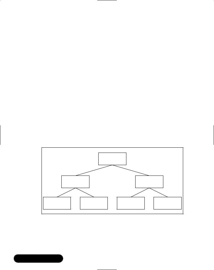
Apart from the requirement for a known root, the construction of the service record browsing tree is not defined by the profiles, but by the manufacturer. You should simply try to make the browsing tree logical. For example, a Global System for Mobile Communication (GSM) phone might offer the following services:
■Headset Audio Gateway
■Handsfree Audio Gateway
■Cordless Telephony
■Intercom
With the addition of the Generic Audio service group, Generic Telephony service group, and the PublicBrowseRoot entry, the service record browsing tree shown in Figure 2.2 can be constructed.
Figure 2.2 A Service Record Browsing Tree
|
|
PublicBrowseRoot |
|
|
|
Generic Audio |
|
Generic |
|
|
|
Telephony |
||
|
service group |
|
||
|
|
service group |
||
|
|
|
||
Headset |
Handsfree |
Cordless |
Intercom |
|
Audio Gateway |
Audio Gateway |
Telephony |
||
service |
||||
service |
service |
service |
||
|
To browse a remote device’s service discovery database, a local device must page and set up an ACL connection with it.This means that a device must be in Page Scan mode and accepting connections before information on the services it offers can be gathered. Once an ACL connection is formed, the local device must
www.syngress.com

Exploring the Foundations of Bluetooth • Chapter 2 |
91 |
then open an L2CAP channel and use the reserved PSM (0x0001) to request a connection to the SDP layer.This PSM never changes, and SDP is always present, so you always know where to look for information on a device’s services.The L2CAP connection can only be used for service discovery. If you wish to use other services, another L2CAP connection is required.This is important for maintaining security while still allowing service discovery to take place.
The process of service discovery is covered in detail in Chapter 5.
Connecting to and Using
Bluetooth Services
Several stages must be completed before you can use a Bluetooth service.
1.Find the device – Inquire.
2.Connect to the device – Page.
3.Discover what services the device supports – SDP.
4.Decide what service to connect to and find out how to connect to it – SDP.
5.Connect to the service.
Stages 3 thru 5 all involve connecting to more than one upper layer. Connections to these upper layers must each be opened separately and in order. The following figures illustrate this process for an Audio Gateway connecting to and setting up an audio link to a Headset.This is a conceptual summary, not a detailed systematic guide.The exact steps an Audio Gateway application will need to go through will depend on how much of the detail is abstracted by a Connection Manager.The following sections give one example sequence.
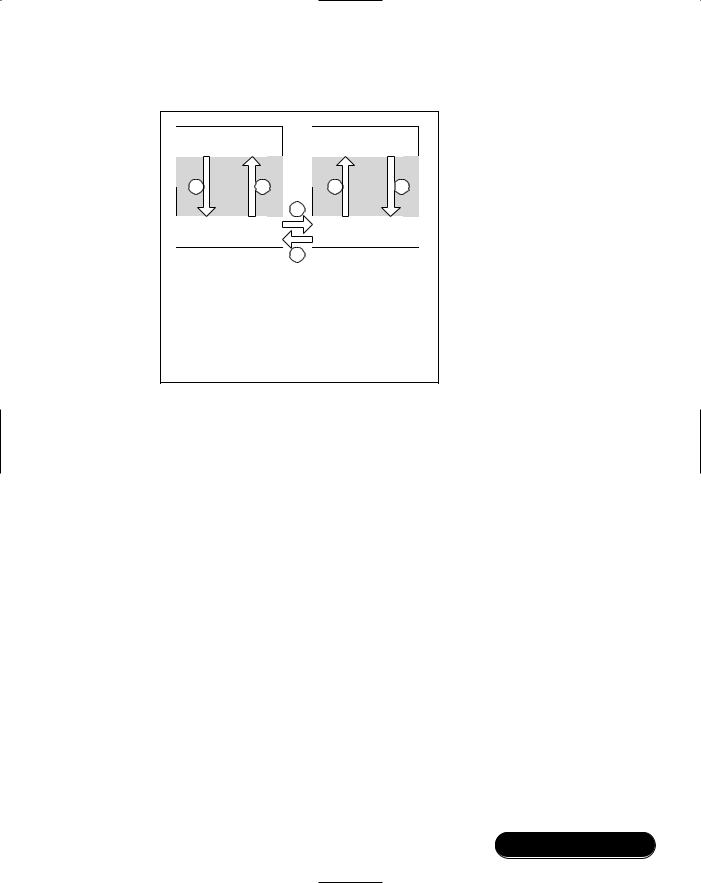
Stage 1: Finding the device by Inquiring. (See Figure 2.3.) These diagrams are simplified, and omit details of configuration. So, for instance it’s assumed that somehow the Audio Gateway has configured inquiry parameters, and that the Headset has been placed in Inquiry Scan mode.
1.The Audio Gateway application sends an inquiry request to the lower layers.
2.The lower layers send inquiry packets to the neighborhood.
3.All Inquiry Scanning devices in the neighborhood, including the headset, reply with inquiry responses.
4.The lower layers send the responses to the Audio Gateway application.
www.syngress.com
92 Chapter 2 • Exploring the Foundations of Bluetooth
Figure 2.3 Simplified Inquiry Procedure
|
AG Application |
|
|
Headset Application |
||
|
RFCOMM |
SDP |
Audio |
|
RFCOMM |
SDP |
|
1 |
4 |
|
|
Audio |
|
|
L2CAP |
|
|
L2CAP |
||
|
|
|
2 |
|
||
|
|
|
|
|
|
|
|
Baseband |
|
|
|
Baseband |
|
|
|
|
|
3 |
|
|
Inquiry |
|
|
|
|
|
|
1. |
Application starts inquiry |
|
|
|
||
2. |
Baseband inquiry |
|
|
|
|
|
3. |
Baseband inquiry response |
|
|
|
||
|
(Headset in Inquiry Scan) |
|
|
|
||
4. |
Inquiry result reported |
|
|
|
|
|
Note that the Headset application is not involved at all: once it has configured the lower layers to Inquiry Scan, it is completely unaware of any inquiry responses they generate.
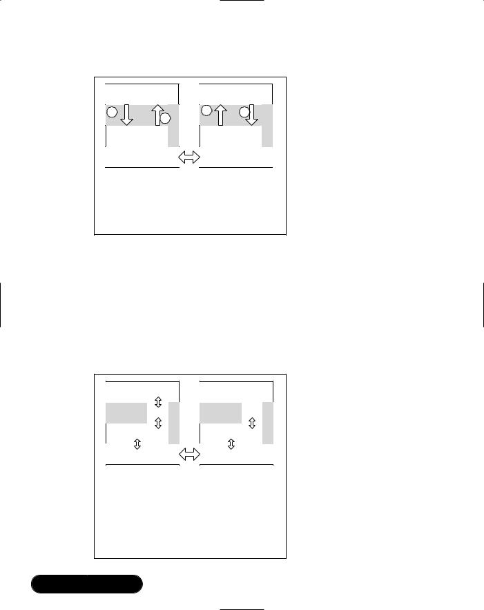
Stage 2: Connecting to the device by paging. (See Figure 2.4.) Again, these diagrams are simplified, and omit details of the configuration. So, for instance, it is assumed that somehow the Audio Gateway has configured Page parameters, and that the Headset has been set into Page Scan mode.
1.The Audio Gateway application sends a page request to the lower layers
2.The lower layers of the Audio Gateway page the Headset, using its Bluetooth device address to generate ID packets, which only it will be listening for. Other page scanning devices in the neighborhood will not detect the paging or respond to it. At this stage, a series of low-level packets are exchanged.The details are not important except to note that the Headset is passed information on the Audio Gateway device, including its Bluetooth device address and Class of Device.
3.The lower layers on the Headset send a message to the Headset application notifying it of the connection request.This notification will include the Audio Gateway’s Bluetooth device address and Class of Device, which were gathered during paging.
www.syngress.com
Exploring the Foundations of Bluetooth • Chapter 2 |
93 |
Figure 2.4 Simplified Page Procedure
AG Application
RFCOMM |
SDP |
1 |
6 |
L2CAP |
|
Baseband |
|
Page
Audio
Headset Application
RFCOMM SDP
3 |
4 |
L2CAP
2
Baseband
5
Audio
1.Application requests connection
2.Baseband page
3.Incoming connection request
(Headset not set up to auto-accept connections)
4.Accept connection
5.Baseband page response - connection accepted
6.Connection complete (ACL link in place)
4.The Headset application replies to the lower layers accepting the connection.
5.The lower layers on the headset send the response to the lower layers on the Audio Gateway.
6.The lower layers on the Audio Gateway forward the message, accepting the connection to the Audio Gateway application.The Audio Gateway application now knows it has an ACL (data) connection ready for use.
Stage 3: Discovering what service a device supports through SDP. (See Figure 2.5.) The first thing to do when connecting to SDP is establish an L2CAP connection using the PSM which identifies the SDP layer.
1.The Audio Gateway application sends a request to its local L2CAP layer asking for an L2CAP connection to the PSM for SDP on the Headset.
2.The request is relayed to the L2CAP layer on the Headset, which asks the Headset application if it is willing to accept the request.
3.The Headset application responds that it will accept a connection to the SDP layer.
4.The response is relayed to the L2CAP layer on the Audio Gateway, which informs the Audio Gateway application that an L2CAP connection to the SDP layer on the headset is available for use.
www.syngress.com
94 Chapter 2 • Exploring the Foundations of Bluetooth
Figure 2.5 Simplified L2CAP Connection to SDP Procedure
AG Application |
Headset Application |
1 |
RFCOMM |
4 |
|
2 |
RFCOMM |
3 SDP |
|
SDP |
Audio |
|
|
Audio |
|
|
L2CAP |
|
|
L2CAP |
||
|
|
|
|
|
ACL
Baseband |
Baseband |
Initialize L2CAP to SDP
1.AG requests connection to SDP (PSM 0x0001)
2.L2CAP connection request indication at Headset
3.Headset accepts connection
4.L2CAP CID for SDP connection is reported at AG
Stage 4: Decide what service to connect to and find out how to connect to it. (See Figure 2.6.) The Audio Gateway application can now send SDP requests and will receive SDP responses from the SDP server on the Headset. Notice that once the Headset application has registered a service record with the SDP layer, it does not need to be involved in SDP transactions—the SDP layer can respond to requests autonomously.
Figure 2.6 Simplified SDP Search Procedure
AG Application |
|
RFCOMM |
SDP |
L2CAP |
Audio |
|
|
|
ACL |
Baseband |
|
Headset Application |
|
RFCOMM |
SDP |
L2CAP |
Audio |
|
|
Baseband |
|
SDP Search
AG application uses SDP to discover services
offered by Headset application. Headset application should already have placed a correct service record in the database. Information returned includes PSM for RFCOMM and DLCI for RFCOMM channel.
Once information is gathered, SDP connection can be closed.
www.syngress.com
Exploring the Foundations of Bluetooth • Chapter 2 |
95 |
The Audio Gateway will send requests to retrieve the service record for the Headset Service.This checks that the service is really supported, and provides information on how to connect with it.
Stage 5: Connect to the service. (See Figure 2.7.) This stage begins in the same way as connecting to the SDP layer by creating an L2CAP connection.The procedures are exactly the same as those for creating an L2CAP connection to SDP, except that the PSM used this time is the PSM for RFCOMM.
Figure 2.7 Simplified L2CAP Connection to RFCOMM Procedure
AG Application |
Headset Application |
1 |
RFCOMM |
SDP |
4 |
|
2 |
RFCOMM |
3 |
SDP |
|
L2CAP |
|
|
Audio |
|
L2CAP |
|
Audio |
|
|
|
|
|
|
|
ACL
Baseband |
Baseband |
Initialize L2CAP to RFCOMM
1.AG requests connection to RFCOMM (PSM 0x0003)
2.L2CAP connection request indication at Headset
3.Headset accepts connection
4.L2CAP CID for RFCOMM connection is reported at AG
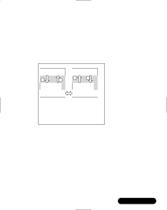
Once the L2CAP connection to RFCOMM is established, it can be used to carry messages between the Audio Gateway application and the Headset application. As we noted in “Reviewing the Protocol Stack,” RFCOMM can carry many emulated serial links simultaneously, therefore the Audio Gateway must identify the correct link to use to communicate with the Headset service.This is done by using the DLCI for the Headset service, which was passed to the Audio Gateway in the Headset’s service record. See Figure 2.8.
Once the Audio Gateway and Headset are communicating across RFCOMM, the Audio Gateway can send control messages using AT commands (the same command set that is commonly used to control modems). See Figure 2.9.To notify the Headset application that there is a call waiting, and to ask the headset application to alert the user with a ring tone, the Audio Gateway application sends an AT+RING command over the RFCOMM link. If the headset user
www.syngress.com

96 Chapter 2 • Exploring the Foundations of Bluetooth
presses a button to accept the call, the Headset sends this button press in a keypad command: AT+KPD.
Figure 2.8 Simplified L2CAP Connection to RFCOMM Procedure
AG Application |
||
RFCOMM |
SDP |
|
|
||
L2CAP |
Audio |
|
ACL |
||
|
||
Baseband |
|
|
Headset Application |
|
RFCOMM |
SDP |
|
|
L2CAP |
Audio |
|
|
Baseband |
|
RFCOMM Connection to Headset Service
AG uses RFCOMM channel with CID from SDP query to connect to Headset service and exchange control information.
Figure 2.9 Simplified Headset Service Connection Procedure
AG Application |
|
RFCOMM |
SDP |
|
|
|
Audio |
L2CAP |
ACL |
|
|
Baseband |
|
|
SCO |
Headset Application |
|
RFCOMM |
SDP |
|
Audio |
L2CAP |
|
Baseband |
|
Set Up Audio Connection
Control messages are exchanged over RFCOMM channel to open an audio connection.
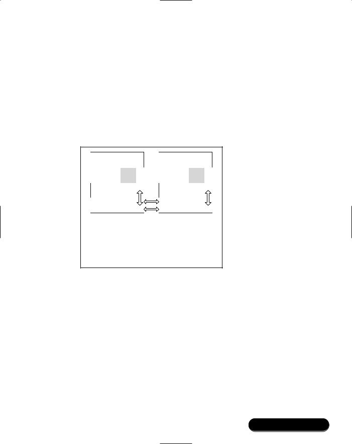
Once the user has accepted the call, a voice (SCO) link must be set up (see Figure 2.10). Although this link is controlled using the RFCOMM link, it is established separately, usually by a separate audio control layer. Once the SCO link is established, it is still controlled by the RFCOMM link. For instance, some headsets support remote volume control using AT commands, and the
www.syngress.com
Exploring the Foundations of Bluetooth • Chapter 2 |
97 |
SCO link can be destroyed by sending a hang-up command AT+HUP on the RFCOMM link.
The exact procedure for using the service is defined in the appropriate Bluetooth profile. As we have seen, the level of detail in a profile goes to the exact AT command to be sent over an RFCOMM channel when a particular button is pressed. It is this level of detail that allows such a high level of interoperability. Some procedures, such as those for a Headset, are relatively simple, while others are a lot more complex; the Printer Profile is a good example.
Figure 2.10 Simplified SCO Connection Procedure
AG Application |
|
RFCOMM |
SDP |
L2CAP |
Audio |
|
|
|
ACL |
Baseband |
|
|
SCO |
Headset Application |
|
RFCOMM |
SDP |
L2CAP |
Audio |
|
|
Baseband |
|
Audio Connection In Place
Although RFCOMM and L2CAP layers are still
active, they do not carry any audio data. (In Headset and AG devices, to reduce latency, audio is often routed over a PCM connection directly to and from the baseband rather than over the HCI transport.)
www.syngress.com

98 Chapter 2 • Exploring the Foundations of Bluetooth
Summary
The Bluetooth stack does a good job of hiding the complexities of a wireless interface, but some peculiarities are still apparent. Before connections can be made between devices, they must find each other. One device discovers another by sending out inquiry transmissions, while the other listens for these inquiries and replies to them. A device must be in Inquiry Scan mode to be discoverable. The specification details timing restrictions on Inquiry and Inquiry Scan designed to ensure that devices have the best chance possible of discovering each other, while still allowing a low duty cycle and hence, minimal power consumption. Increasing the duty cycle reduces latency, but increases power consumption.
Once two devices have found each other, they use a paging procedure to connect.This is similar to inquiry in that one device transmits while the other listens and then responds. Only devices that are in Page Scan mode can be connected to, but devices in Page Scan may reject an incoming connection request if they choose.The Bluetooth specification places limits on Page Scan to allow a good chance of connection while keeping power consumption low.
Devices are usually in Page Scan only (connectable but not discoverable), or Page and Inquiry Scan (connectable and discoverable).
While a Bluetooth service is being used, the complexities of the air interface are hidden by abstracting the interface across a number of software layers.The HCI transport provides a standardized interface to the Bluetooth integrated circuit (IC). Audio is routed directly over the HCI interface. Data traffic from several upper layers is multiplexed through the Logical Link Control and Adaptation Protocol (L2CAP), which identifies upper layer types by their Protocol Service Multiplexor (PSM) values.The actual L2CAP channels each have unique Channel Identifiers (CIDs).The Bluetooth specification describes several different types of layers above L2CAP, including RFCOMM for serial port emulation, and TSC-BIN for telephony profiles.
Different Bluetooth devices support different profiles and offer different services. Each Bluetooth application must maintain an accurate record of the services it offers in a service discovery database. Remote devices can then connect to this database and use the Service Discovery Protocol (SDP) to query it.The SDP layer can always be found in the same place, above L2CAP. Service discovery can be complex, but the Bluetooth profiles detail most of the attributes that should be stored in a service record.
www.syngress.com

Exploring the Foundations of Bluetooth • Chapter 2 |
99 |
Once a remote device has connected to a local device and found a service in the service database that it wants to connect to, attributes in the service record provide the information on the upper layers required to use the service and how to connect to them. Connections to each protocol layer must be made in turn from lowest to highest.
Solutions Fast Track
Reviewing the Protocol Stack
The protocol stack hides the complexity of the wireless interface and presents, at its highest level, a software interface that resembles that of a wired connection.
Not all the differences between a wired and a wireless interface can be hidden. In particular, the steps required to find and connect to other devices are peculiar to wireless.
Bluetooth devices can contain various combinations of upper stack layers to support various profiles.The Bluetooth specification details a service discovery layer so that devices can find out what services are available and how to connect to them.
Why Unconnected Devices Need to Talk
With Bluetooth devices, the user may not initially know that there are other Bluetooth devices nearby, so a method is required to find them. The Bluetooth equivalent of plugging in a cable is the forming of a connection.The checks on communications protocols and applications compatibility are actually done once a basic Bluetooth link is established, and are called service discovery.
The procedure used to find devices is called inquiry, and the procedure used to connect to devices is called paging. In both cases, one device transmits and receives on special sequences of frequencies that are known to all devices.The other device needs to be listening for the transmissions—if a transmission is received correctly, it sends out a reply. Since it knows the sequences used for inquiry and paging, it can work out the correct frequency on which to send the reply.
www.syngress.com

100 Chapter 2 • Exploring the Foundations of Bluetooth
Discovering Neighboring Devices
Only devices in Inquiry Scan can be discovered.
An inquiry is normally a periodic or user-initiated event.
An inquiry response contains all the information required to connect to a device by paging.
Connecting to a Device
Only devices in Page Scan can accept connections, although they may choose to reject incoming connection requests.
If a page and connection request is successful, then the paging device becomes the master of the piconet and the paged device becomes the slave. An Asynchronous ConnectionLess (ACL) connection now exists between the two.
A master can have connections to several slaves, but a slave can only have a connection to a master. For the upper stack layers, this is the only difference between the two.
Finding Information on Services a Device Offers
The application is responsible for maintaining accurate records of the services it offers in a service database.
An ACL and a Logical Link Control and Adaptation Protocol (L2CAP) connection must exist to a remote device before it can browse the service database using the Service Discovery Protocol (SDP).
The service database contains all the information required for a remote device to identify and connect to local Bluetooth services.
Connecting to and Using Bluetooth Services
A remote device must conduct an SDP query before connecting to a local Bluetooth service, and must support a complementary profile.
Connecting to a service involves first opening L2CAP, then higher layer connections in turn, using the information from the SDP query.
The procedure for using a service is detailed in the appropriate Bluetooth profile.
www.syngress.com

Exploring the Foundations of Bluetooth • Chapter 2 |
101 |
Frequently Asked Questions
The following Frequently Asked Questions, answered by the authors of this book, are designed to both measure your understanding of the concepts presented in this chapter and to assist you with real-life implementation of these concepts. To have your questions about this chapter answered by the author, browse to www.syngress.com/solutions and click on the “Ask the Author” form.
Q:I don’t like the way the Radio Baseband/Link Controller/Link Manager works. Can I change it?
A:No. Interoperability is a fundamental concept of the Bluetooth specification. If you change the way the lower layers function, they will no longer interoperate with other Bluetooth devices. In addition, several core technologies of the Bluetooth specification use Intellectual Property (IP) licensed from Ericsson, or the Bluetooth SIG (depending on which version of the adopter’s agreement you signed).The Bluetooth Adopters Agreement gives this license free of charge, provided your products meet the Bluetooth specification. If you change the operation, you would be breaking the specification, the free license would not apply, and you would be using IP without permission. Litigation may follow.
Q: I don’t like the way the upper layers work. Can I change them?
A:Yes, up to a point.You can create your own upper layers and profiles, provided the Generic Access Profile (GAP) is still met.The GAP mandates certain minimum functionality, including support for service discovery.This allows other Bluetooth devices to connect and find out what services are offered, even if the devices do not know how to use them: the responses are coherent and sensible. Support for SDP implies the presence of a specification compliant L2CAP layer. New profiles must be different from or extensions to current ones.You are not allowed to create something that is similar to the Headset profile, but will not interoperate with Bluetooth Headset Audio Gateways. However, any stack layer or profile functionality can only be used by an application that knows how it operates. Everyone can read how the Bluetooth specification defined layers and profiles work, so they experience a high degree of interoperability. Manufacturer defined layers and profiles will have a much lower visibility and a correspondingly lower level of interoperability.
www.syngress.com
102Chapter 2 • Exploring the Foundations of Bluetooth
Q:What is the difference between an L2CAP PSM value and an L2CAP CID?
A:Protocol Service Multiplexor (PSM) values identify the protocol used to communicate over an L2CAP channel. In effect, this defines the higher layer that uses the channel. Multiple instances of the same higher layer may use different L2CAP channels, but they will all be identified by the same PSM value. Each separate channel is uniquely identified by its Channel ID (CID). A higher layer may request an L2CAP connection to a remote RFCOMM entity by specifying a PSM value of 0x0003.The local and remote L2CAP layers then assign CIDs to this link.The CIDs are used to actually identify traffic sent between RFCOMM layers.
Q: What is the lowest power that a Bluetooth device can draw?
A:This question is only slightly less open-ended than “How long is a piece of string?”The absolute lowest power consumption will be when a device is not doing anything and can drop into a deep sleep mode. Many devices can do this when not part of an active connection; some can also do this in intervals between activity in low-power sniff, park, and hold modes. If low power modes are not used, then slaves can often draw more current than masters, since slaves have to listen in every possible slot for a master’s transmission, while masters only have to transmit when they need to. Although page scanning draws a lot less continuous current than paging, if paging is only to be an infrequent activity, the paging device may end up drawing less average current than a device in constant Page Scan mode. In summary, current consumption depends on the mode of device operation, which is determined by the application design. Power consumption implications should therefore be considered carefully when the application is designed. If an application is to be a good neighbor, it should also permit as much flexibility for devices that connect to it as possible (e.g., accept low power mode requests).The actual power consumption during each mode of operation will depend on the Bluetooth hardware implementation.
www.syngress.com