

IrWW_P2_V1p0
.pdfIrWW Time Synchronization Profile, Version 1.0 |
IrWW SIG |
Push Server – The device that provides an object push server. The Push Server receives Time-Sync object, which is used to synchronize the time with the client.
Push Client – The device that pushes Time-Sync object to the Push Server.
Time-Related objects are used to synchronize the time-related data, such as alarm, timer and stopwatch, between the Push Server and the Push Client as well as Time-Sync object.
3.2.2 Protocol Stack
Application |
|
|
|
Application |
|
Client |
|
|
|
Server |
|
|
|
|
|
|
|
Ultra |
|
|
|
Ultra |
|
IrWW |
|
IrWW |
|
||
|
|
|
|
|
|
Ultra |
Ultra |
||||
|
|
|
|
|
|
(IrLMP) |
|
|
|
(IrLMP) |
|
|
|
|
|
||
|
|
|
|
|
|
(IrLAP) |
|
|
|
(IrLAP) |
|
|
|
|
|
||
|
|
|
|
|
|
IrDA Hardware |
|
|
|
IrDA Hardware |
|
|
|
|
|
||
|
|
|
|
|
|
Push Client Side |
Push Server Side |
||||
IrDA Hardware is governed by the [IrPHY]
IrLAP is the link level protocol specified in [IrLAP].
IrLMP is a multiplexing layer specified in [IrLMP]
Ultra is connectionless protocol specified in [Ultra]
Ultra IrWW is placed on the upper layer Ultra protocol. Specified in [Ultra]
Application Client and Application Server are the application entities, which provide the user interface and perform the operation of the Time Synchronization profile.
3.2.3 Conformance
If conformance to this profile is claimed, all capabilities indicated mandatory for this profile shall be supported in the specified manner. This also applies for all optional and conditional capabilities for which support is indicated.
IrWW SIG |
5 |
IrWW Time Synchronization Profile, Version 1.0 |
IrWW SIG |
3.3 User Interface Aspects
3.3.1 Mode Selection(Server)
Push Server Mode is the state in which a Server is ready to receive an object from a Push Client.
It is mandatory that a Push Server be in this mode whenever the physical IR port is enabled (the IR port is able to receive signals). In some devices the IR port is enabled whenever the device is turned on. For other devices the user must explicitly turn on the IR port. Turning on the IR port must correspond to entering Server Mode.
3.3.2 Function Selection(Client)
The Push Function initiates the sending of an object to a Push Server.
3.3.3 Application Usage
When the user wants to send Time-Sync object or Time-Related object from a Push Client to a Push Server for synchronization, the following scenario can be followed.
Push Client |
Push Server |
||
|
|
|
|
|
|
|
The user sets the device into Push |
|
|
|
Server Mode if it is not already. |
The user of the Push Client selects |
|
|
|
the object to send. |
|
|
|
|
|
|
|
The user points the IR port of the |
|
|
|
Push Client device at the IR port of |
|
|
|
the Push Server device. |
|
|
|
The user selects the Push Function |
|
|
|
to send the selected object. |
|
|
|
|
|
|
|
|
|
|
When received, the Push Server |
|
|
|
immediately synchronizes its own |
|
|
|
time, alarm, timer or stopwatch using |
|
|
|
the received object. |
|
|
|
It is recommended that the user be |
|
|
|
notified of the success of the |
|
|
|
operation. |
IrWW SIG |
6 |
IrWW Time Synchronization Profile, Version 1.0 |
IrWW SIG |
3.4 Application Layer
3.4.1 Feature Overview - Basic Concept of Time Synchronization -
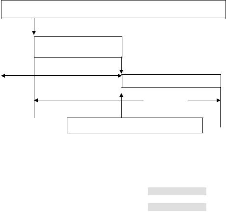
Time synchronization is regarded as the most important application. But highly accurate time synchronization result is required. In general, it is necessary to synchronize watches to accuracy of 10 ms or less. In order to guarantee highly accurate time synchronization, it is necessary to minimize transmission delay. If following sequence is carried out, delay time can be minimized.
1)When periodic interrupt signal, that is generated every one second, is received, timer data is captured and set to current time buffer.
2)An object frame is generated in which the current time data is involved.
3)The object frame is transmitted to a receiver right after process 2) is over.
The period between the beginning of process 1) and the end of process 3) correspond to delay time for time synchronization. Figure 1 depicts schematic of the process.
If the delay time is estimated, the sender can transmit estimated delay time as well as current time. And the receiver can compensate the current time with the delay time.
To precisely estimate delay time, it is necessary to eliminate unpredictable time loss that happens during above process. Time loss often occur in the transition from process 2) to process 3), if each process is implemented as independent task.
Taking into account the condition above, a protocol in which transmitting process is carried out immediately after framing process is suitable for time synchronization. Ultra protocol satisfies above requirement and accuracy of 104 microseconds is expected.
Tick Timer Generator
Periodic Interrupt
Generate frame
Receive interrupt
Transmit Frame
Delay Time
Unpredictable time-loss should be avoided.
Figure 1 Time Synchronization Concept
A device following this profile must be a Push Client, Push Server or both. Table 2 below shows objects in this profile. Time-Sync object must be supported.
Object |
Push Client |
Push Server |
Time-Sync |
M |
M |
Alarm |
O |
O |
Timer |
O |
O |
Stopwatch |
O |
O |
Table 2 Objects
IrWW SIG |
7 |
IrWW Time Synchronization Profile, Version 1.0 |
IrWW SIG |
3.4.2 Content Types
To achieve application level interoperability, content formats are defined for synchronization. The content formats are dependent on key application classes.
3.4.3 Time-Sync Object
Content format of the Time-Sync object is specified in [GBO].
Following is an example of the Time-Sync object written down with character strings.
(1)BEGIN: bWATCH
(2)VERSION:1.0
(3)BEGIN:T-Sync
(4) |
DATE;TYPE=VDYMDW:value |
…Mandatory |
(5) |
TIME;TYPE=VTHMSL:value |
…Mandatory |
(6) |
UTCOFFSET:value(VTUTC) |
…Mandatory |
(7) |
PTIME;TYPE=VTRL:value |
…Mandatory |
(8) |
REFERENCE:RTIME;RTYPE |
…Mandatory |
(9)END:T-Sync
(10)END:bWATCH
In the particular watches which have world time ability, UTCOFFSET property is used to indicate the time zone explicitly. In this case, local time data is transmitted in DATE and TIME properties with UTCOFFSET value. The watches not having world time ability transmit time data with 0xFF value in UTCOFSET property. In line (7), delay time is defined. And REFERENCE property is added to give receiver information about source of transmitted time. All properties are defined mandatory.
And the object translated into GBO format for Ultra IrWW Protocol. Table 3 shows Time-Sync object and corresponding GBO Time-Sync object for Ultra IrWW. OID for Time-Sync is 0x00 and mandatory properties are set in order. This example occupies 55 of 60 Bytes in the Ultra IrWW payload capability (refer to [Ultra IrWW] ).
OID |
0x00 |
|
|
|
|
|
|
|
|
DATE:TYPE=VDYMDW:value |
0x28 |
0x10 |
0x30 |
0x09 |
0x01 |
0x89 |
0x05 |
99999 |
0x00 |
TIME;TYPE=VTHMSL:value |
0x20 |
0x10 |
0x30 |
0x03 |
0x01 |
0x83 |
0x06 |
999999 |
0x00 |
UTCOFFSET:value |
0x24 |
0x01 |
0x8c |
0x02 |
99 |
0x00 |
|
|
|
PTIME;TYPE=VTRL:value |
0x21 |
0x10 |
0x30 |
0x06 |
0x01 |
0x86 |
0x03 |
999 |
0x00 |
REFERENCE:RTIME;RTYPE |
0x40 |
0x01 |
0x20 |
0x01 |
0x01 |
0x20 |
0x01 |
0x02 |
0x00 |
Table 3 Time-Sync Object example for Ultra IrWW
3.4.4 Alarm Object
Content format of Alarm Object is specified in [GBO].
Following is an example of the Alarm Object written down with character strings.
1)BEGIN : BWATCH
IrWW SIG |
8 |

IrWW Time Synchronization Profile, Version 1.0 |
IrWW SIG |
2)VERSION:1.0
3)BEGIN : ALARM
4) |
DATE;TYPE= VDYMDW:value |
…Mandatory |
5) |
TIME;TYPE=VTHM:value |
…Mandatory |
6)UTCOFFSET:value
7)CATEGORY:OTHER
8)ACTIVE:ON
9)ACTION;TYPE=SOUND:(value)
10)NOTE:value
11)END ALARM
12)END BWATCH
DATE (year/month/day/week type) and TIME (hour/minute type) are minimum set of property for alarm set. So, these two are defined mandatory.
UTCOFFSET: This property is used to indicate the time zone explicitly. If this property is ignored, Date and time is regarded as local time.
CATEGORY: This property indicates for what purpose the alarm is used. If this property is ignored, default CATEGORY; OTHER is set.
ACTIVE: This property define whether this function is activated in the receiver device or not. The purpose of this function is to let the owner of the receiver know the specified time. So default value of this property should be ON. Also it is recommended that when sending this object, ACTIVE parameter should be set to ON or ACTIVE parameter should not be described.
ACTION: This property specifies function to be carried out at the target time. There are three property parameters; DISPLAY, SOUND and VIBRATION that are basic functions for watch. More than one function can be listed. If this property is ignored, default function of the receiver watch is activated.
NOTE: By using this property, short message can be inserted. By setting this property, Alarm object can be utilized as simple schedule or to do event.
And the object translated into GBO format for Ultra IrWW Protocol. Table 4 shows Alarm Object and the corresponding GBO Alarm Object for Ultra IrWW. OID for Alarm is 0x10 and mandatory properties are set in order. Any other optional properties can be put at random following the mandatory properties until the object size will be 60Bytes. The object size is 24 Bytes in this example, 36 Bytes are available for optional properties.
OID |
0x10 |
|
|
0x09 |
|
|
|
|
|
DATE:TYPE=VDYMDW:value |
0x28 |
0x10 |
0x30 |
0x01 |
0x89 |
0x05 |
99999 |
0x00 |
|
TIME;TYPE=VTHM:value |
0x20 |
0x10 |
0x30 |
0x01 |
0x01 |
0x81 |
0x02 |
99 |
0x00 |
Table 4 Alarm Object example for Ultra IrWW
3.4.5 Timer Object
Content format of Timer Object is specified in [GBO].
Following is an example of the Timer Object written down with character strings.
1)BEGIN : BWATCH
2)VERSION:1.0
3)BEGIN : TIMER
4) |
PTIME;TYPE=VTHMS:value |
…Mandatory |
5) |
REPEAT:ON |
…Mandatory |
IrWW SIG |
9 |

IrWW Time Synchronization Profile, Version 1.0 |
IrWW SIG |
6)NOTE:value
7)END : TIMER
8)END : BWATCH
Type of the PTIME property in this case is hour/minute/second.
REPEAT: The device can repeat time count continuously when the status of this property is on. REPEAT is generic function of the timer.
And the object translated into GBO format for Ultra IrWW Protocol. Table 5 shows Timer Object and the corresponding GBO Timer Object for Ultra IrWW. OID for Timer is 0x20 and mandatory properties are set in order. Any other optional properties can be put at random following the mandatory properties until the object size will be 60Bytes. The object size is 19 Bytes in this example, 41 Bytes are available for optional properties.
OID |
0x20 |
|
|
|
|
|
|
|
|
PTIME;TYPE=VTHMS:value |
0x21 |
0x10 |
0x30 |
0x02 |
0x01 |
0x82 |
0x03 |
999 |
0x00 |
REPEAT:ON |
0x52 |
0x10 |
0x20 |
0x01 |
0x01 |
0x00 |
0x00 |
|
|
Table 5 Timer Object example for Ultra IrWW
3.4.6 Stopwatch Object
Content format of Stopwatch Object is specified in [GBO] .
Following is an example of the Stopwatch Object written down with character strings.
1)BEGIN : BWATCH
2)VERSION:1.0
3)BEGIN : STOPWATCH
4)DATE;TYPE=VDYMDW:value
5) |
PTIME;TYPE=VTHMSL:value |
…Mandatory |
6)NOTE:value
7)END : STOPWATCH
8)END : BWATCH
DATE property has year/month/day/week type value.
Type of the PTIME property in this case is hour/minute/second/under-second and only PTIME property is defined mandatory.
And the object translated into GBO format for Ultra IrWW Protocol. Table 6 shows Stopwatch Object and the corresponding GBO Stopwatch Object for Ultra IrWW. OID for Stopwatch is 0x30 and mandatory properties are set in order. Any other optional properties can be put at random following the mandatory properties until the object size will be 60Bytes. The object size is 15 Bytes in this example, 45 Bytes are available for optional properties.
OID |
0x30 |
|
|
0x03 |
|
|
|
|
|
PTIME;TYPE=VTHMSL:value |
0x21 |
0x10 |
0x30 |
0x01 |
0x83 |
0x06 |
999999 |
0x00 |
Table 6 Stopwatch Object example for Ultra IrWW
IrWW SIG |
10 |
IrWW Time Synchronization Profile, Version 1.0 |
IrWW SIG |
3.5 Ultra IrWW
Ultra IrWW is based on Ultra Protocol specified in [Ultra].
IrDA IrWW Devices must follow the recommendation in the Ultra specification that limits the maximum service data field size to 62 octets in length. Connectionless service is thus limited to use frames with maximum payload size of 60 octets.
OID specifies IrWW objects that are transferred with Ultra protocol. Unique number is given to each object.
Object |
OID |
Time-Adjust |
0x00 |
Alarm |
0x10 |
Timer |
0x20 |
Stopwatch |
0x30 |
Table 7 IrWW Object ID
The details of Ultra IrWW are described in [Ultra IrWW].
3.6 Ultra Protocol
PID is protocol ID of the high rank layer using ultra protocol. 0x01 is reserved for Ultra-OBEX currently. And 0x02 is reserved for Ultra-IrWW.
|
PID Octet |
|
|
|
|
PID No |
|
Function |
|
|
|
0x00 |
|
Reserved |
0x01 |
|
For Ultra OBEX |
0x02 |
|
For Ultra IrWW |
0x03 – 0x7f |
|
TBD |
MSB(bit 7) |
|
For extention |
Note: All PID values are reserved and assigned by IrDA.
Table 8 The PID Octet Encoding
In the Ultra IrWW, object data size is less than 60bytes so that communication procedure should be completed with one UI frame. Therefore, SAR is always set to 00h, and Ultra IrWW Frame consists of only one frame.
The details of Ultra Protocol are described in [Ultra].
3.7 IrLMP
A device must support connectionless LSAP(both DLSAP and SLSAP are 0x70), and the data packet must be delivered to the upper layer transparently.
IrWW SIG |
11 |
IrWW Time Synchronization Profile, Version 1.0 |
IrWW SIG |
3.8 IrLAP
The data packet must be delivered to IrLMP or upper layer.
3.9 Physical Layer
Devices are allowed to support the short-range option as described in [IrPHY]
IrWW SIG |
12 |
IrWW Time Synchronization Profile, Version 1.0 |
IrWW SIG |
4 ANNEX: Time Synchronization Profile for Legacy PC/PDA
4.1 User Requirements
4.1.1 Scope
The Time Synchronization profile (Connection-based) defines the requirements for the protocols and procedures that shall be used by applications implementing the Time Synchronization usage model. The most common devices implementing this usage model include PCs and PDAs.
4.1.2 User Scenarios
The scenarios covered by this profile are:
Usage of an IrDA device to synchronize the time with another IrDA device by using Time-Sync object. Usage of an IrDA device to synchronize the time-related data with another IrDA device by using TimeRelated object.
Object Type |
Format |
Examples |
|
|
|
Time-Sync Object (CO) |
BWATCH 1.0 |
Time |
|
|
|
Time-Related Object (CO) |
BWATCH 1.0 |
Alarm, Timer, Stopwatch |
|
|
|
Note: (CO) is Connection-Oriented Protocol.
Table 1 Objects for Time Synchronization Profile
4.2 Profile Overview
4.2.1 Configuration and Roles
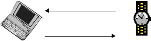
Pull Time-Sync object
Read time-related objects
Client Write time-related objects Server
Figure 2 Time Synchronization Example between wristwatch and PC
The following roles are defined for this profile.
Server – The device provides an object exchange server to and from which data objects can be pushed and pulled. The Server waits passively for the client to initiate the operation.
Client – The device can push or/and pull data objects to and from the server.
4.2.2 Protocol Stack
IrWW SIG |
13 |
IrWW Time Synchronization Profile, Version 1.0 |
IrWW SIG |
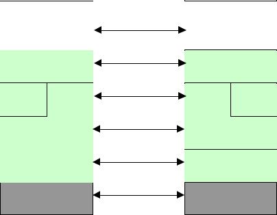
Application
Client
OBEX
Tiny |
IAS |
TP
IrLMP
IrLAP
IrDA Hardware
Application
Server
OBEX
Tiny |
IAS |
TP
IrLMP
IrLAP
IrDA Hardware
Client Side |
Server Side |
IrDA Hardware is governed by the [IrPHY]
IrLAP is the link level protocol specified in [IrLAP].
IrLMP is a multiplexing layer specified in [IrLMP]
Tiny TP provide flow control and is specified in [TINYTP]
IAS is the Information Access Service specified in [IrLMP]
OBEX includes both a session level protocol and an application framework. Both are specified in [OBEX]
Application Client and Application Server are the application entities, which provide the user interface and perform the operation of the Time Synchronization profile. They are discussed later in this document.
4.2.3 Conformance
If conformance to this profile is claimed, all capabilities indicated mandatory for this profile shall be supported in the specified manner. This also applies for all optional and conditional capabilities for which support is indicated.
IrWW SIG |
14 |