

Furber S.ARM system-on-chip architecture.2000
.pdfData processing instructions |
119 |
5.7Data processing instructions
Binary encoding
Description
The ARM data processing instructions are used to modify data values in registers. The operations that are supported include arithmetic and bit-wise logical combinations of 32-bit data types. One operand may be shifted or rotated en route to the ALU, allowing, for example, shift and add in a single instruction.
Multiply instructions use different formats, so these are considered separately in the next section.
register shift length -Figure 5.6
Data processing instruction binary encoding.
The ARM data processing instructions employ a 3-address format, which means that the two source operands and the destination register are specified independently. One source operand is always a register; the second may be a register, a shifted register or an immediate value. The shift applied to the second operand, if it is a register, may be a logical or arithmetic shift or a rotate (see Figure 3.1 on page 54), and it may be by an amount specified either as an immediate quantity or by a fourth register.
The operations that may be specified are listed in Table 5.4 on page 120.
When the instruction does not require all the available operands (for instance MOV ignores Rn and CMP ignores Rd) the unused register field should be set to zero. The assembler will do this automatically.
120 |
The ARM Instruction Set |
Table 5.4 ARM data processing instructions.
Opcode |
Mnemonic |
Meaning |
Effect |
|
124:21) |
|
|||
0000 |
AND |
Logical bit-wise AND |
Rd:=RnANDOp2 |
|
0001 |
EOR |
Logical bit-wise exclusive OR |
Rd := Rn EOR Op2 |
|
0010 |
SUB |
Subtract |
Rd := Rn - Op2 |
|
0011 |
RSB |
Reverse subtract |
Rd := Op2 - Rn |
|
0100 |
ADD |
Add |
Rd := Rn + Op2 |
|
0101 |
ADC |
Add with carry |
Rd := Rn + Op2 + C |
|
0110 |
SBC |
Subtract with carry |
Rd := Rn - Op2 + C - 1 |
|
0111 |
RSC |
Reverse subtract with carry |
Rd := Op2 - Rn + C - 1 |
|
1000 |
TST |
Test |
ScconRnANDOp2 |
|
1001 |
TEQ |
Test equivalence |
Sec on Rn EOR Op2 |
|
1010 |
CMP |
Compare |
Sec on Rn - Op2 |
|
1011 |
CMN |
Compare negated |
Sec on Rn + Op2 |
|
1100 |
ORR |
Logical bit-wise OR |
Rd := Rn OR Op2 |
|
1101 |
MOV |
Move |
Rd := Op2 |
|
1110 |
BIC |
Bit clear |
Rd:=RnANDNOTOp2 |
|
1111 |
MVN |
Move negated |
Rd:=NOTOp2 |
|
|
||||
|
|
|
|
|
These instructions allow direct control of whether or not the processor's condition codes are affected by their execution through the S bit (bit 20). When clear, the condition codes will be unchanged; when set (and Rd is not r15; see below):
•The N flag is set if the result is negative, otherwise it is cleared (that is, N equals bit 31 of the result).
•The Z flag is set if the result is zero, otherwise it is cleared.
•The C flag is set to the carry-out from the ALU when the operation is arithmetic (ADD, ADC, SUB, SBC, RSB, RSC, CMP, CMN) or to the carry-out from the shifter
otherwise. If no shift is required, C is preserved.
•The V flag is preserved in non-arithmetic operations. It is set in an arithmetic operation if there is an overflow from bit 30 to bit 31 and cleared if no overflow occurs. It has significance only when an arithmetic operation has operands that are viewed as 2's complement signed values, and indicates a result that is out of range.
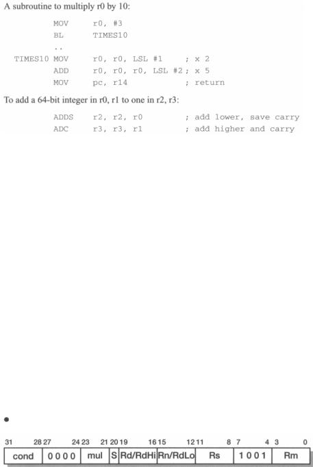
Multiply by a
constant These instructions may be used to multiply a register by a small constant much more efficiently than can be achieved using the multiply instructions described in
the next section. Examples are given below.
122 |
The ARM Instruction Set |
Notes |
1. Since the immediate field must be encoded within a subset of a 32-bit instruction, |
|
not all 32-bit immediate values can be represented. The binary encoding shown |
|
in Figure 5.6 on page 119 shows how the immediate values are encoded. The |
|
immediate value is generated by rotating an 8-bit immediate field through an |
|
even number of bit positions. |
5.8 Multiply instructions
ARM multiply instructions produce the product of two 32-bit binary numbers held in registers. The result of multiplying two 32-bit binary numbers is a 64-bit product. Some forms of the instruction, available only on certain versions of the processor, store the full result into two independently specified registers; other forms store only the least significant 32 bits into a single register.
In all cases there is a multiply-accumulate variant that adds the product to a running total and both signed and unsigned operands may be used. The least significant 32 bits of the result are the same for signed and unsigned operands, so there is no need for separate signed and unsigned versions of the 32-bit result instructions.
Binary encoding
Figure 5.7 Multiply instruction binary encoding.
Multiply instructions |
|
123 |
||
|
|
Table 5.5 Multiply instructions. |
|
|
|
|
|
|
|
Opcode |
Mnemonic |
Meaning |
Effect |
|
[23:21] |
|
|||
000 |
MUL |
Multiply (32-bit result) |
Rd:=(Rm*Rs)[31:0] |
|
001 |
MLA |
Multiply-accumulate (32-bit result) |
Rd:=(Rm*Rs + Rn)[31:0] |
|
100 |
UMULL |
Unsigned multiply long |
RdHirRdLo := Rm * Rs |
|
101 |
UMLAL |
Unsigned multiply-accumulate long |
RdHi: RdLo += Rm * Rs |
|
110 |
SMULL |
Signed multiply long |
RdHi:RdLo := Rm * Rs |
|
111 |
SMLAL |
Signed multiply-accumulate long |
RdHi:RdLo+=Rm*Rs |
|
|
|
|
|
|
Description
Assembler formats
The functions of the various forms of multiply are listed in Table 5.5. The notation used in the table is as follows:
•'RdHi:RdLo' is the 64-bit number formed by concatenating RdHi (the most sig nificant 32 bits) and RdLo (the least significant 32 bits).'[31:0]' selects only the least significant 32 bits of the result.
•Simple assignment is denoted by ':='.
•Accumulation (adding the right-hand side to the left) is denoted by'+='.
The S bit controls the setting of the condition codes as with the other data processing instructions. When it is set in the instruction:
•The N flag is set to the value of bit 31 of Rd for the variants which produce a 32bit result, and bit 31 of RdHi for the long forms.
•The Z flag is set if Rd or RdHi and RdLo are zero.
•The C flag is set to a meaningless value.
•The V flag is unchanged.
Instructions that produce the least significant 32 bits of the product:
MUL{<cond>}{S} Rd, Rm, Rs
MLA{<cond>}{S} Rd, Rm, Rs, Rn
The following instructions produce the full 64-bit result: <mul>{<cond>}{S}RdHi, RdLo, Rm, Rs where <mul> is
one of the 64-bit multiply types (UMULL, UMLAL, SMULL, SMLAL).
124 The ARM Instruction Set
Examples |
To form a scalar product of two vectors: |
|
|
||
|
|
MOV |
rll, #20 |
initialize loop counter |
|
|
LOOP |
MOV |
rlO, #0 |
|
initialize total |
|
LDR |
r0, [r8], #4 |
|
get first component.. |
|
|
|
LDR |
r1, [r9], #4 |
|
. .and second |
|
|
MLA |
rlO, r0, r1, rlO |
|
accumulate product |
|
|
SUBS |
rll, rll, #1 |
|
decrement loop counter |
Notes |
|
BNE |
LOOP |
|
|
1. Specifying r15 for any of the operand or result registers should be avoided as it |
|||||
|
produces unpredictable results. |
|
|
||
2.Rd, RdHi and RdLo should be distinct from Rm, and RdHi and RdLo should not be the same register.
3.Early ARM processors only supported the 32-bit multiply instructions (MUL and MLA). The 64-bit multiplies are available only on ARM? versions with an 'M' in their name (ARM7DM, ARM7TM, and so on) and subsequent processors.
5.9Count leading zeros (CLZ - architecture v5T only)
This instruction is only available on ARM processors that support architecture v5T. It is useful for renormalizing numbers, and performs its functions far more efficiently than can be achieved using other ARM instructions.
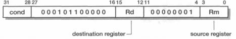
Binary encoding
Figure 5.8 Count leading zeros instruction binary encoding.
Single word and unsigned byte data transfer instructions |
125 |
Description |
The instruction sets Rd to the number of the bit position of the most significant 1 in |
|
Rm. If Rm is zero Rd will be set to 32. |
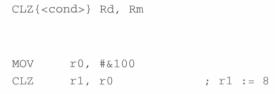
Assembler |
|
format |
|
Example |
|
Notes
1.Only processors that implement ARM architecture v5T support the CLZ instruction (see Section 5.23 on page 147).
5.10Single word and unsigned byte data transfer instructions
|
These instructions are the most flexible way to transfer single bytes or words of data |
|
between ARM's registers and memory. Transferring large blocks of data is usually |
|
better done using the multiple register transfer instructions, and recent ARM proces- |
|
sors also support instructions for transferring half-words and signed bytes. |
|
Provided that a register has been initialized to point somewhere near (usually |
|
within 4 Kbytes of) the required memory address, these instructions provide an effi- |
|
cient load and store mechanism with a relatively rich set of addressing modes which |
|
includes immediate and register offsets, auto-indexing and PC-relative. |
Description |
These instructions construct an address starting from a base register (Rn), then |
|
adding (U = 1) or subtracting (U = 0) an unsigned immediate or (possibly scaled) |
|
register offset. The base or computed address is used to load (L = 1) or store (L = 0) |
|
an unsigned byte (B = 1) or word (B = 0) quantity to or from a register (Rd), from or |
|
to memory. When a byte is loaded into a register it is zero extended to 32 bits. When |
|
a byte is stored into memory, the bottom eight bits of the register are stored into the |
|
addressed location. |
|
A pre-indexed (P = 1) addressing mode uses the computed address for the load or |
|
store operation, and then, when write-back is requested (W =1), updates the base reg- |
|
ister to the computed value. |

126 |
The ARM Instruction Set |
Binary encoding
Figure 5.9 Single word and unsigned byte data transfer instruction binary encoding.
A post-indexed (P = 0) addressing mode uses the unmodified base register for the transfer and then updates the base register to the computed address irrespective of the W bit (since the offset has no significance other than as a base register modifier, and can always be set to immediate zero if no change is desired). Since the W bit is unused in this case, it has an alternative function which is only relevant in code which is not running in user mode: setting W = 1 causes the processor to request a user mode access to memory, allowing the operating system to adopt a user view of the memory translation and protection scheme.
Single word and unsigned byte data transfer instructions |
127 |
Assembler |
The pre-indexed form of the instruction: |
format |
LDRlSTR{<cond>}{B} Rd, [Rn, <offset>]{!} The |
|
|
|
post-indexed form: |
|
LDRlSTR{<cond>}{B}{T} Rd, [Rn], <offset> A |
|
useful PC-relative form that leaves the assembler to do all the work: |
LDRlSTR{<COnd>}{B} Rd, LABEL
LDR is 'load register', STR is 'store register'; the optional 'B' selects an unsigned byte transfer, the default is word; <of f set> may be # + /-<l2-bit immediate> or + /-Rm {, shift} where the shift specifier is the same as for data processing instructions except that register specified shift amounts are not available; ! selects write-back (auto-indexing) in the pre-indexed form.
The T flag selects the user view of the memory translation and protection system and should only be used in non-user modes. The user should fully understand the memory management environment in which the processor is being used, so this is really only a facility for operating system experts.
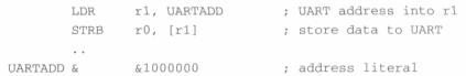
Examples |
To store a byte in r0 to a peripheral: |
The assembler will use a pre-indexed, PC-relative addressing mode to load the address into rl. The literal must be within range (that is, within 4 Kbytes of the load
|
instruction) for this to be possible. |
|
Notes |
1. |
Using the PC as the base address delivers the address of the instruction plus eight |
|
|
bytes; it should not be used as the offset register, nor with any auto-indexing |
|
|
addressing mode (including any post-indexed mode). |
|
2. |
Loading a word into the PC causes a branch to the loaded address and is a recognized |
|
|
way of implementing jump tables. Loading a byte into the PC should be avoided. |
|
3. |
Storing the PC to memory gives different results on different implementations of |
|
|
the processor and should therefore be avoided if possible. |
|
4. |
In general Rd, Rn and Rm should be distinct registers, though loading into the |
|
|
base register (Rd = Rn) is acceptable provided auto-indexing is not used in the |
|
|
same instruction. |
|
5. |
When a word is loaded from a non-word-aligned address the loaded data is the |
|
|
word-aligned word containing the addressed byte, rotated so that the addressed |
|
|
byte is in the least significant byte of the destination register. Some ARM systems |
128 |
The ARM Instruction Set |
may raise an exception under these circumstances (controlled by the A flag in bit 1 of CP15 register 1, described in Section 11.2 on page 293).
6.When a word is stored to a non-word-aligned address the bottom two bits of the address are ignored and the word is stored as though they had been zero. Some ARM systems may raise an exception under these circumstances (again controlled by the A flag in CP15 register 1).
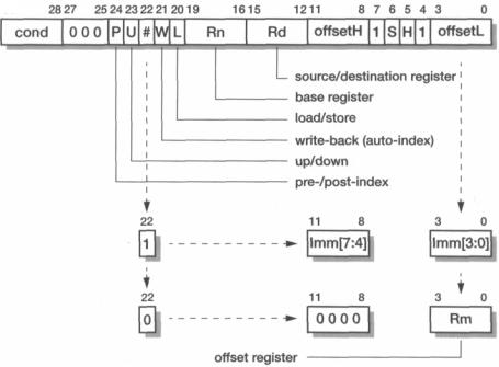
5.11Half-word and signed byte data transfer instructions
These instructions are not supported by some early ARM processors. As a result of their late addition to the architecture they are somewhat 'shoe-horned' into the instruction space as indicated by the split immediate field.
The addressing modes available with these instructions are a subset of those available with the unsigned byte and word forms.
Binary encoding
31
Figure 5.10 Half-word and signed byte data transfer instruction binary encoding.

Half-word and signed byte data transfer instructions |
129 |
Description
Assembler formats
These instructions are very similar to the word and unsigned byte forms described in the previous section, but here the immediate offset is limited to eight bits and the scaled register offset is no longer available.
Table 5.6 Data type encoding.
The S and H bits define the type of the operand to be transferred as listed in Table 5.6. Note that the fourth combination of these bits, corresponding to an unsigned byte type, is not available in this format. The format described in the previous section should be used instead. Since there is no difference between storing signed and unsigned data, the only relevant forms of this instruction format are:
•Load signed byte, signed half-word or unsigned half-word.
•Store half-word.
An unsigned value is zero-extended to 32 bits when loaded; a signed value is extended to 32 bits by replicating the most significant bit of the data.
The pre-indexed form:
LDR|STR{<cond>}H|SHI SB Rd, [Rn, <offset>] { ! }
The post-indexed form:
LDRlSTR{<cond>}H|SHlSB Rd, [Rn], <offset>
where <of fset> is # + /-<8-bit immediate> or +/-Rm and HI SHI SB selects the data type; otherwise the assembler format is as for words and unsigned byte transfers.