

ethwm30d
.pdfQuick Start
Board Installation
1 Remove the board from the antistatic bag. Visually inspect the board to verify that it was not damaged during shipment. Do not use the antistatic bag as a underlying pad for Ethernut, because it’s electroconductive. Put the board on a wooden surface or simply on a piece of paper. Plastic surfaces may be harmful because of electrostatic discharge.
WARNING: As with all computer equipment, the Ethernut board may be severely damaged by electrostatic discharge (ESD). Be sure to take proper precautions before removing the Ethernut board from the antistatic bag. Never pass the board from one person’s hand to another.
2Connect Ethernut`s DB-9 RS232 port to an available COM port using the serial cable.
3Use one twisted pair cable to connect Ethernut's RJ-45 connector to the hub or switch and the other twisted pair cable to connect the hub or switch with the network adapter in the PC. If you are not using a hub or switch, then directly connect the Ethernut board with the PC’s network adapter using a twisted pair cross cable.
4Connect the power supply to the barrel connector on the Ethernut board. The Ethernut board is equipped with its own rectifier bridge and voltage regulator. Therefore the polarity of the barrel connector isn't important.
WARNING: The power supply should not be plugged into an electrical outlet before connecting it to the Ethernut board.
5Apply power to the Ethernut board by connecting the power supply to an electrical outlet. When the board is powered up, the red power LED should go on.
6Start the terminal emulation program at 115200 baud, no parity, 8 data bits, and 1 stop bit. Disable hardware (RTS/CTS) and software (XON/XOFF) flow control.
Baudrate
The baudrate of the Ethernut board is specified by the CPU clock (IC5, 73.720 MHz by default) and a baudrate divisor ranging from 0 to 65535.
The actual baudrate can be calculated by
baudrate = CPU clock / (16 * divisor)
7
Ethernut Hardware Manual
7 Reset the Ethernut board by depressing and releasing the reset switch located near the MMC socket. Hold down the spacebar on the terminal emulation program and wait until the BootMon welcome message is displayed.
See the next chapter for a detailed description of the BootMon program.
8

Bootloader
Using the Bootloader
Using the preloaded BootMon firmware to load Ethernut applications.
When using a terminal emulation program like described in the previous chapter, hold down the space bar on the PC keyboard and press and release the reset button on the Ethernut board. This is the tiny push button with the red LED at the board’s edge near the MMC socket. After some seconds the following output should appear in the terminal emulation window:
BootMon 1.0.1
MAC address (000698300000):
Your preloaded version may be higher and the MAC address will differ.
The bootloader is resident, which means, that it is started each time you apply power to the board or press the reset button. However, it will normally work silently in the background, using any previously entered configuration. To change this configuration, a space character must be send to the serial port immediately after starting. Let’s enter a new configuration now.
The MAC address should have been correctly set. Press enter to confirm this parameter.
A MAC address, also referred to as the hardware or Ethernet address is a unique 48 bit number assigned to every Ethernet node. The upper 24 bits are the manufacturer's ID, assigned by the IEEE Standards Office. The ID of Ethernut boards manufactured by egnite Software GmbH is 000698 hexadecimal. The lower 24 bits are the board's unique ID assigned by the manufacturer of the board. Boards produced by egnite do have a unique ID, which is written on the board.
BootMon will ask for the IP Address of the board. |
|
IP address (0.0.0.0): |
|
If your network provides a DHCP service, you can leave the IP address at all |
|
zeros. However, for a first test it is recommended to specify an individual |
|
address, which fits to your local network. For example, let’s assume, that your PC |
|
got IP address 192.168.0.3, than 192.168.0.4 should work, provided that no other |
|
device in your network is using this address. |
|
Enter the individual IP address and press enter. BootMon will prompt for the |
|
network mask. |
|
Net mask (255.255.255.0): |
|
You must use the same network mask as it is used with your PC. In general, all |
|
nodes within a local IP network must have the same network mask. |
|
After entering a network mask, BootMon asks for a default route. |
|
Default route (0.0.0.0): |
|
This should be the IP address of your router, used to connect to the Internet. This |
|
information is only required, if the Ethernut board will be accessed from or will |
9 |
|
Ethernut Hardware Manual
access another node via the Internet. For now we can leave this entry at 0.0.0.0, which means, that no Internet gateway should be used.
Finally BootMon will ask for the TFTP Server IP and for the name of the image to load from this server.
TFTP IP (192.168.192.2):
TFTP Image (threads.bin):
The IP address should be the one of your PC. The name of the image is actually the Ethernut Application we will load into the board.
After pressing enter to confirm the TFTP image name, all parameters will be stored in non-volatile EEPROM memory and BootMon will immediately try to load the specified file from the specified TFTP server.
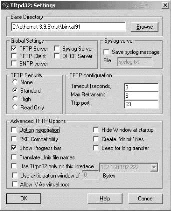
TFTP Server
There are a number of TFTP servers available, many of them are free of charge.
For Windows, TFTPD32 is a good choice. With Linux, a TFTP daemon is typically installed already, it just needs to be activated.
The following screenshot shows a sample configuration of TFTPD32. The Base Directory point to the directory that contains the precompiled Nut/OS application binaries.
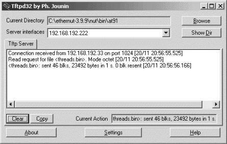
After pressing the reset button, BootMon will request the binary image from the TFTP server running on your PC. On TFTPD32 the following should appear.
10
Bootloader
The sample contained in threads.bin demonstrates NUT/OS multithreading capabilities and outputs a series of Hs, Ms and Ls. You may want to check the source code of this sample now or try some of the other samples.
11
Ethernut Hardware Manual
Jumper Configuration
Adapting Ethernut to specific requirements.
Jumper Overview
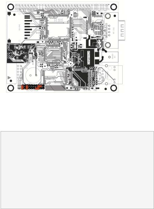
Almost any available configuration is done in the CPLD except setting up the JTAG chain. For this, JP5 is used. The picture below shows the default configuration, where the JTAG connector is directly attached to the CPU.
JTAG Port
The angled, boxed 10-pin header connector allows serial programming of the AT91R40008 as well as the CPLD without physical removal of the chips from the system.
WARNING: Unlike previous board revisions, Ethernut 3.0 doesn`t support programming with ISP Adapters. Thus, you can`t use one of the programming adapters from previous Ethernut boards. Make sure to either use the programming adapter of the Ethernut 3.0 Starter Kit, Atmel`s ATJTAGICE or any other compatible JTAG adapter. Connecting an ISP adapter to the Ethernut 3.0 JTAG connector will at least blow the board`s fuse or in worst cases destroy your Ethernut. Also note, that the adapter from the Ethernut 3.0 Starter Kit provides both, ISP and JTAG programming, using two clearly marked cables. Never plug the ISP cable into the Ethernut 3.0 programming connector. Always use the cable, which is clearly marked with the label “JTAG”.
12
Network Configuration
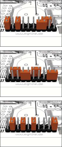
JP5 Jumper JP5 routes the JTAG signals to the AT91R40008, if pins 1 and 2 and pins 5 and 6 are shortened.
JP5 Routing the JTAG interface to the CPLD is provided by shortening pins 1 and 3, 4 and 6, 7 and 8 as well as pins 9 and 10. However, you need a special Xilinx adapter for programming the CPLD via JTAG.
JP5 As an alternative, the Ethernut is able to program its own CPLD. The required jumper configuration is shown on the left.
13
Ethernut Hardware Manual
Hardware Expansion
Ethernut and custom hardware.
Many applications will do just fine with nothing else than the Ethernut or external hardware may be connected to the RS-232 port. However, if more is required, the Ethernut expansion port is the first choice to add custom designed hardware.
Expansion Port
Add-on boards can be added to the expansion port. This connector contains partial CPU data and address bus, memory read/write signals, digital I/O ports, reset signal and power supply. Nearly all microcontroller pins are available at the expansion port connector, providing an interface with several features like 2-wire interface (I2C) or counter inputs and outputs. It is strictly recommended to consult the AT19R40008 data sheet before attaching hardware to the expansion port.
Many signals are routed through the CPLD and may be redefined by reprogramming this chip.
Although available at the connector, some signals are used internally by Ethernut and can’t be used by external hardware. Carefully check the schematic.
The following table lists the expansion port’s pin assignment.
14
Hardware Expansion
Pin |
Signal |
Description |
|
|
Pin |
Signal |
Description |
|
|
||||||
1 |
VCC3 |
Regulated |
+3.3V |
|
2 |
VCC3 |
Regulated |
+3.3V |
|
||||||
|
|
|
|
|
|
|
|
||||||||
3 |
NC |
Not connected |
|
4 |
NC |
Not connected |
|
||||||||
|
|
|
|
|
|
|
|
|
|
||||||
5 |
GND |
Signal |
ground |
|
6 |
GND |
Signal |
ground |
|
||||||
|
|
|
|
|
|
|
|
|
|
||||||
7 |
GND |
Signal |
ground |
|
8 |
GND |
Signal |
ground |
|
||||||
9 |
MR\ |
Reset |
input |
|
|
10 |
DC |
Unregulated supply |
|||||||
|
|
|
|
|
|
|
|
||||||||
11 |
NC |
Not connected |
|
12 |
NC |
Not connected |
|
||||||||
|
|
|
|
|
|
|
|
|
|
|
|||||
13 |
RD\ |
Memory |
read |
signal |
|
14 |
WR\ |
Memory |
write |
signal |
|||||
|
|
|
|
|
|
|
|
|
|
|
|
|
|||
15 |
D0 |
Data |
bus |
bit 0 |
|
16 |
D1 |
Data |
bus |
bit |
1 |
|
|||
|
|
|
|
|
|
|
|
|
|
|
|
|
|||
17 |
D2 |
Data |
bus |
bit 2 |
|
18 |
D3 |
Data |
bus |
bit |
3 |
|
|||
|
|
|
|
|
|
|
|
|
|
|
|
|
|||
19 |
D4 |
Data |
bus |
bit 4 |
|
20 |
D5 |
Data |
bus |
bit |
5 |
|
|||
|
|
|
|
|
|
|
|
|
|
|
|
|
|||
21 |
D6 |
Data |
bus |
bit 6 |
|
22 |
D7 |
Data |
bus |
bit |
7 |
|
|||
|
|
|
|
|
|
|
|
|
|
|
|
||||
23 |
A0 |
Address |
bus |
bit 0 |
|
24 |
A1 |
Address |
bus |
bit |
1 |
||||
25 |
A2 |
Address |
bus |
bit 2 |
|
26 |
A3 |
Address |
bus |
bit |
3 |
||||
|
|
|
|
|
|
|
|
|
|
|
|
||||
27 |
A4 |
Address |
bus |
bit 4 |
|
28 |
A5 |
Address |
bus |
bit |
5 |
||||
|
|
|
|
|
|
|
|
|
|
|
|
||||
29 |
A6 |
Address |
bus |
bit 6 |
|
30 |
A7 |
Address |
bus |
bit |
7 |
||||
|
|
|
|
|
|
|
|
|
|
|
|
||||
31 |
A8 |
Address |
bus |
bit 8 |
|
32 |
A9 |
Address |
bus |
bit |
9 |
||||
|
|
|
|
|
|
|
|
|
|
|
|
||||
33 |
A10 |
Address |
bus |
bit 10 |
|
34 |
A11 |
Address |
bus |
bit |
11 |
||||
|
|
|
|
|
|
|
|
|
|
|
|
||||
35 |
A12 |
Address |
bus |
bit 12 |
|
36 |
A13 |
Address |
bus |
bit |
13 |
||||
|
|
|
|
|
|
|
|
|
|
|
|
||||
37 |
A14 |
Address |
bus |
bit 14 |
|
38 |
A15 |
Address |
bus |
bit |
15 |
||||
|
|
|
|
|
|
|
|
|
|
|
|||||
39 |
P15 |
UART |
0 |
Receive |
|
40 |
P14 |
UART |
0 |
Transceive |
|||||
41 |
P13 |
UART |
0 |
Clock |
|
|
42 |
P8 |
Timer |
2 |
I/O |
B |
|
||
|
|
|
|
|
|
|
|
|
|
|
|||||
43 |
P9 |
External |
IRQ0 |
|
44 |
P27 |
Chip |
select |
3 |
|
|||||
|
|
|
|
|
|
|
|
|
|
|
|
||||
45 |
P11 |
External |
IRQ2 |
|
46 |
P12 |
Fast |
IRQ |
|
|
|
||||
|
|
|
|
|
|
|
|
|
|
|
|
|
|||
47 |
P0 |
Timer |
0 |
Clock |
|
48 |
P1 |
Timer |
0 |
I/O |
A |
|
|||
|
|
|
|
|
|
|
|
|
|
|
|
||||
49 |
P2 |
Timer |
0 |
I/O B |
|
50 |
P3 |
Timer |
1 |
Clock |
|
||||
|
|
|
|
|
|
|
|
|
|
|
|
|
|||
51 |
P4 |
Timer |
1 |
I/O A |
|
52 |
P5 |
Timer |
1 |
I/O |
B |
|
|||
|
|
|
|
|
|
|
|
|
|
|
|
|
|||
53 |
P6 |
Timer |
2 |
Clock |
|
54 |
P7 |
Timer |
2 |
I/O |
A |
|
|||
55 |
P17 |
GPIO |
|
|
|
|
|
56 |
P16 |
GPIO |
|
|
|
|
|
57 |
P22 |
UART |
1 |
Receive |
|
58 |
P21 |
UART |
1 |
Transmit |
|
||||
|
|
|
|
|
|
|
|
|
|
|
|
|
|
|
|
59 |
P23 |
GPIO |
|
|
|
|
|
60 |
P20 |
UART |
1 |
Clock |
|
|
|
|
|
|
|
|
|
|
|
|
|
|
|
|
|
|
|
61 |
P19 |
GPIO |
|
|
|
|
|
62 |
P18 |
GPIO |
|
|
|
|
|
|
|
|
|
|
|
|
|
||||||||
63 |
NC |
Not connected |
|
64 |
NC |
Not connected |
|
||||||||
|
|
|
|
|
|
|
|
|
|
|
|
|
|
|
|
15
Ethernut Hardware Manual
Troubleshooting
Problem |
Solution |
BootMon produces garbage |
BootMon was unable to detect a |
output and the yellow LED |
space characters at the required |
at the RJ45 goes on after |
baudrate. The terminal emulator may |
a few seconds. |
use a wrong baudrate not send any |
|
characters because of handshake |
|
settings or other RS-232 |
|
communication issues. |
|
|
The red LED does not go |
The fuse may be blown. Remove any |
on when applying power. |
kind of attached hardware and |
|
remove all jumpers. Make sure the |
|
board is placed on a non conductive |
|
surface like a piece of paper. |
|
Replace the fuse (0.6A superfast) |
|
and supply the board via the barrel |
|
connector J2 only with not more |
|
than 24V DC. Best use a lab power |
|
supply with current control and |
|
carefully increase the voltage |
|
starting from 3V. The board should |
|
not draw more than 150 milliamps. |
|
|
The green LED at the RJ45 |
The green LED will go on only if |
connector does not go on |
Ethernut is connected to an |
after pressing the reset |
Ethernet network and the Ethernut |
button. |
software properly initialized the |
|
LAN controller hardware on the |
|
Ethernut. Load the board with |
|
BootMon image via JTAG. Replace the |
|
Ethernet cable and try the same |
|
connection with your PC to make |
|
sure that the network link is |
|
working. |
|
|
16