

ethwm10
.pdf5 Functional Description
Watchdog Timer
Software bugs, temporary hardware failures caused by electrical transients or interference and many other problems might cause the system to malfunction. The ATmega128 microcontroller (IC1) provides an on-chip watchdog timer, which forces a system reset, if the application program fails to periodically update this timer.
System Clock
The ATmega 128 microcontroller clock is generated by a 14.7456 MHz crystal (Q1), which may be replaced by a crystal of up to 16 MHz. An additional 32.768 kHz crystal (Q2) drives an on-chip asynchronous timer, which is typically used for a software realtime clock. The Ethernet controller is driven by a seperate 20-MHz crystal (Q3).
WARNING: Note, that changing any crystal will alter the Ethernut board's EMC characteristics and require re-testing.
Flash ROM
The ATmega 128 provides 128 kBytes of on-chip, non-volatile flash memory space, which is used for program code and read-only data storage. This memory is organized as 64K x 16 bits and can be (re-)programmed through in-system programming.
Static RAM
The Ethernut board provides 512 kByte SRAM (IC4), which is used as read/write data storage. The lower 4 kBytes are overlayed by the ATmega128 internal register and SRAM space. The required address latch is provided by the CPLD (IC3).
With it's 16 bit address bus the ATmega128 can address upto 64 kByte RAM only. The lower 32 kByte on the Ethernut board are fixed.
EEPROM
The ATmega 128 provides 4 kBytes of on-chip, non-volatile, electrically erasable memory, typically used for configuration data storage. This memory provides read/write access under program control as well as through insystem programming. Note, that EEPROM write access is much slower (about 2.5 ms) than writing to SRAM.
17
Ethernut Hardware Manual
6 Troubleshooting
This chapter will help you in case of problems.
Problem Solution
Problem
The red power LED is not on.
Nothing happens when pushing the RESET button.
The terminal emulation on the PC does not show the BaseMon software prompt.
The terminal emulation software displays unreadable characters
The AVR device cannot be programmed.
Fix
Connect the DC power cable. Check that the power supply is of DC type 8-12V min. 500 mA. Check the fuse.
Sometimes it is difficult to make a good connection when pushing the small button. Try pushing it in the center.
Check the COM port connection with the Ethernut board. Make sure that the same COM port is selected in the terminal emulation software. Verify the check the cables, etc. Try using a different baudrate and make sure, that the terminal emulation repeatingly transmits space characters while the spacebar is held down. If not sure, try another program. Make sure, that any flow control is switched off and jumper JP1 is properly set.
Check the word length, number of stop bits and parity setting of the terminal emulation software. It should be set to 8 data bits, no parity and 1 stop bit.
You need to completely erase the device before programming.
18
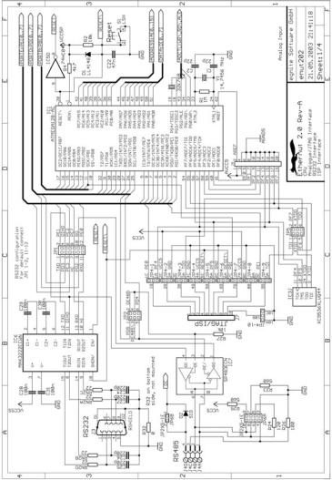
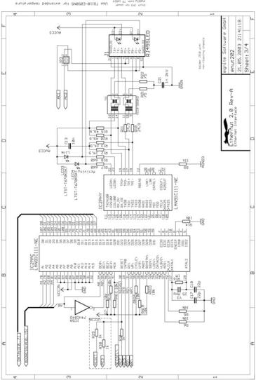
7 Schematics
7 Schematics
19

Ethernut Hardware Manual
20
7 Schematics
21

Ethernut Hardware Manual
22
8 Index
Index
A About the Ethernut 2 Board |
1 |
B Quick Start |
3 |
C Testing the Board |
5 |
D Network Configuration |
7 |
E Functional Description |
9 |
F Troubleshooting |
18 |
G Schematics |
19 |
23

egnite Software GmbH |
Fon |
+49 (0)23 23-92 53 75 |
Westring 303 |
Fax |
+49 (0)23 23-92 53 74 |
44629 Herne |
info@egnite.de |
|
Germany |
|
|
http://www.egnite.de
http://www.ethernut.de