

Eilam E.Reversing.Secrets of reverse engineering.2005
.pdfLow-Level Software 41
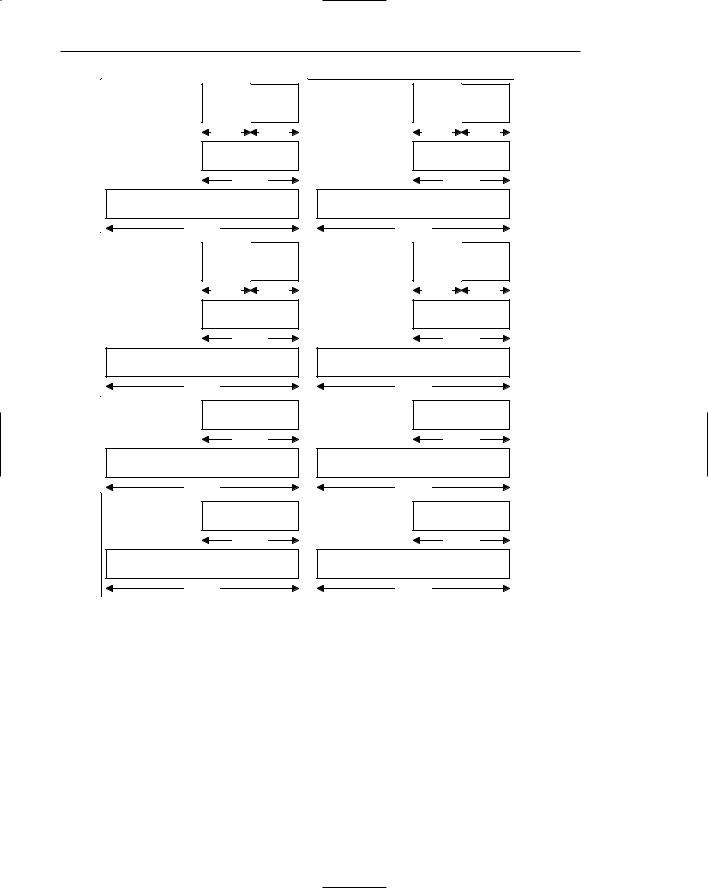
Code Executed:
PUSH Value 1
PUSH Value 2
PUSH Value 3
After PUSH
32 Bits
Unknown Data (Unused) |
Lower Memory |
|
Addresses |
||
|
||
Unknown Data (Unused) |
Direction |
|
Value 3 |
||
|
||
Value 2 |
PUSH |
|
Value 1 |
||
ESP |
Higher Memory |
|
Previously Stored Value |
||
Addresses |
||
|
Figure 2.1 A view of the stack after three values are pushed in.
Code Executed:
POP EAX
POP EBX
POP ECX
After POP
|
|
|
|
|
32 Bits |
|
|
|
|
|
Unknown Data (Unused) |
||
|
|
|
|
|||
|
|
|
|
Unknown Data (Unused) |
||
|
|
|
|
Unknown Data (Unused) |
||
|
|
|
|
Unknown Data (Unused) |
||
|
|
Unknown Data (Unused) |
||||
ESP |
|
|
||||
|
|
|
|
Previously Stored Value |
||
|
|
|
|
|||
|
|
|
|
|||
|
|
|
|
|
|
|
Lower Memory
Addresses
Direction
POP
Higher Memory
Addresses
Figure 2.2 A view of the stack after the three values are popped out.

42 Chapter 2
If you try to translate stack usage to a high-level perspective, you will see that the stack can be used for a number of different things:
■■Temporarily saved register values: The stack is frequently used for temporarily saving the value of a register and then restoring the saved value to that register. This can be used in a variety of situations—when a procedure has been called that needs to make use of certain registers. In such cases, the procedure might need to preserve the values of registers to ensure that it doesn’t corrupt any registers used by its callers.
■■Local variables: It is a common practice to use the stack for storing local variables that don’t fit into the processor’s registers, or for variables that must be stored in RAM (there is a variety of reasons why that is needed, such as when we want to call a function and have it write a value into a local variable defined in the current function). It should be noted that when dealing with local variables data is not pushed and popped onto the stack, but instead the stack is accessed using offsets, like a data structure. Again, this will all be demonstrated once you enter the real reversing sessions, in the second part of this book.
■■Function parameters and return addresses: The stack is used for implementing function calls. In a function call, the caller almost always passes parameters to the callee and is responsible for storing the current instruction pointer so that execution can proceed from its current position once the callee completes. The stack is used for storing both parameters and the instruction pointer for each procedure call.
Heaps
A heap is a managed memory region that allows for the dynamic allocation of variable-sized blocks of memory in runtime. A program simply requests a block of a certain size and receives a pointer to the newly allocated block (assuming that enough memory is available). Heaps are managed either by software libraries that are shipped alongside programs or by the operating system.
Heaps are typically used for variable-sized objects that are used by the program or for objects that are too big to be placed on the stack. For reversers, locating heaps in memory and properly identifying heap allocation and freeing routines can be helpful, because it contributes to the overall understanding of the program’s data layout. For instance, if you see a call to what you know is a heap allocation routine, you can follow the flow of the procedure’s return value throughout the program and see what is done with the allocated block, and so on. Also, having accurate size information on heap-allocated objects (block size is always passed as a parameter to the heap allocation routine) is another small hint towards program comprehension.

Low-Level Software 43
Executable Data Sections
Another area in program memory that is frequently used for storing application data is the executable data section. In high-level languages, this area typically contains either global variables or preinitialized data. Preinitialized data is any kind of constant, hard-coded information included with the program. Some preinitialized data is embedded right into the code (such as constant integer values, and so on), but when there is too much data, the compiler stores it inside a special area in the program executable and generates code that references it by address. An excellent example of preinitialized data is any kind of hard-coded string inside a program. The following is an example of this kind of string.
char szWelcome = “This string will be stored in the executable’s
preinitialized data section”;
This definition, written in C, will cause the compiler to store the string in the executable’s preinitialized data section, regardless of where in the code szWelcome is declared. Even if szWelcome is a local variable declared inside a function, the string will still be stored in the preinitialized data section. To access this string, the compiler will emit a hard-coded address that points to the string. This is easily identified while reversing a program, because hard-coded memory addresses are rarely used for anything other than pointing to the executable’s data section.
The other common case in which data is stored inside an executable’s data section is when the program defines a global variable. Global variables provide long-term storage (their value is retained throughout the life of the program) that is accessible from anywhere in the program, hence the term global. In most languages, a global variable is defined by simply declaring it outside of the scope of any function. As with preinitialized data, the compiler must use hardcoded memory addresses in order to access global variables, which is why they are easily recognized when reversing a program.
Control Flow
Control flow is one of those areas where the source-code representation really makes the code look user-friendly. Of course, most processors and low-level languages just don’t know the meaning of the words if or while. Looking at the low-level implementation of a simple control flow statement is often confusing, because the control flow constructs used in the low-level realm are quite primitive. The challenge is in converting these primitive constructs back into user-friendly high-level concepts.

44 Chapter 2
One of the problems is that most high-level conditional statements are just too lengthy for low-level languages such as assembly language, so they are broken down into sequences of operations. The key to understanding these sequences, the correlation between them, and the high-level statements from which they originated, is to understand the low-level control flow constructs and how they can be used for representing high-level control flow statements. The details of these low-level constructs are platformand language-specific; we will be discussing control flow statements in IA-32 assembly language in the following section on assembly language.
Assembly Language 101
In order to understand low-level software, one must understand assembly language. For most purposes, assembly language is the language of reversing, and mastering it is an essential step in becoming a real reverser, because with most programs assembly language is the only available link to the original source code. Unfortunately, there is quite a distance between the source code of most programs and the compiler-generated assembly language code we must work with while reverse engineering. But fear not, this book contains a variety of techniques for squeezing every possible bit of information from assembly language programs!
The following sections provide a quick introduction to the world of assembly language, while focusing on the IA-32 (Intel’s 32-bit architecture), which is the basis for all of Intel’s x86 CPUs from the historical 80386 to the modern-day implementations. I’ve chosen to focus on the Intel IA-32 assembly language because it is used in every PC in the world and is by far the most popular processor architecture out there. Intel-compatible CPUs, such as those made by Advanced Micro Devices (AMD), Transmeta, and so on are mostly identical for reversing purposes because they are object-code-compatible with Intel’s processors.
Registers
Before starting to look at even the most basic assembly language code, you must become familiar with IA-32 registers, because you’ll be seeing them referenced in almost every assembly language instruction you’ll ever encounter. For most purposes, the IA-32 has eight generic registers: EAX, EBX, ECX, EDX,

Low-Level Software 45
ESI, EDI, EBP, and ESP. Beyond those, the architecture also supports a stack of floating-point registers, and a variety of other registers that serve specific system-level requirements, but those are rarely used by applications and won’t be discussed here. Conventional program code only uses the eight generic registers.
Table 2.1 provides brief descriptions of these registers and their most common uses.
Notice that all of these names start with the letter E, which stands for extended. These register names have been carried over from the older 16-bit Intel architecture, where they had the exact same names, minus the Es (so that EAX was called AX, etc.). This is important because sometimes you’ll run into 32-bit code that references registers in that way: MOV AX, 0x1000, and so on. Figure 2.3. shows all general purpose registers and their various names.
Table 2.1 Generic IA-32 Registers and Their Descriptions
EAX, EBX, EDX |
These are all generic registers that can be used for any |
|
integer, Boolean, logical, or memory operation. |
|
|
ECX |
Generic, sometimes used as a counter by repetitive |
|
instructions that require counting. |
ESI/EDI |
Generic, frequently used as source/destination pointers |
|
in instructions that copy memory (SI stands for Source |
|
Index, and DI stands for Destination Index). |
|
|
EBP |
Can be used as a generic register, but is mostly used as |
|
the stack base pointer. Using a base pointer in |
|
combination with the stack pointer creates a stack |
|
frame. A stack frame can be defined as the current |
|
function’s stack zone, which resides between the stack |
|
pointer (ESP) and the base pointer (EBP). The base |
|
pointer usually points to the stack position right after the |
|
return address for the current function. Stack frames are |
|
used for gaining quick and convenient access to both |
|
local variables and to the parameters passed to the |
|
current function. |
ESP |
This is the CPUs stack pointer. The stack pointer stores |
|
the current position in the stack, so that anything pushed |
|
to the stack gets pushed below this address, and this |
|
register is updated accordingly. |
46 |
Chapter 2 |
|
|
|
|
|
|
|
|
|
AH |
|
AL |
|
BH |
|
BL |
|
8 |
Bits |
8 |
Bits |
8 |
Bits |
8 |
Bits |
|
|
|
AX |
|
|
|
BX |
|
|
|
16 Bits |
|
|
16 Bits |
|
||
|
EAX |
|
|
|
EBX |
|
|
|
|
32 Bits |
|
|
|
32 Bits |
|
|
|
|
|
CH |
|
CL |
|
DH |
|
DL |
|
8 |
Bits |
8 |
Bits |
8 |
Bits |
8 |
Bits |
|
|
|
CX |
|
|
|
DX |
|
|
|
16 Bits |
|
|
16 Bits |
|
||
|
ECX |
|
|
|
EDX |
|
|
|
|
32 Bits |
|
|
|
32 Bits |
|
|
|
|
|
|
SP |
|
|
|
BP |
|
|
|
16 Bits |
|
|
16 Bits |
|
||
|
ESP |
|
|
|
EBP |
|
|
|
|
32 Bits |
|
|
|
32 Bits |
|
|
|
|
|
|
SI |
|
|
|
DI |
|
|
|
16 Bits |
|
|
16 Bits |
|
||
|
ESI |
|
|
|
EDI |
|
|
|
|
32 Bits |
|
|
|
32 Bits |
|
|
|
Figure 2.3 General-purpose registers in IA-32.
Flags
IA-32 processors have a special register called EFLAGS that contains all kinds of status and system flags. The system flags are used for managing the various processor modes and states, and are irrelevant for this discussion. The status flags, on the other hand, are used by the processor for recording its current logical state, and are updated by many logical and integer instructions in order to record the outcome of their actions. Additionally, there are instructions that operate based on the values of these status flags, so that it becomes possible to

Low-Level Software 47
create sequences of instructions that perform different operations based on different input values, and so on.
In IA-32 code, flags are a basic tool for creating conditional code. There are arithmetic instructions that test operands for certain conditions and set processor flags based on their values. Then there are instructions that read these flags and perform different operations depending on the values loaded into the flags. One popular group of instructions that act based on flag values is the Jcc (Conditional Jump) instructions, which test for certain flag values (depending on the specific instruction invoked) and jump to a specified code address if the flags are set according to the specific conditional code specified.
Let’s look at an example to see how it is possible to create a conditional statement like the ones we’re used to seeing in high-level languages using flags. Say you have a variable that was called bSuccess in the high-level language, and that you have code that tests whether it is false. The code might look like this:
if (bSuccess == FALSE) return 0;
What would this line look like in assembly language? It is not generally possible to test a variable’s value and act on that value in a single instruction— most instructions are too primitive for that. Instead, we must test the value of bSuccess (which will probably be loaded into a register first), set some flags that record whether it is zero or not, and invoke a conditional branch instruction that will test the necessary flags and branch if they indicate that the operand handled in the most recent instruction was zero (this is indicated by the Zero Flag, ZF). Otherwise the processor will just proceed to execute the instruction that follows the branch instruction. Alternatively, the compiler might reverse the condition and branch if bSuccess is nonzero. There are many factors that determine whether compilers reverse conditions or not. This topic is discussed in depth in Appendix A.
Instruction Format
Before we start discussing individual assembly language instructions, I’d like to introduce the basic layout of IA-32 instructions. Instructions usually consist of an opcode (operation code), and one or two operands. The opcode is an instruction name such as MOV, and the operands are the “parameters” that the instruction receives (some instructions have no operands). Naturally, each instruction requires different operands because they each perform a different task. Operands represent data that is handled by the specific instruction (just like parameters passed to a function), and in assembly language, data comes in three basic forms:

48Chapter 2
■■Register name: The name of a general-purpose register to be read from or written to. In IA-32, this would be something like EAX, EBX, and so on.
■■Immediate: A constant value embedded right in the code. This often indicates that there was some kind of hard-coded constant in the original program.
■■Memory address: When an operand resides in RAM, its memory address is enclosed in brackets to indicate that it is a memory address. The address can either be a hard-coded immediate that simply tells the processor the exact address to read from or write to or it can be a register whose value will be used as a memory address. It is also possible to combine a register with some arithmetic and a constant, so that the register represents the base address of some object, and the constant represents an offset into that object or an index into an array.
The general instruction format looks like this:
Instruction Name (opcode) |
Destination Operand, Source Operand |
Some instructions only take one operand, whose purpose depends on the specific instruction. Other instructions take no operands and operate on predefined data. Table 2.2 provides a few typical examples of operands and explains their meanings.
Basic Instructions
Now that you’re familiar with the IA-32 registers, we can move on to some basic instructions. These are popular instructions that appear everywhere in a program. Please note that this is nowhere near an exhaustive list of IA-32 instructions. It is merely an overview of the most common ones. For detailed information on each instruction refer to the IA-32 Intel Architecture Software Developer’s Manual, Volume 2A and Volume 2B [Intel2, Intel3]. These are the (freely available) IA-32 instruction set reference manuals from Intel.
Table 2.2 Examples of Typical Instruction Operands and Their Meanings
OPERAND |
DESCRIPTION |
EAX |
Simply references EAX, either for reading or writing |
|
|
0x30004040 |
An immediate number embedded in the code (like a |
|
constant) |
[0x4000349e] |
An immediate hard-coded memory address—this can be a |
|
global variable access |
|
|

Low-Level Software 49
THE AT&T ASSEMBLY LANGUAGE NOTATION
Even though the assembly language instruction format described here follows the notation used in the official IA-32 documentation provided by Intel, it is not the only notation used for presenting IA-32 assembly language code. The AT&T Unix notation is another notation for assembly language instructions that is quite different from the Intel notation. In the AT&T notation the source operand usually precedes the destination operand (the opposite of how it is done in the Intel notation). Also, register names are prefixed with an % (so that EAX is referenced as %eax). Memory addresses are denoted using parentheses, so that %(ebx) means “the address pointed to by EBX.” The AT&T notation is mostly used in Unix development tools such as the GNU tools, while the Intel notation is primarily used in Windows tools, which is why this book uses the Intel notation for assembly language listings.
Moving Data
The MOV instruction is probably the most popular IA-32 instruction. MOV takes two operands: a destination operand and a source operand, and simply moves data from the source to the destination. The destination operand can be either a memory address (either through an immediate or using a register) or a register. The source operand can be an immediate, register, or memory address, but note that only one of the operands can contain a memory address, and never both. This is a generic rule in IA-32 instructions: with a few exceptions, most instructions can only take one memory operand. Here is the “prototype” of the MOV instruction:
MOV |
DestinationOperand, SourceOperand |
Please see the “Examples” section later in this chapter to get a glimpse of how MOV and other instructions are used in real code.
Arithmetic
For basic arithmetic operations, the IA-32 instruction set includes six basic integer arithmetic instructions: ADD, SUB, MUL, DIV, IMUL, and IDIV. The following table provides the common format for each instruction along with a brief description. Note that many of these instructions support other configurations, with different sets of operands. Table 2.3 shows the most common configuration for each instruction.

50Chapter 2
Table 2.3 Typical Configurations of Basic IA-32 Arithmetic Instructions
INSTRUCTION |
DESCRIPTION |
ADD Operand1, Operand2 |
Adds two signed or unsigned integers. The |
|
result is typically stored in Operand1. |
SUB Operand1, Operand2 |
Subtracts the value at Operand2 from the |
|
value at Operand1. The result is typically stored |
|
in Operand1. This instruction works for both |
|
signed and unsigned operands. |
MUL Operand |
Multiplies the unsigned operand by EAX and |
|
stores the result in a 64-bit value in EDX:EAX. |
|
EDX:EAX means that the low (least significant) |
|
32 bits are stored in EAX and the high (most |
|
significant) 32 bits are stored in EDX. This is a |
|
common arrangement in IA-32 instructions. |
|
|
DIV Operand |
Divides the unsigned 64-bit value stored in |
|
EDX:EAX by the unsigned operand. Stores the |
|
quotient in EAX and the remainder in EDX. |
|
|
IMUL Operand |
Multiplies the signed operand by EAX and |
|
stores the result in a 64-bit value in EDX:EAX. |
|
|
IDIV Operand |
Divides the signed 64-bit value stored in |
|
EDX:EAX by the signed operand. Stores the |
|
quotient in EAX and the remainder in EDX. |
|
|
Comparing Operands
Operands are compared using the CMP instruction, which takes two operands:
CMP
Operand1, Operand2
CMP records the result of the comparison in the processor’s flags. In essence, CMP simply subtracts Operand2 from Operand1 and discards the result, while setting all of the relevant flags to correctly reflect the outcome of the subtraction. For example, if the result of the subtraction is zero, the Zero Flag (ZF) is set, which indicates that the two operands are equal. The same flag can be used for determining if the operands are not equal, by testing whether ZF is not set. There are other flags that are set by CMP that can be used for determining which operand is greater, depending on whether the operands are signed or unsigned. For more information on these specific flags refer to Appendix A.