

Dueck R.Digital design with CPLD applications and VHDL.2000
.pdf510 C H A P T E R 1 1 • Logic Gate Circuitry
SECTION 11.3 REVIEW PROBLEM
11.3The input and output currents IOH, IOL, IIH, and IIL of a TTL device may be classified as source currents or sink currents. List each input or output current as a source or sink current.
14.4Power Dissipation
K E Y T E R M S
Power dissipation The electrical energy used by a logic circuit in a specified period of time. Abbreviation: PD
VCC |
TTL or high-speed CMOS supply voltage. |
ICC |
Total TTL or high-speed CMOS supply current. |
ICCH |
TTL supply current with all outputs HIGH. |
ICCL |
TTL supply current with all outputs LOW. |
IT |
When referring to CMOS supply current, the sum of static and dynamic supply |
currents. |
|
CPD |
Internal capacitance of a high-speed CMOS device used to calculate its |
power dissipation.
Electronic logic gates require a certain amount of electrical energy to operate. The measure of the energy used over time is called power dissipation. Each of the different families of logic has a characteristic range of values for the power it consumes.
For TTL and CMOS, the power dissipation is calculated as follows:
TTL: |
PD VCC ICC |
|
High-Speed CMOS: |
PD VCC IT |
(IT quiescent dynamic supply |
|
|
current) |
Figure 11.11 shows the supply voltage and current in a 74XX00 NAND gate.
FIGURE 11.11 |
Vcc |
|||
Power Supply Voltage and |
|
|
|
Icc |
|
|
|
||
Current in a 74XX00 |
|
|
|
|
|
|
|||
NAND gate. |
|
|
|
|
Icc
The main difference between the two families is the calculation of supply current. The supply current in a TTL device is different when its outputs are HIGH than when
they are LOW. Thus, supply current, ICC, and therefore power dissipation, depends on the states of the device outputs. If the outputs are switching, ICC is proportional to output duty cycle.
In a CMOS device, very little power is consumed when the device outputs are static. Much more current is drawn from the supply when the outputs switch from one state to another. Thus, the power dissipation of a device depends on the switching frequency of its outputs.
11.4 • Power Dissipation |
511 |
Power Dissipation in TTL Devices
Two values are given for supply current in a TTL data sheet. ICCL is the current drawn from the power supply when all gate outputs are LOW. ICCH is the current drawn from the supply when all outputs are HIGH. If the gate outputs are not all at the same level, the supply current is the sum of currents given by:
|
nH |
nL |
|
ICC ICCH ICCL |
|
|
n |
n |
|
where |
|
|
n is the total number of gates in the package |
|
|
nH is the number of gates whose output is HIGH |
|
|
nL is the number of gates whose output is LOW |
|
|
The power dissipation of a TTL chip also depends on the duty cycle of the gate out- |
|
|
puts. That is, it depends on the fraction of time that the chip’s outputs are HIGH. |
|
|
If we assume that, on average, the outputs of a chip are switching with a duty cycle of |
|
|
50%, the supply current can be calculated as follows: |
|
|
ICC (ICCH ICCL)/2 |
|
|
If the output duty cycle is other than 50%, the supply current is given by: |
|
|
ICC DC ICCH (1 DC) ICCL |
|
|
where DC duty cycle. |
|
|
|
|
EXAMPLE 11.8 |
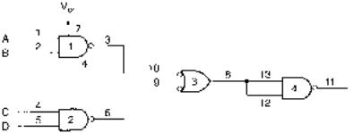
Figure 11.12 shows a circuit constructed from the gates in a 74XX00 quadruple 2-input |
|
|
NAND gate package. Use the data sheet shown in Figure 11.3 to determine the maximum |
|
|
power dissipation of the circuit if the input is DCBA 1001 and the gates are 74LS00 |
|
|
NANDs. Refer to the data sheets in Appendix C and repeat the calculation for 74ALS00 |
|
|
and 74AS00 gates. |
|
FIGURE 11.12
Power Dissipation of 74XX00 NAND
Solution
Gate 1: AB 1
Gate 2: CD 1
Gate 3: AB CD 0
Gate 4: AB CD 1
Since three outputs are HIGH and one is LOW, the supply current is given by:
nH |
nL |
ICC ICCH ICCL |
|
n |
n |
3 ICCH 1 ICCL |
|
4 |
4 |
512 C H A P T E R 1 1 • Logic Gate Circuitry
Maximum supply current for each device is:
74LS00: ICC 0.75(1.6 mA) 0.25(4.4 mA) 2.3 mA 74ALS00: ICC 0.75(0.85 mA) 0.25(3 mA) 1.3875 mA 74AS00: ICC 0.75(3.2 mA) 0.25(17.4 mA) 6.75 mA
|
|
Maximum power dissipation for each device is: |
|
|
|
|
74LS00: PD VCC ICC (5 V)(2.3 mA) 11.5 mW |
|
|
|
74ALS00: PD VCC ICC (5V)(1.3875 mA) 6.94 mW |
|
|
|
74AS00: PD VCC ICC (5V)(6.75 mA) 33.75 mW |
|
|
(1 mW 1 milliwatt 10 3 W.) |
|
|
|
|
|
|
EXAMPLE 11.9 |
Find the maximum power dissipation of the circuit in Figure 11.12 if the gates are 74LS00 |
|
|
|
and the gate outputs are switching with an average duty cycle of 30%. |
|
|
|
Solution |
|
|
|
|
ICC 0.3 ICCH 0.7 ICCL |
|
|
|
ICC 0.3(1.6 mA) 0.7(4.4 mA) |
|
|
|
3.56 mA |
|
|
|
PD VCC ICC (5 V)(3.56 mA) 17.8 mW |
|
|
|
|
|
|
Power Dissipation in High-Speed CMOS Devices |
|
|
|
CMOS gates draw the most power when their outputs are switching from one logic state to |
|
|
|
the other. When the outputs are static (not switching), the large internal impedances of the |
|
|
|
gate limit the supply current. A change of state requires the charging and discharging of in- |
|
|
|
ternal gate capacitances, resulting in a greater demand on the power supply current. Thus, |
|
|
|
the faster a CMOS gate switches, the more current, and hence more power, it requires. |
|
|
|
CMOS supply current has two components: a quiescent current that flows when the |
|
|
|
gate is in a steady state and a dynamic component that depends on frequency. For relatively |
|
|
|
high frequencies (about 1 MHz and up), the quiescent component is small compared to the |
|
|
|
dynamic component and can be neglected. |
|
|
|
The quiescent current is usually specified for an entire chip package, regardless of the |
|
|
|
number of gates. It is given by ICC VCC. For a 74HC00A NAND gate, ICC 1 A at room |
|
|
|
temperature for a supply voltage of VCC 6.0 V. The dynamic component calculation ac- |
|
|
|
counts for internal and load capacitance and is given, per gate, by: |
|
|
|
|
(CL CPD) VCC2 f |
|
|
where |
CL is the gate load capacitance |
|
|
|
CPD is the gate internal capacitance |
|
|
|
VCC is the supply voltage |
|
|
|
f is the switching frequency of the gate output |
|
|
|
|
|
EXAMPLE 11.10 |
The circuit in Figure 11.12 is constructed from 74HC00A high-speed CMOS NAND gates. |
|
|
|
Calculate the power dissipation of the circuit: |
|
a. When the gate inputs are steady at the state DCBA 1010
b. When the outputs are switching at an average frequency of 10 kHz c. When the outputs are switching at an average frequency of 1 MHz Supply voltage is 5 V. Temperature range is 25°C to 55°C.

11.4 • Power Dissipation |
513 |
Solution Refer to the 74HC00A data sheet in Appendix C.
a.PD VCC ICC (5 V)(1 A) 5 W. This is the quiescent power dissipation of the circuit.
b.The 74HC00A data sheet indicates that each gate has a maximum input capacitance, Cin of 10 pF. Assume that this value represents the load capacitance of gates 1, 2, and 3 of the circuit in Figure 11.12. Further assume that gate 4 has a load capacitance of 0. The total power dissipation of the circuit is given by:
PD 3(22 pF 10 pF)(5 V)2 (0.01 MHz)
(22 pF)(5 V)2 (0.01 MHz) 5 W
3(8 W) 5.5 W 5 W
34.5 W
c.For f 1 MHz, total power dissipation is given by:
PD 3(22 pF 10 pF)(5 V)2 (1 MHz)
(22 pF)(5 V)2 (1 MHz) 5 W
3(800 W) 550 W 5 W
2955 W 2.95 mW
EXAMPLE 11.11 |
The circuit in Figure 11.12 is constructed using a 74LS00 quad 2-in NAND gate and again |
||||||||
|
with a 74HC00 quad 2-in NAND. Both circuits have identical waveforms applied to their |
||||||||
|
inputs that make all gate outputs switch with a duty cycle of 50%. Calculate the frequency |
||||||||
|
at which the power dissipation of the 74HC00 circuit exceeds that of the 74LS00 circuit. |
||||||||
|
Assume VCC 5 V and temperature 25°C for both circuits. |
||||||||
|
Solution The power dissipation of the LSTTL circuit is: |
||||||||
|
PD VCC ICC (VCC) (ICCH ICCL)/2 (5V) (1.6 mA 4.4 mA)/2 |
||||||||
|
(5 V) (3.0 mA) 15 mW |
||||||||
|
Neglect the quiescent current of the high-speed CMOS circuit. |
||||||||
|
Per gate: |
P |
D |
(C |
L |
C |
PD |
)V |
2 f |
|
|
|
|
|
|
CC |
|||
CPD 22 pF per gate
CL 10 pF for 3 gates and 0 pF for 1 gate
Total: PD (3(10pF 22 pF) 22 pF)(5 V)2f
(3(32 pF) 22 pF) (25 V2) f
(96 pF 22 pF) (25 V2) f (118 pF) (25 V2) f
For PD 15 mW:
15mW
f 2 5.08MHz (118pF)(25V )
The power dissipation of the 74HC00 circuit exceeds that of the 74LS00 circuit at 5.08
MHz.
N O T E
The power saving in a high-speed CMOS circuit generally results from the fact that most device outputs are not switching at any given time. The power dissipation of a TTL circuit is independent of frequency and therefore draws some power at all times. This is not the case for CMOS, which draws the majority of its power when switching.

514 C H A P T E R 1 1 • Logic Gate Circuitry
SECTION 11.4 REVIEW PROBLEM
11.4 Why does CMOS power dissipation increase with frequency?
11.5Noise Margin
K E Y T E R M S
Noise Unwanted electrical signal, often resulting from electromagnetic radiation.
Noise margin A measure of the ability of a logic circuit to tolerate noise.
VIH |
Voltage level required to make the input of a logic circuit HIGH. |
VIL |
Voltage level required to make the input of a logic circuit LOW. |
VOH |
Voltage measured at a device output when the output is HIGH. |
VOL |
Voltage measured at a device output when the output is LOW. |
Electrical circuits are susceptible to noise, or unwanted electrical signals. Such signals are often induced by electromagnetic fields of motors, fluorescent lighting, highfrequency electronic circuits, and cosmic rays. They can cause erroneous operation of a digital circuit. Since it is impossible to eliminate all noise from a circuit, it is desirable to build a certain amount of tolerance, or noise margin, into digital devices used in the circuit.
In all circuits studied so far, we have assumed that logic HIGH is 5 volts and logic LOW is 0 volts in devices with a 5-volt supply. In practice, there is a certain amount of tolerance on both the logic HIGH and LOW voltages; for TTL devices, a HIGH at a device input is anything above about 2 volts, and a LOW is any voltage below about 0.8 volts. Due to internal voltage drops, the HIGH output of a TTL gate is typically about3.5 volts.
Figure 11.13 shows one inverter driving another. In Figure 11.13a, the output of the first inverter and the input of the second have the same logic threshold. That is, the input of the second gate recognizes any voltage above 2.7 volts as HIGH (VIH 2.7 V) and any voltage below 0.5 volts as LOW (VIL 0.5 V). The output of the first inverter produces at least 2.7 volts when HIGH (VOH 2.7 V) and no more than 0.5 volts as LOW
(VOL 0.5 V).
If there is noise on the line connecting the two gates, it will likely cause the voltage of the second gate input to penetrate into the forbidden region between logic HIGH and LOW levels. This is shown on the graph of the waveform in Figure 11.13a. When the voltage enters the forbidden region, the gate will not operate reliably. Its output may switch states when it is not supposed to.
Figure 11.13b shows the same circuit with different logic thresholds at input and output. The output of the first inverter is guaranteed to be at least 2.7 volts when HIGH (VOH 2.7 V) and no more than 0.5 volts when LOW (VOL 0.5 V). The second gate recognizes any input voltage greater than 2 volts as a HIGH (VIH 2 V) and any input voltage less than 0.8 volts (VIL 0.8 V) a LOW.
The difference between logic thresholds allows for a small noise voltage, equal to or less than the difference, to be superimposed on the desired signal. It will not cause the input voltage of the second inverter to penetrate the forbidden region. This ensures reliable operation even in the presence of some noise.
For the 74LS04 inverter, the HIGH-state and LOW-state noise margins, VNH and VNL, are:
VNH VOH VIH 2.7 V 2.0 V 0.7 V
VNL VIL VOL 0.8 V 0.5 V 0.3 V
A device with these values of VIH and VIL is deemed to be TTL compatible.

11.5 • Noise Margin |
515 |
|
|
|
A |
A |
|
|
|
A |
|
1 |
|
2 |
|
|
|
|
|
|
|
|
|||
GATE 1 OUTPUT |
GATE 2 INPUT |
|
|
||||
A, volts |
|||||||
5 V |
5 V |
|
|
|
|
Noise pushes VIH, VIL |
|
|
|
into forbidden region |
|
HIGH |
HIGH |
|
|
VOH 2.7 V |
VIH 2.7 V |
V0H |
|
VIH |
|||
|
|
||
FORBIDDEN |
FORBIDDEN |
|
|
VOL 0.5 V |
VIL 0.5 V |
V0L |
|
VIL |
|||
LOW |
LOW |
|
|
0 V |
0 V |
|
|
|
|
t |
|
|
a. Zero noise margin |
|
GATE 1 OUTPUT |
GATE 2 INPUT |
A, volts |
5 V |
5 V |
|
|
HIGH |
|
|
Noise within specs for VIH, VIL |
|
HIGH |
|
|
|
|
|
|
VOH 2.7 V |
VNH |
|
V0H |
|
|
||
FORBIDDEN |
VIH 2.0 V |
VIH |
|
|
|
|
|
|
FORBIDDEN |
|
|
|
VIL |
0.8V |
VIL |
VOL 0.5 V |
LOW |
|
V0L |
LOW |
VNH |
|
|
0 V |
0 V |
|
|
|
|
|
t |
|
b. Nonzero noise margin |
|
|
FIGURE 11.13
Noise Margins
EXAMPLE 11.12 Use the 74HC00A data sheet in Appendix C to calculate the noise margins for this gate. Assume VCC 4.5 V, ambient temperature (TA) is 25°C, and the driving gate is fully loaded (IOUT 4 mA).
Solution |
|
VNH VOH VIH 3.98 V 3.15 V 0.63 V |
|
VNL VIL VOL 1.35 V 0.26 V 1.09 V |
|
|

516 C H A P T E R 1 1 • Logic Gate Circuitry
SECTION 11.5 REVIEW PROBLEM
11.5 Calculate the noise margins of a 74HCT00A NAND gate from the data sheet in Appendix C. VCC 4.5 V, TA 25°C, IOUT 4 mA
11.6 Interfacing TTL and CMOS Gates
K E Y T E R M
TTL Compatible Able to be driven directly by a TTL output. Usually implies
voltage compatibility with TTL.
Interfacing different logic families is just an extension of the fanout and noise margin problems; you have to know what the load gates of a circuit require and what the driving gates can supply. In practice, this means you must know the specified values of input and output voltages and currents for the gates in question. Table 11.4, which is derived from the manufacturers’data sheets included inAppendix C, gives an overview of input and output parameters for a variety of TTL and CMOS families. Ambient temperature is assumed to be 25°C.
Table 11.4 TTL and CMOS Input and Output Parameters
|
|
|
|
|
|
|
|
|
|
|
Low-Voltage |
|
|
|
|
TTL |
|
|
High-Speed CMOS |
|
CMOS |
||||
|
|
|
|
|
|
|
|
|
|
|
|
|
|
74LS |
74F |
|
74AS |
74ALS |
74HC |
74HCT |
74VHC |
|
74VHCT |
74LVX |
74LCX |
|
|
|
|
|
|
|
|
|
|
|
|
|
VCC (V) |
5.0 |
5.0 |
|
5.5 |
5.5 |
4.5 |
4.5 |
4.5 |
|
4.5 |
3.0 |
3.0 |
VOH (V) |
2.7 |
2.7 |
|
3.0 |
3.0 |
3.98 |
3.98 |
3.94 |
|
3.94 |
2.58 |
2.2 |
VOL (V) |
0.5 |
0.5 |
|
0.5 |
0.5 |
0.26 |
0.26 |
0.36 |
|
0.36 |
0.36 |
0.55 |
VIH (V) |
2.0 |
2.0 |
|
2.0 |
2.0 |
3.15 |
2.0 |
3.15 |
|
2.0 |
2.0 |
2.0 |
VIL (V) |
0.8 |
0.8 |
|
0.8 |
0.8 |
1.35 |
0.8 |
1.35 |
|
0.8 |
0.8 |
0.8 |
IOH (mA) |
0.4 |
1.0 |
|
2.0 |
0.4 |
4.0 |
4.0 |
8.0 |
|
8.0 |
4.0 |
24.0 |
IOL (mA) |
8.0 |
20.0 |
|
20.0 |
8.0 |
4.0 |
4.0 |
8.0 |
|
8.0 |
4.0 |
24.0 |
IIH (mA) |
0.02 |
0.1 |
|
0.02 |
0.02 |
0.0001 |
0.0001 |
0.0001 |
|
0.0001 |
0.0001 |
0.0001 |
IIL (mA) |
0.4 |
0.6 |
|
0.5 |
0.1 |
0.0001 |
0.0001 |
0.0001 |
|
0.0001 |
0.0001 |
0.0001 |
Table 11.4 is useful for comparison of logic families, but it is not a substitute for reading data sheets, as it gives parameters only under a restricted set of conditions. We can, however, make some observations based on the data in Table 11.4.
1.Input currents in a CMOS gate are very low, due to its high input impedance. As a result fanout is generally not a problem with CMOS loads. Interface problems to CMOS loads have to do with input voltage, not current.
2.CMOS devices, such as 74HCT, that have the same values of VIH and VIL as the TTL families in Table 11.4, are considered to be TTL compatible, since they can be driven directly by TTL drivers.
3.LSTTL is usually regarded as the benchmark for measuring TTL loading of a CMOS circuit. For example, a data sheet will claim that a device can drive 10 LSTTL loads.
This claim depends on the values of IOH and IOL for the driving gate, which are not listed directly in CMOS data sheets, except as absolute maximum ratings. The values in
Table 11.4 are the values of current for which the output voltages, VOH and VOL, are defined. (Recall from the section on fanout in this chapter that increasing output current causes output voltages to migrate away from their nominal values, thus reducing device noise margins.)
Let us examine four interfacing problems: high-speed CMOS driving 74LS, 74LS driving 74HC, 74LS driving 74HCT, and 74LS driving low-voltage CMOS.


518 C H A P T E R 1 1 • Logic Gate Circuitry
(i.e., size of the internal transistors) that allows more efficient packaging and faster operation. Low-voltage logic is particularly popular for battery-powered applications such as laptop computing or cell phones. Low voltage families typically operate at VCC 3.3 V or 2.5 V. Newer devices are available for VCC 1.8 V or 1.65 V.
Low-voltage CMOS families such as 74LVX or 74LCX can interface directly with TTL outputs if they are operated with a 3.0 V to 3.3 V power supply. These families are not really suitable for driving 5-volt TTL, as their noise margins are too small when they use a 3.0 V supply voltage.
If we wish to use a 74LS device to drive a 74HC device operating at a power supply voltage of less than 4.5 V, we can use a 74HC4049 or 74HC4050 buffer to translate the TTL logic level down to an appropriate value. The 74HC4049 is a package of six inverting buffers. The 74HC4050 has six noninverting buffers. These buffers can tolerate up to 15 V on their inputs. Their output voltages are determined by the value of their supply voltage.
Figure 11.15 shows an LSTTL-to-74HC interface circuit with a 74HC4050 buffer. Note that the interface buffer has the same power supply voltage as the load gate. Both sides of the interface are referenced to the same ground.
5 V |
3 V |
74LS00 |
74HC4050 |
74HC00 |
GND
FIGURE 11.15
74LS-to-74HC Interface Using a 74HC4050 Buffer
SECTION 11.6 REVIEW PROBLEM
11.6A 74LS00 driving gate is to be interfaced to a 74HC00 load using a 74HC4050 noninverting buffer. The 74HC00 has a power supply voltage of 2.5 V. What supply voltage should the 74HC4050 buffer have? Why?
11.7Internal Circuitry of TTL Gates
K E Y T E R M S
Cutoff mode The operating mode of a bipolar transistor when there is no collector current flowing and the path from collector to emitter is effectively an open circuit. In a digital application, a transistor in cutoff mode is considered OFF.
Saturation mode The operating mode of a bipolar transistor when an increase in base current will not cause a further increase in the collector current and the path from collector to emitter is very nearly (but not quite) a short circuit. This is the ON state of a transistor in a digital circuit.
TTL has been around for a long time. The first transistor-transistor logic ICs were developed by Texas Instruments around 1965. Since then, there have been many improvements in the speed and power consumption of these devices, but the basic logic principles remain largely unchanged. Even though they are seldom used in modern designs, it makes sense to examine the internal circuitry of standard TTL gates such as the 7400 NAND, 7402 NOR, and 7404 inverter because the internal logic concepts are similar to the more advanced types of TTL.
The most important parts of the circuit, as far as a designer or technician is concerned, are the input and output circuits, because they are the only parts of the chip to which we have access. It is to these points that we interface other circuits and where we make diag-
