

Dueck R.Digital design with CPLD applications and VHDL.2000
.pdf
9.6 • Programming Presettable and Bidirectional Counters in VHDL |
411 |
FIGURE 9.53
Example 9.9
Partial Simulation of a Mod-500 LPM DOWN Counter
If we are designing a counter for the Altera UP-1 circuit board, we can simulate the on-board oscillator by choosing a clock period of 40 ns, which corresponds to a clock frequency of 25 MHz. The default simulation period is from 0 to 1 s, which only gives 1 s40 ns/clock period 25 clock periods. This is not enough time to show the entire count cycle. The minimum value for the end of the simulation time is:
40 ns/clock period 500 clock periods 20000 ns 20 s.
If we wish to see a few clock cycles past the recycle point, we can set the simulation end time to 20.1 s. (In the MAX PLUS II Simulator window, select File menu; End Time. Enter the value 20.1us (no spaces) into the Time window and click OK.)
To view the count waveform, q, in decimal rather than hexadecimal, select the waveform by clicking on it. Either right-click to get a pop-up menu or select Enter Group from the simulator Node menu, as in Figure 9.54. This will bring up the Enter Group dialog box shown in Figure 9.55. Select DEC (for decimal) and click OK.
FIGURE 9.54
Selecting a Group in a MAX PLUS II Simulation
FIGURE 9.55
Changing the Name or Radix of a Group

412 |
C H A P T E R |
9 • Counters and Shift Registers |
|
|
|
EXAMPLE 9.10 |
Write a VHDL file that instantiates a 12-bit LPM counter with asynchronous clear and syn- |
|
|
|
chronous set functions. Design the counter to set to 2047 (decimal). Create a simulation to |
|
|
verify the counter operation. |
Solution The required VHDL file is:
——sset_lpm.vhd
——12-bit LPM counter with sset and aclr
LIBRARY ieee;
USE ieee.std_logic_1164.ALL;
LIBRARY lpm;
USE lpm.lpm_components.ALL;
|
ENTITY sset_lpm IS |
|
|
|
|
PORT( |
|
|
|
|
clk |
|
: IN |
STD_LOGIC; |
|
clear, set : IN |
STD_LOGIC; |
||
|
q |
|
: OUT STD_LOGIC_VECTOR (11 downto 0) ); |
|
|
END sset_lpm; |
|
|
|
|
|
|
|
|
|
sset_lpm.vhd |
|
|
|
|
sset_lpm.scf |
(LPM_WIDTH => 12, |
||
|
GENERIC MAP |
|||
|
|
|
LPM_SVALUE => “2047”) |
|
|
PORT MAP ( clock |
=> |
clk, |
|
|
sset |
|
=> |
set, |
|
aclr |
|
=> |
clear, |
|
q |
|
=> |
q); |
|
END a; |
|
|
|
Figure 9.56 shows the simulation file of the counter. The full count sequence would take over 160 s, so we will assume the count portion of the design works properly. Only the set and clear functions are fully simulated. The count waveform is shown in decimal.
FIGURE 9.56
Example 9.10
Simulation of a 12-bit Counter with Synchronous Set to 2047 and Asynchronous Clear
SECTION 9.6 REVIEW PROBLEM
9.6The first part of a VHDL process statement includes a sensitivity list: PROCESS (sensitivity list). How should this be written for a counter with asynchronous clear and for a counter with synchronous clear?

414 C H A P T E R 9 • Counters and Shift Registers
Q3 |
Q2 |
Q1 |
Q0 |
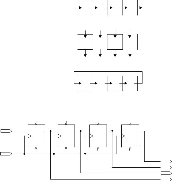
a. Serial shifting
Q3 |
Q2 |
Q1 |
Q0 |
b. Parallel transfer
Q3 |
Q2 |
Q1 |
Q0 |
c. Rotation
FIGURE 9.57
Data Movement in a 4-bit Shift Register
|
DFF |
|
DFF |
|
DFF |
|
DFF |
|
INPUT |
PRN |
Q3 |
PRN |
Q2 |
PRN |
Q1 |
PRN |
Q0 |
Serial_in |
D |
Q |
D |
Q |
D |
Q |
D |
Q |
|
CLRN |
CLRN |
CLRN |
CLRN |
||||
INPUT |
|
|
|
|
|
|
|
|
Clock |
|
|
|
|
|
|
|
|
|
|
|
|
|
|
|
|
OUTPUT |
|
|
|
|
|
|
|
|
Q0 |
|
|
|
|
|
|
|
|
OUTPUT |
|
|
|
|
|
|
|
|
Q1 |
|
|
|
|
|
|
|
|
OUTPUT |
|
|
|
|
|
|
|
|
Q2 |
|
|
|
|
|
|
|
|
OUTPUT |
|
|
|
|
|
|
|
|
Q3 |
FIGURE 9.58
4-bit Serial Shift Register Configured to Shift Right
right and the bit at the circuit input is shifted into Q3. The bit stored in Q0 is overwritten by the former value of Q1 and is lost. Since the data move from left to right, we say that the shift register implements a right shift function. (Data movement in the other direction, requiring a different circuit connection, is called left shift.)
Let us track the progress of data through the circuit in two cases. All flip-flops are initially cleared in each case.
Case 1: A 1 is clocked into the shift register, followed by a string of 0s, as shown in Figure 9.59. The flip-flop containing the 1 is shaded.
Before the first clock pulse, all flip-flops are filled with 0s. Data In goes to a 1 and on the first clock pulse, the 1 is clocked into the first flip-flop. After that, the input goes to 0. The 1 moves one position right with each clock pulse, the register filling up with 0s behind it, fed by the 0 at Data In.After four clock pulses, the 1 reaches the Data Out flip-flop. On the fifth pulse, the 0 coming behind overwrites the 1 at Q0, leaving the register filled with 0s.

|
|
|
|
|
|
|
|
|
|
|
|
|
|
|
|
|
|
|
9.7 • |
Shift Registers |
415 |
|||||||
|
|
|
|
|
0 |
|
|
|
|
|
0 |
|
|
|
|
|
0 |
|
|
|
|
|
0 |
|
|
|
|
|
|
|
0 |
|
|
|
|
Q3 |
|
|
|
|
Q2 |
|
|
|
|
Q1 |
|
|
|
|
Q0 |
|
|||||
Data in |
D |
Q |
D |
Q |
D |
Q |
D |
Q |
Data out |
|||||||||||||||||||
|
|
|
|
|
|
|
|
|
||||||||||||||||||||
|
|
|
|
|
|
|
|
|
|
|
|
|
|
|
|
|
|
|
|
|
|
|
|
|
|
|||
|
|
|
|
|
|
|
|
|
|
|
|
|
|
|
|
|
|
|
|
|
|
|
|
|
|
|
|
|
|
|
|
|
|
|
Q |
|
|
|
|
|
Q |
|
|
|
|
|
Q |
|
|
|
|
|
Q |
|
|
|
|
Clock |
|
|
|
|
|
|
|
|
|
|
|
|
|
|
|
|
|
|
|
|
|
|
|
|
|
|
|
|
|
|
|
|
|
|
|
|
|
|
|
|
|
|
|
|
|
|
|
|
|
|
|
|
|
|
|
||
|
|
|
|
1 |
|
|
|
|
|
0 |
|
|
|
|
|
0 |
|
|
|
|
|
0 |
|
|
|
|
||
|
|
|
|
|
|
|
|
|
|
|
|
|
|
|
|
|
|
|
|
|
|
|
|
|||||
|
|
|
|
|
|
|
|
|
|
|
|
|
|
|
|
|
|
|
|
|
|
|
||||||
Data in |
|
|
D |
Q |
Q3 |
D |
Q |
Q2 |
D |
Q |
Q1 |
D |
Q |
Q0 |
Data out |
|||||||||||||
|
|
|
|
|
|
|
|
|||||||||||||||||||||
|
|
|
|
|
|
|
|
|
|
|
|
|
|
|
|
|
|
|
||||||||||
|
|
|
|
|
|
|
|
|
|
|
|
|
|
|
|
|
|
|
|
|
|
|
|
|
|
|
|
|
|
|
|
|
|
|
Q |
|
|
|
|
|
Q |
|
|
|
|
|
Q |
|
|
|
|
|
Q |
|
|
|
|
|
|
|
|
|
|
|
|
|
|
|
|
|
|
|
|
|
|
|
|
|
|
|
|
|
|
|
||
Clock |
|
|
|
|
|
|
|
|
|
|
|
|
|
|
|
|
|
|
|
|
|
|
|
|
|
|
|
|
|
|
|
|
0 |
|
|
|
|
|
1 |
|
|
|
|
|
0 |
|
|
|
|
|
0 |
|
|
|
|
||
|
|
|
|
|
|
|
|
|
|
|
|
|
|
|
|
|
|
|
|
|
|
|
|
|||||
|
|
|
|
|
|
|
|
|
|
|
|
|
|
|
|
|
|
|
|
|
|
|
||||||
Data in |
|
|
D |
Q |
Q3 |
D |
Q |
Q2 |
D |
Q |
Q1 |
D |
Q |
Q0 |
Data out |
|||||||||||||
|
|
|
|
|
|
|
|
|||||||||||||||||||||
|
|
|
|
|
|
|
|
|||||||||||||||||||||
|
|
|
|
|
|
|
|
|
|
|
|
|
|
|
|
|
|
|
||||||||||
|
|
|
|
|
|
|
|
|
|
|
|
|
|
|
|
|
|
|
|
|
|
|
|
|
|
|
|
|
|
|
|
|
|
|
Q |
|
|
|
|
|
Q |
|
|
|
|
|
Q |
|
|
|
|
|
Q |
|
|
|
|
|
|
|
|
|
|
|
|
|
|
|
|
|
|
|
|
|
|
|
|
|
|
|
|
|
|
|
||
Clock |
|
|
|
|
|
|
|
|
|
|
|
|
|
|
|
|
|
|
|
|
|
|
|
|
|
|
|
|
|
|
|
|
0 |
|
|
|
|
|
0 |
|
|
|
|
|
1 |
|
|
|
|
|
0 |
|
|
|
|
||
|
|
|
|
|
|
|
|
|
|
|
|
|
|
|
|
|
|
|
|
|
|
|
|
|||||
|
|
|
|
|
|
|
|
|
|
|
|
|
|
|
|
|
|
|
|
|
|
|
||||||
Data in |
|
|
D |
Q |
Q3 |
D |
Q |
Q2 |
D |
Q |
Q1 |
D |
Q |
Q0 |
Data out |
|||||||||||||
|
|
|
|
|
|
|
|
|||||||||||||||||||||
|
|
|
|
|
|
|
|
|||||||||||||||||||||
|
|
|
|
|
|
|
|
|
|
|
|
|
|
|
|
|
|
|
||||||||||
|
|
|
|
|
|
|
|
|
|
|
|
|
|
|
|
|
|
|
|
|
|
|
|
|
|
|
|
|
|
|
|
|
|
|
Q |
|
|
|
|
|
Q |
|
|
|
|
|
Q |
|
|
|
|
|
Q |
|
|
|
|
|
|
|
|
|
|
|
|
|
|
|
|
|
|
|
|
|
|
|
|
|
|
|
|
|
|
|
||
Clock |
|
|
|
|
|
|
|
|
|
|
|
|
|
|
|
|
|
|
|
|
|
|
|
|
|
|
|
|
|
|
|
|
0 |
|
|
|
|
|
0 |
|
|
|
|
|
0 |
|
|
|
|
|
1 |
|
|
|
|
||
|
|
|
|
|
|
|
|
|
|
|
|
|
|
|
|
|
|
|
|
|
|
|
|
|||||
|
|
|
|
|
|
|
|
|
|
|
|
|
|
|
|
|
|
|
|
|
|
|
||||||
Data in |
|
|
D |
Q |
Q3 |
D |
Q |
Q2 |
D |
Q |
Q1 |
D |
Q |
Q0 |
Data out |
|||||||||||||
|
|
|
|
|
|
|
|
|||||||||||||||||||||
|
|
|
|
|
|
|
|
|||||||||||||||||||||
|
|
|
|
|
|
|
|
|
|
|
|
|
|
|
|
|
|
|
||||||||||
|
|
|
|
|
|
|
|
|
|
|
|
|
|
|
|
|
|
|
|
|
|
|
|
|
|
|
|
|
|
|
|
|
|
|
Q |
|
|
|
|
|
Q |
|
|
|
|
|
Q |
|
|
|
|
Q |
|
|
|
||
Clock |
|
|
|
|
|
|
|
|
|
|
|
|
|
|
|
|
|
|
|
|
|
|
|
|
|
|
||
|
|
|
|
|
|
|
|
|
|
|
|
|
|
|
|
|
|
|
|
|
|
|
|
|
|
|||
|
|
|
|
|
|
|
|
|
|
|
|
|
|
|
|
|
|
|
|
|
|
|
|
|
|
|||
Case 2: Figure 9.60 shows a shift register, initially cleared, being filled with 1s.
As before, the initial 1 is clocked into the shift register and reaches the Data Out line on the fourth clock pulse. This time, the register fills up with 1s, not 0s, because the Data input remains HIGH.
Figure 9.61 shows a MAX PLUS II simulation of the 4-bit serial shift register in Figure 9.58 through 9.60. The first half of the simulation shows the circuit operation for Case

416 |
C H A P T E R 9 • Counters and Shift Registers |
|
|
|
|
|
|
|
|
|
|
|
|
|
|
|
|
|
|
|
|
||||||||
FIGURE 9.60 |
|
|
|
|
|
0 |
|
|
|
|
|
0 |
|
|
|
|
|
0 |
|
|
|
|
|
0 |
|
|
|
|
|
Filling a Shift Register with |
|
|
0 |
|
|
|
|
Q3 |
|
|
|
|
Q2 |
|
|
|
|
Q1 |
|
|
|
|
Q0 |
||||||
|
|
|
|
|
|
|
|
|
|
|
|
|
|
|
|
|
|
||||||||||||
“1”s (Shift Right) |
|
|
D |
Q |
D |
Q |
D |
Q |
D |
Q |
|||||||||||||||||||
Data in |
|
|
|
|
|
|
|
|
|
Data out |
|||||||||||||||||||
|
|
|
|
|
|
|
|
|
|
|
|||||||||||||||||||
|
|
|
|
|
|
|
|
|
|
|
|
|
|
|
|
|
|
|
|
|
|
|
|
|
|
|
|
||
|
|
|
|
|
|
|
|
|
|
|
|
|
|
|
|
|
|
|
|
|
|
|
|
|
|
|
|
|
|
|
|
|
|
|
|
|
|
Q |
|
|
|
|
|
Q |
|
|
|
|
|
Q |
|
|
|
|
|
Q |
|
|
|
|
|
Clock |
|
|
|
|
|
|
|
|
|
|
|
|
|
|
|
|
|
|
|
|
|
|
|
|
|
|
|
|
|
|
|
|
|
|
|
|
|
|
|
|
|
|
|
|
|
|
|
|
|
|
|
|
|
|
|
|
|
|
|
|
|
|
|
1 |
|
|
|
|
|
0 |
|
|
|
|
|
0 |
|
|
|
|
|
0 |
|
|
|
|
|
|
|
|
|
|
|
|
|
|
|
|
|
|
|
|
|
|
|
|
|
|
|
|
|
|
|
||||
|
|
|
|
1 |
|
|
|
|
|
|
|
|
|
|
|
|
|
|
|
|
|
|
|||||||
|
|
|
|
D |
Q |
Q3 |
D |
Q |
Q2 |
D |
Q |
Q1 |
D |
Q |
Q0 |
||||||||||||||
|
|
Data in |
|
|
|
|
|
|
|
|
Data out |
||||||||||||||||||
|
|
|
|
|
|
|
|
|
|
||||||||||||||||||||
|
|
|
|
|
|
|
|
|
|
|
|
|
|
|
|
|
|
|
|
|
|||||||||
|
|
|
|
|
|
|
|
|
|
|
|
|
|
|
|
|
|
|
|
|
|
|
|
|
|
|
|
|
|
|
|
|
|
|
|
|
|
Q |
|
|
|
|
|
Q |
|
|
|
|
|
Q |
|
|
|
|
|
Q |
|
|
|
|
|
|
|
|
|
|
|
|
|
|
|
|
|
|
|
|
|
|
|
|
|
|
|
|
|
|
|
|
|
|
|
Clock |
|
|
|
|
|
|
|
|
|
|
|
|
|
|
|
|
|
|
|
|
|
|
|
|
|
|
|
|
|
|
|
|
|
1 |
|
|
|
|
|
1 |
|
|
|
|
|
0 |
|
|
|
|
|
0 |
|
|
|
|
|
|
|
|
|
|
|
|
|
|
|
|
|
|
|
|
|
|
|
|
|
|
|
|
|
|
|
||||
|
|
|
|
1 |
|
|
|
|
|
|
|
|
|
|
|
|
|
|
|
|
|
|
|||||||
|
|
|
|
D |
Q |
Q3 |
D |
Q |
Q2 |
D |
Q |
Q1 |
D |
Q |
Q0 |
||||||||||||||
|
|
Data in |
|
|
|
|
|
|
|
|
Data out |
||||||||||||||||||
|
|
|
|
|
|
|
|
|
|
||||||||||||||||||||
|
|
|
|
|
|
|
|
|
|
|
|
|
|
|
|
|
|
|
|
|
|||||||||
|
|
|
|
|
|
|
|
|
|
|
|
|
|
|
|
|
|
|
|
|
|
|
|
|
|
|
|
|
|
|
|
|
|
|
|
|
|
Q |
|
|
|
|
|
Q |
|
|
|
|
|
Q |
|
|
|
|
|
Q |
|
|
|
|
|
|
|
|
|
|
|
|
|
|
|
|
|
|
|
|
|
|
|
|
|
|
|
|
|
|
|
|
|
|
|
Clock |
|
|
|
|
|
|
|
|
|
|
|
|
|
|
|
|
|
|
|
|
|
|
|
|
|
|
|
|
|
|
|
|
|
1 |
|
|
|
|
|
1 |
|
|
|
|
|
1 |
|
|
|
|
|
1 |
|
|
|
|
|
|
|
|
|
|
|
|
|
|
|
|
|
|
|
|
|
|
|
|
|
|
|
|
|
|
|
||||
|
|
|
|
1 |
|
|
|
|
|
|
|
|
|
|
|
|
|
|
|
|
|
|
|||||||
|
|
|
|
D |
Q |
Q3 |
D |
Q |
Q2 |
D |
Q |
Q1 |
D |
Q |
Q0 |
||||||||||||||
|
|
Data in |
|
|
|
|
|
|
|
|
Data out |
||||||||||||||||||
|
|
|
|
|
|
|
|
|
|
||||||||||||||||||||
|
|
|
|
|
|
|
|
|
|
|
|
|
|
|
|
|
|
|
|
|
|||||||||
|
|
|
|
|
|
|
|
|
|
|
|
|
|
|
|
|
|
|
|
|
|
|
|
|
|
|
|
|
|
|
|
|
|
|
|
|
|
Q |
|
|
|
|
|
Q |
|
|
|
|
|
Q |
|
|
|
|
|
Q |
|
|
|
|
|
|
|
|
|
|
|
|
|
|
|
|
|
|
|
|
|
|
|
|
|
|
|
|
|
|
|
|
|
|
|
Clock |
|
|
|
|
|
|
|
|
|
|
|
|
|
|
|
|
|
|
|
|
|
|
|
|
|
|
|
|
|
|
|
|
|
|
|
|
|
|
|
|
|
|
|
|
|
|
|
|
|
|
|
|
|
|
|
|
|
FIGURE 9.61
Simulation of a 4-bit Shift
Register (Shift Right)


