


DOE-HDBK-1092-98
6.0 REQUIREMENTS FOR SPECIFIC EQUIPMENT
The electrical safety requirements for specific equipment are determined by the following standards:
1.NFPA 70, National Electrical Code (NEC)
2.29 CFR 1910, Occupational Safety and Health Standards
3.29 CFR 1926, Safety and Health Regulations for Construction.
4.NFPA 70E, Standard for Electrical Safety Requirements for Employee Workplaces.
29 CFR 1910 and 1926 frequently reference other safety guidelines for design, operation, and maintenance. Such other guidelines comprise ANSI, ASTM and IEEE specifications and information derived from various engineering sources or equipment manufacturer association standards. However, the key document is NFPA 70, the NEC; all the other documents are keyed to it. The NEC reflects wiring and installation requirements that provide for a safe electrical system.
6.1 CONVEYING SYSTEMS
Conveying systems are used to move materials, goods, etc., from one place to another. Because of their conditions of use, they are usually classified in service applications as intermittent duty per NEC Tables 430-22(a) and 620-15.
6.1.1GENERAL DESIGN, INSTALLATION, MAINTENANCE, AND INSPECTION REQUIREMENTS
The general design criteria for elevators, dumbwaiters, wheelchair lifts, escalators, and cranes should comply with:
1.ASME/ANSI A17.1, Safety Code for Elevators and Escalators
2.NFPA 70, National Electrical Code
3.ANSI C-2, National Electrical Safety Code (NESC)
4.Uniform Building Code, Chapter 51 (except enclosures)
5.29 CFR 1910, Occupational Safety and Health Standards
6.29 CFR 1926, Safety and Health Regulations for Construction
7.Uniform Federal Accessibility Standard (UFAS), Handicapped Wheelchair Lifts
6-1

DOE-HDBK-1092-98
8.National Electrical Manufacturers Association (NEMA) Standards
9.NFPA 101, Life Safety Code, Chapters 6 and 7
10.Crane Manufacturers Association of America (CMAA)-70, Specifications for Electrical Overhead Traveling Cranes
11.CMAA-74, Specifications for Top Running and Under Running Types of Single Girder Electric Overhead Traveling Cranes
All conveying systems shall be suited to the occupancy requirements of the location where they are installed. Where they penetrate a security barrier, they shall provide the same degree of penetration resistance and intrusion detection as is required by the site-specific security plan.
Additional applicable codes and standards for maintenance and inspection are listed below and provide an overview of electrical and maintenance and inspection requirements.
1.CMAA Crane Operators’ Manual
2.CMAA Overhead Crane and Inspection Checklist
3.ANSI/ASME B30.2, Overhead and Gantry Cranes
4.ANSI/ASME B30.11, Monorail Systems and Underhung Cranes
5.ANSI/ASME B30.16, Overhead Hoists
6.ANSI/ASME A17.2.1, “Inspectors Manual for Electric Elevators.” ANSI/ASME A17.2.2, “Inspectors Manual for Hydraulic Elevators.” ANSI/ASME A17.2.3, “Inspectors Manual for Escalators and Moving Walks.”
7.ANSI/ASME A17.3, Safety Code for Existing Elevators and Escalators.
6.1.2 ELECTRICAL DESIGN CRITERIA
Electrical design criteria should be closely coordinated with the architect, structural engineer, fire protection engineer, mechanical engineer, and electrical safety engineer to ensure that all discipline requirements are coordinated and met.
Factory and field performance tests and control and wiring diagrams should be specified in the purchase order or contract because they are not otherwise provided by the factory. Acceptance tests conducted by the factory representative, qualified independent inspector, or engineer are recommended. Tests conducted by Underwriters Laboratory (UL) and Factory Mutual Engineering Corporation (FM) are also acceptable.
6-2

DOE-HDBK-1092-98
ANSI and CMAA standards should be carefully reviewed to ensure that all applicable safety requirements are covered in the specifications.
The designer should specify the following requirements:
1.Available system voltage
2.Control voltage
3.The motor is constructed for the specific application
4.Motor horsepower, service factor, insulation class, and time ratings are sufficient to meet the load requirements
5.Working clearances and space requirements
6.Disconnecting means and other NEC requirements.
6.2CRANES AND HOISTS
The most significant factor in crane and hoist safety, after structural integrity, is electrical safety. All the referenced standards support this fact either directly or indirectly by the amount of definition and space provided for electrical systems’ controls, operations, and maintenance.
6.2.1 NEC GENERAL REQUIREMENTS
Basic installation and wiring safety requirements for cranes and hoists are given in NEC Article 6101. Electrical designers and maintenance personnel should thoroughly understand these requirements and their intent. Some of the more significant requirements are the following:
1.Cranes and hoists operated in hazardous (classified) locations shall conform to NEC Article 500.
2.When the crane is operated above readily combustible materials, the resistors must be located in a well-ventilated cabinet constructed of noncombustible material and constructed so that they will not emit flames or molten metal. See the exception (and requirements) that applies to certain cabinets made of noncombustible materials.
3.Cranes and hoists operating on electrolytic cell lines have special requirements, as given in NEC Section 668-32.
a.Grounding is not required for conductive surfaces of cranes and hoists that enter the working zone of a cell line, and the parts that come in contact with an energized cell or attachments shall be insulated from ground.
1 See Appendix D, Reference Matrix.
6-3

DOE-HDBK-1092-98
b.Remote controls that may introduce hazardous conditions into the cell line working zone shall employ one or more of the following:
(1)Isolated and ungrounded control circuit in compliance with NEC Section 668-21(a)
(2)Nonconductive rope operator
(3)Pendant pushbutton with either non-conductive support and surfaces or ungrounded exposed surfaces.
(4)Radio
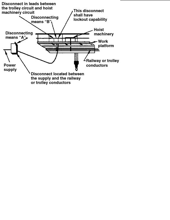
6.2.2DISCONNECTING MEANS
The disconnecting means provided for cranes and hoists may consist of two or more lock-open-type motor circuit switches or circuit breakers. Article 610, Part D, of the NEC, “Disconnecting Means,” and the installation and operating plans should be studied carefully to determine the disconnecting means requirements and locations. The two basic disconnects to consider are:
1.The runway conductor (conductors run along a crane runway for power or control) disconnect which shall:
a.Be readily accessible or operable from the ground or floor level per NEC Section 61031(1)
b.Be lockable in the open position per NEC Section 610-31(2)
c.Open all ungrounded conductors simultaneously per NEC Section 610-31(3)
d.Be placed in view of the crane or hoist and the runway conductors per NEC Section 61031(4).
2.The crane and hoist disconnect which shall be provided in the leads from the runway contact conductors or other power supply unless all the following requirements are met:
a.The unit is ground or floor level controlled per NEC Section 610-32, Exception
b.The unit is within view of the power supply disconnecting means per NEC Section 61032, Exception
c.No fixed work platform has been provided for servicing the unit per NEC Section 61032, Exception.
See Figure 6-1 (a) and (b) for a detailed illustration of the rules pertaining to the disconnecting means for electric cranes and hoists.
6-4
DOE-HDBK-1092-98
NEC Sections 610-31 and 610-32
OSHA Section 29 CFR 1910.306 (b) (1 ) (ii) (A)
Figure 6-1 (a). An additional control switch or a remote control switch is required if the second disconnecting means is not accessible to the operator.
NEC Sections 610-31 and 610-32
OSHA Section 29 CFR 1910.306 (b) (1 ) (ii) (B)
Figure 6-1 (b). Second disconnect not required. A monorail hoist does not require a disconnecting means in the leads to the hoist machinery if it is controlled from the floor, if it is within view of the power supply disconnect, and if there is no work platform provided to service the hoist machinery.
6-5

DOE-HDBK-1092-98
6.2.3 GROUNDING
NEC grounding requirements consider the crane or hoist with all its associated equipment, including electrical equipment, as a single piece of equipment; therefore, all the conductive component parts shall be bonded together so that the entire crane or hoist is grounded in compliance with NEC Article 250, Part G, and NEC Section 610-61. Metal-to-metal contact is required between all surfaces including the trolley wheels and bridge. If any such surfaces are painted or otherwise insulated, a separate bonding conductor is required.
The bonding of all conductive surfaces by metal-to-metal contact is not to be considered as the equipment grounding conductor for the electrical equipment (motors, motor controllers, lighting fixtures, transformers, etc.)on the crane or hoist. The equipment ground conductors that are run with the circuit conductors shall comply with NEC Section 250-91(b).
6.2.4 CONTROL
A limit switch is required to prevent the load block from passing the safe upper travel limit on all hoisting mechanisms per NEC Section 610-55.
6.2.5 CLEARANCES
In the direction of live parts, the working space clearance is 2-1/2 ft, and doors enclosing live parts that may require service or maintenance shall open at least 90 degrees or be removable per NEC Section 610-57.
6.2.6 OSHA AND NEC REQUIREMENTS
29 CFR 1910.179 and NEC Article 610, Part F, provide additional electrical requirements derived from ANSI and other standards. Significant requirements are the following:
1.Control circuit voltage shall not exceed 600 Vac or dc. Pendant pushbutton voltage shall not exceed 150 Vac or 300 Vdc.
2.Support shall be provided for pendant multiconductor cables.
3.Electrical systems for cranes and hoists shall provide failsafe operation. When power fails, all motors shall be automatically disconnected so that they will not resume operation when the power comes back on. Automatic cranes shall not commence motion automatically when the power comes on after an outage. Pendant pushbuttons shall be returned to the off position when pressure is released. When the signal from a remote controller fails, all motion shall stop.
6.2.7 MAINTENANCE AND OPERATIONS
It is important to have a comprehensive electrical maintenance program for cranes and hoists. Every electrical part and circuit plays a critical operational safety role and must be checked and serviced at the frequency and in the manner specified by OSHA, CMAA, ANSI, and the manufacturer’s
6-6

DOE-HDBK-1092-98
manual. Required weekly, monthly, and semiannual tests and required recordkeeping are contained in ANSI B-30 and CMAA documents.
The basic references for safe operation and maintenance of cranes and hoists are contained in the following sections of 29 CFR 1910 and 1926.
1.29 CFR 1910.179, Overhead and Gantry Cranes, which addresses operations and maintenance requirements
2.29 CFR 1910.306, Specific Purpose Equipment and Installations, which address electrical installation requirements
3.29 CFR 1926.550 and 29 CFR 1926.554, which address construction site operations.
6.2.8 DOCUMENTED MAINTENANCE
Maintenance checklists and schedules in compliance with OSHA, the owner’s manuals, and the manufacturer’s requirements for the specific equipment shall be provided as required. Weekly, monthly, and semiannual inspections shall be conducted, and comments and condition of the inspected part shall be documented and certified as required by 29 CFR 1910.179.
The recommended frequencies of inspections vary in accordance with application, usage, and authority. Frequent inspection and periodic inspection are defined by OSHA as daily to monthly and 1 to 12 months, respectively. Typical inspection frequencies for electrical equipment of cranes and hoists are as follows:
Weekly |
Monthly |
Semiannually |
Brakes |
Control Operations |
Motors |
Pushbuttons |
Collectors |
Control Panel |
Master |
Resistors |
|
Switch |
Conductors |
|
Mainline |
|
|
Disconnect |
|
|
Warning |
|
|
Device |
|
|
|
|
|
The inspection records shall provide an ongoing safety assessment of the equipment and be used to predict repair-part replacement. All inspections shall be dated and initialed by the inspector.
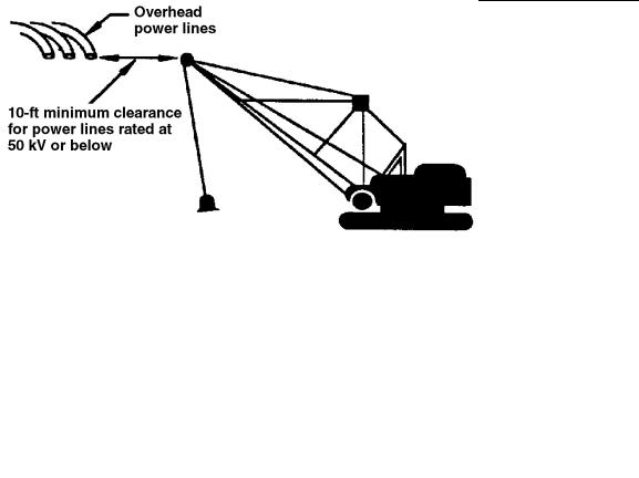
6.2.9 MECHANICAL ELEVATING AND ROTATING EQUIPMENT
The primary electrical safety concern of 29 CFR 1910.269(p)(4) and 1926.550 is work in proximity to live and unguarded electrical overhead lines by uninsulated equipment. Unless these lines are visibly grounded at the point of work and the owner of the lines indicates that they are deenergized, barriers or insulating protective material shall be installed to prevent worker contact with them. The following clearances shall be maintained between equipment and electrical overhead lines:
6-7
DOE-HDBK-1092-98
1.Lines 50 kV or below: 10 ft between the lines and any part of the equipment or load
2.Lines over 50 kV: 10 ft plus 0.4 in. for every 1 kV above 50 kV.
In locations and situations where it is possible that the operator may have difficulty observing that these clearances are being maintained, someone shall be designated to monitor the clearances and provide the operator with timely warning before contact can be made. The use of cage-type boom guards, insulating links, or a proximity sensor shall not alter the electrical safety requirements of 29 CFR 1910.269(p)(4) and 1926.550, even if these devices are required. (See Figure 6-2.)
OSHA Sections 29 CFR 1910.269(p)(4), 1926.952 (b)
NFPA 70E Part ll, CH 1, B (2) (i) (1); (2)
Figure 6-2. A minimum clearance of 10 ft between overhead power lines and equipment is required for 50 kV and below while a clearance of 10 ft plus 4 in. for every kV above 50 kV is required.
6.3 ELEVATORS AND ESCALATORS
Elevators and escalators are used to move people and elevators are also used to move materials. Design, installation, inspection, and maintenance activities require specialized knowledge for safe operation and use.
6.3.1 CODES AND STANDARDS
A comprehensive electrical safety program for elevators and escalators can be achieved through the application of the guidelines in the following five standards:
1.ANSI/ASME A17.1, Safety Code for Elevators and Escalators
2.ANSI/ASME A17.2.1, “Inspectors Manual for Electric Elevators.” ANSI/ASME A17.2.2, “Inspectors Manual for Hydraulic Elevators.” ANSI/ASME A17.2.3, “Inspectors Manual for Escalators and Moving Walks.”
3.ANSI/ASME A17.3, Safety Code for Existing Elevators and Escalators.
6-8
DOE-HDBK-1092-98
All elevators are required to be constructed, installed, and maintained in accordance with ANSI/ ASME A17.1. Reference standards include NFPA 70 (NEC) for the electrical equipment wiring and NFPA 101 (Life Safety Code), Chapter 6, Features of Fire Protection, and Chapter 7, Building Service and Fire Protection Equipment. These standards reflect the interrelated roles of electrical design, maintenance, and fire protection in the electrical safety process.
6.3.2 DESIGN SPECIFICATIONS
The electrical designer shall provide for the installation requirements of Article 620 of the NEC as well as the ANSI/ASME A17.1 requirements of Sections 102, 210, and 211 for signaling, automatic fire protection, and emergency power as required. The manufacturer shall provide the required fire service key switches, audible alarm devices, and internal wiring up to the terminal strips in the elevator control panel.
6.3.2.1 VOLTAGE AND CURRENT LIMITATIONS
There shall be a 300-V limitation on all operating control and signal circuits and related equipment, including door operators. Exceptions are permitted for 25 to 60 Hz ac if the current cannot under any conditions exceed 8 mA, or for dc voltage if the current cannot, under any circumstances, exceed 30 mA.
6.3.2.2 CONDUCTORS
Hoistway door conductors from the door interlocks to the hoistway riser shall be flame retardant, suitable for a temperature of at least 200°C, and Type SF or equivalent. See Table 400-4 of the NEC
for approved types of elevator cables and Note 5 to Table 400-4 concerning special requirements for traveling control and signal cables. Operating control and signal cable conductors may be as small as #24 AWG. Traveling cable conductors must be #20 AWG or larger. (See NEC Sections 620-11 and 12).
6.3.2.3 DISCONNECTING MEANS
The disconnecting means requirements for elevators and escalators are both specific and extensive, requiring careful study of the codes and installation plans during design, acceptance testing, and routine inspections. Some of the basic requirements of NEC Section 620-51 are the following:
1.There shall be a single means of disconnecting all ungrounded conductors to the main power supply of each unit.
2.A single elevator or escalator, with multiple driving machines, shall have one disconnecting means to disconnect the motors and control valve operating magnets.
3.When there is more than one driving machine in a machine room, the disconnecting means shall be labeled per NEC Section 620-51 and 29 CFR 1910.303(f).
4.The disconnect shall be a fused motor circuit switch or circuit breaker capable of being locked open.
6-9

DOE-HDBK-1092-98
5.The disconnect shall not be provided with a means of being operated from a remote location.
6.A circuit breaker disconnecting means shall not be opened automatically by a fire alarm system, except as allowed by NEC Section 620-51(b).
7.The within-sight rule applies to all elevator equipment disconnects. Specific locations are given for elevators with or without field control.
8.The disconnecting means shall be installed in a location that is readily accessible to only qualified persons.
When power from more than one source is used for singleor multiple-car installations, a separate disconnect should be provided for each source. These disconnects should be in sight of the equipment supplied, and warning signs should be placed on or adjacent to the disconnect to read. For example, “Warning: Parts of the control panel are not deenergized by this switch.”
Lighting circuits for each elevator require a disconnect switch in the equipment room labeled for the car it serves and lockable in the open position.
6.3.2.4 MOTORS
Elevator and escalator motors are considered as intermittent duty. This allows them to be protected by the overcurrent protection device supplying the power for the branch circuit, which is selected by the percentages in NEC Table 430-22(a) times the full load current of the motors. For example: What is the load for a 15-minute rated 40-hp, 460-V, three-phase motor used as a freight elevator motor?
Step 1: Finding full load current—NEC Table 430-150
40 HP = 52 A
Step 2: Finding demand factors— NEC Table 430-22(a) 15 minute rated = 85%
Step 3: Calculating load
52 A x 85% = 44.2 A
Answer: Load is 44.2 amps.
6.3.2.5 GROUNDING
All metal raceways and cables, Types MC, MI, or AC, shall be bonded to the metal frame of the car. All elevator equipment including metal enclosures for electric devices on the car shall be grounded in accordance with NEC Article 250.
6-10

DOE-HDBK-1092-98
6.3.2.6 OVERSPEED PROTECTION
Overspeed protection for overhauling and under-hauling is required, as are motor-generator overspeed requirements that must comply with NEC Section 430-89, Speed Limitation. However, these requirements are a part of the more extensive requirements of ANSI/ASME A17.1 for electrical safety devices, which require scrutiny by designers, maintenance personnel, and inspectors.
6.3.3 EMERGENCY POWER
Emergency power requirements are governed by ANSI/ASME A17.1 Rule 211.2, which requires that the regenerative power of an overhauling elevator prevent the elevator from attaining the lesser of the governor tripping speed or 125% of rated speed. If the elevator power system cannot absorb this power, a load shall be provided on the load side of the elevator power disconnect switch. If an emergency power supply is designed to operate only one elevator at a time, the energy absorption means may, if required, be located on the line side of the disconnect. Other building loads that may be supplied by the emergency power source may not be considered as absorbing regenerated energy unless they use the emergency power source as normal power. Refer to Article 620, Part K, of the NEC, Overspeed, for the installation requirements covering these requirements.
6.3.4 DESIGN
In addition to the NEC, elevator and escalator requirements, there are numerous electrical requirements for the facilities designer in ANSI/ASME A17.1 and A17.3. ANSI/ASME A17.1 is a required reference for new elevator and escalator installations and can be used by the designer in checking submittal drawings from the manufacturer. ANSI/ASME A17.3 provides the safety requirements for existing elevators and escalators and shall be referenced when existing installations are to be modified or to determine which modifications shall be made to existing installations and equipment to maintain optimum safety. The following lists typical key electrical requirements from ANSI/ ASME A17.1 that the designer shall control over and above those from the NEC.
1.Access to elevator equipment is to be controlled and limited to authorized persons.
2.Elevator equipment cannot share space with other building equipment except when the elevator equipment is separated from other equipment, enclosed by a rigid wire fence, and provided with a lock that is strictly for that enclosure.
3.Only electrical wiring, including raceways and cables, used directly in connection with the elevator, including wiring for (a) signals, (b) communication with the car, (c) lighting, heating, air conditioning, and ventilating the car, (d) fire-detecting systems, (e) pit sump pumps, and (f) heating and lighting the hoistway may be installed in the hoistway.
4.A minimum lighting level of 108 lux for the equipment rooms and spaces and 54 lux on the floor of the pit is required. The basis for the specified illumination level should be in accordance with the Illuminating Engineering Society (IES) lighting handbook.
6-11

DOE-HDBK-1092-98
5.A stop switch (emergency stop) is required in each elevator pit at the access door to the pit. If the pit exceeds 6 ft, 7 in., a second switch is required adjacent to the ladder. The two switches will be connected in series. See ANSI/ASME A17.1, Section 210.
6.Car lighting shall consist of a minimum of two lamps to be supplied by a dedicated circuit with a lock-open disconnect in the equipment room.
7.A 115-V, 20-A receptacle shall be provided in all equipment spaces and in the pit.
8.A phase-reversal protection shall be provided to ensure that the elevator motor cannot start if the phase rotation is in the wrong direction or if there is a failure of any phase.
9.Capacitors and other devices whose failure could cause unsafe elevator operation are prohibited; only devices specified by the NEC or the manufacturer may be installed.
6.3.5 FIRE PROTECTION
The electrical designer shall coordinate with the manufacturer the design of the fire protection systems that connect to the elevator control panel. The system will be designed to return the car to a designated area (normally the first floor or lobby) in the event of smoke or fire in the equipment area or near the elevators. In that event, the car returns to a designated area where passengers can safely exit the facility. In addition to coordinating car control, the system provides for the shutdown of the electrical elevator equipment prior to operation of the sprinklers and the transmission of the alarm and provides a means for the firefighters to assume manual control of the elevator from the designated area. The requirements for these systems are detailed in ANSI/ASME A17.1, Section 211, “Emergency Operation and Signaling Devices.”
6.3.6 INSPECTIONS AND RECORDS
Elevator inspections and recordkeeping are performed in accordance with the local authority having jurisdiction. The ANSI/ASME A17.2 series of inspectors manuals provide a guide for performing tests and inspections as well as recommended inspection checklists. In addition to acceptance inspections and tests, the code requires 1-and 5-year inspections for electric elevators and 1-and 3- year inspections for hydraulic elevators.
6.3.6.1 CODES
Elevators are required to be in compliance with the issue of ANSI/ASME A17.1 in force the date they were installed. If the local authority has adopted ANSI/ASME A17.3, the code for existing installations, they shall be in compliance with it, except they shall not be downgraded to it. When ANSI/ASME A17.3 is in force, it becomes the minimum standard to which installations shall adhere, and if existing installations are upgraded in accordance with ANSI/ASME A17.1, Part XII, they shall also be in compliance with the more stringent requirements of A17.3.
6-12

DOE-HDBK-1092-98
6.3.6.2 INSPECTOR QUALIFICATIONS
Inspectors should meet the requirements of ANSI/ASME QEI-1 and be recognized by the local enforcing authority. Repair and maintenance personnel should be qualified elevator mechanics.
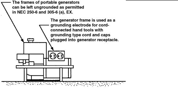
6.4 PORTABLE AND VEHICLE-MOUNTED GENERATORS
Using portable and vehicle-mounted generators to operate electric tools on job sites is permitted under specific conditions by both NEC Section 305-6 and 29 CFR 1926.404(f)(3).
However, OSHA inspections have disclosed a potentially serious hazard resulting from the use of portable generators. Both OSHA and the NEC permit the use of two-wire, single-phase generators of not more than 5,000 W “where the circuit conductors of the generator are insulated from the generator frame and all other grounded surfaces.” Under these conditions, neither the receptacles, cord sets, nor tools need to be protected by GFCIs or an assured equipment grounding conductor program. This exception from using GFCIs is granted because with an insulated (isolated) circuit, there is no dangerous current flow from the generator-fed conductors to ground, structural steel, or any other grounded object. However, the use of GFCI devices is still recommended.
If the circuit conductors are not isolated, however, the shock hazard would be the same as with any other electrical source and the exemption does not apply.
All portable electric generators that supply 15-or 20-A, 120-V receptacles and that are in use or are available for use on construction sites shall meet all the following conditions or be used only with either GFCIs or an assured equipment grounding conductor program.
1.They must be rated not more than 5 kW.
2.They shall have only a two-wire circuit (i.e., only 120-V output).
3.They shall have both circuit conductors insulated from the frame and all other grounded surfaces.
See NEC Section 250-6 and Figure 6-3.
6.5 BATTERIES
Storage batteries are considered a live source and appropriate precautions should be taken when working around them.
6.5.1 SURROUNDING SPACE
Adequate space should be provided around storage batteries for safe inspection, maintenance, testing, and cell replacement. Space shall be left above cells to allow for operation of lifting equipment when required, for addition of water, and for taking measurements.
6-13
DOE-HDBK-1092-98
NEC Sections 250–6; 305-6
Figure 6-3. The ungrounded frame of a generator is acceptable as a grounding electrode if the circuit conductors are insulated from the frame and all other grounded surfaces.
6.5.2 LOCATION
Storage batteries should be located in a protective enclosure or area accessible only to qualified persons. A protective enclosure can be a battery room; a control building; or a case, cage, or fence that shall protect the contained equipment and minimize the possibility of inadvertent contact with energized parts.
6.5.3 VENTILATION
The battery storage area shall be ventilated by either a natural or powered ventilation system to prevent accumulation of hydrogen. The ventilation system shall limit hydrogen accumulation to less than an explosive level. See NESC, Rules 14, and 120G, for inspection information and rules concerning gel-type and lead-acid batteries.
6.5.4 CONDUIT
Because the vapors given off by a storage battery are very corrosive, the wiring shall withstand the corrosive action, and special precautions are necessary as to the type of insulation used and the protection of all metalwork. It is stated by their respective manufacturers that conduit made of aluminum or silicon-bronze is well suited to withstand the corrosive effects of the vapors in battery rooms. In contrast, if steel conduit is used, it is recommended that it be zinc-coated and kept well painted with asphaltum paint.
6-14
DOE-HDBK-1092-98
6.5.5 BATTERY ROOM
There are no special requirements for the type of fixtures or other electrical equipment used in the battery room, with proper ventilation. (See NEC 480-8 and Figure 6-4)
NEC Section 480-8
OSHA Section 29 CFR 1910.305 (j) (7)
Figure 6-4. With proper ventilation there are no special requirements for wiring and equipment installed in battery rooms per NEC 480-8.
6.5.6 PERSONAL PROTECTIVE EQUIPMENT
Personal protective equipment (PPE) capable of protecting employees from acid splashes shall be used by those working on or servicing batteries. The minimum acceptable PPE shall include acidresistant gloves, aprons, and chemical-splash goggles. A full-face shield may also be used; it shall not, however, be worn in place of goggles.
The design and use of PPE for wear when servicing batteries shall comply with the requirements of 29 CFR 1910.132, .133, and .136. See NESC, Rule 146 and IEEE 450, Section 4.2.2. For information on safety showers and eyewash stations, see 29 CFR l910.151(c) and 1910.178(g)(2).
6.5.7 TOOLS
Tools used for working on batteries shall be insulated or nonsparking.
6-15

DOE-HDBK-1092-98
6.5.8 STORAGE BATTERIES AND BATTERY BANKS
The following subsection covers rechargeable batteries used as a source of electrical energy. This category is not limited to batteries of a particular voltage and energy rating, since the nature of the associated electrical hazards is similar without regard to battery size; the severity of the hazard increases as the battery ratings increase.
6.5.8.1 TYPES OF HAZARDS
Some of the types of hazards associated with storage batteries and battery banks are listed as follows:
1.Accidental grounding of one polarity of a battery bank can create a hazardous voltage between the ungrounded polarity and ground.
2.Accidental shorting of the exposed terminals or cables of a battery can result in severe electric arcing, causing burns and electric shock to nearby personnel.
3.Hydrogen gas generated during battery charging can create fire, explosion, and toxicity hazards.
4.Exposed terminals in a battery bank present electric shock hazards.
5.Batteries, particularly sealed-cell batteries, can explode if they are shorted or if they are charged at excessively high rates.
6.Electrolytes can be highly corrosive and can produce severe burns to personnel on contact.
6.5.8.2 DESIGN AND CONSTRUCTION CRITERIA
Reliable design and construction criteria for storage areas for batteries are as follows:
1.Battery installations shall conform to the requirements in the current edition of the NEC.
2.Battery banks should not be grounded except as required in NEC Section 250-3; a ground detector should be used to indicate an accidental ground.
3.Batteries should be mounted to allow safe and convenient access for maintenance.
4.Lockable doors should be provided to control access to rooms or enclosures containing battery banks.
5.Approved safety showers and eyewash stations should be provided close to battery banks.
6.Appropriate ventilation for discharges of gas should be provided.
7.In areas where seismic activity is present, the installation should be designed according to local standards.
6-16

DOE-HDBK-1092-98
6.5.8.3 OPERATING CRITERIA
Operating criteria are as follows:
1.Maintain battery bank connections that are clean and tight to prevent excessive heating because of contact resistance.
2.Do not repair battery connections when current is flowing. An accidental opening of the circuit could result in a hazardous arcing condition.
3.Clearly post electrical and other hazards of battery banks and emergency first aid information near the equipment.
4.Arrange the battery banks so that temperature stratification will not result in overor undercharging.
Note: The optimum storage temperature for maximum battery life is 77°F ± 2° (25°C ± 1).
6-17

DOE-HDBK-1092-98
This page left blank intentionally.
6-18
DOE-HDBK-1092-98
CONTENTS
7.0 WORK IN EXCESS OF 600 VOLTS ................................................................... |
7-1 |
||
7.1 |
RESPONSIBILITIES FOR SAFETY .......................................................... |
7-1 |
|
|
7.1.1 |
WORKERS .................................................................................... |
7-1 |
|
7.1.2 |
SUPERVISORS ............................................................................. |
7-2 |
7.2 |
TRAINING .................................................................................................. |
7-3 |
|
|
7.2.1 |
EMPLOYEE TRAINING ................................................................ |
7-3 |
|
7.2.2 |
QUALIFIED EMPLOYEE TRAINING ............................................ |
7-3 |
7.3 |
JOB BRIEFINGS ....................................................................................... |
7-3 |
|
7.4PERSONAL PROTECTIVE EQUIPMENT AND
PROTECTIVE CLOTHING ......................................................................... |
7-4 |
||
7.4.1 |
SHOES |
.......................................................................................... |
7-4 |
7.4.2 |
SAFETY HAT ................................................................................ |
7-4 |
|
7.4.3 |
EYE PROTECTORS ..................................................................... |
7-4 |
|
7.4.4 |
RESPIRATORS ............................................................................. |
7-5 |
|
7.4.5 |
METAL ...................................................................FASTENERS |
7-5 |
|
7.4.6 |
WORK GLOVES ........................................................................... |
7-5 |
|
7.4.7 |
WORK CLOTHES ......................................................................... |
7-5 |
|
7.4.8 |
FIRE RESISTANT .....................................................CLOTHING |
7-7 |
|
|
7.4.8.1 ..................................................................... |
GENERAL |
7-7 |
|
7.4.8.2 .......................................... |
ELECTRIC ARC HAZARDS |
7-7 |
|
7.4.8.3 ......................TYPES OF FIRE RESISTANT FABRICS |
7-7 |
|
|
7.4.8.4 .................................................. |
CLOTHING SYSTEMS |
7-8 |
7.4.9 |
RUBBER .......................................................................GLOVES |
7-8 |
|
7.4.10 RUBBER LINE HOSE, HOODS, COVERS, SLEEVES, |
|
||
|
AND BLANKETS .......................................................................... |
7-8 |
|
7.4.11 |
LIVE LINE ........................................................................TOOLS |
7-9 |
|
7.4.12 |
STOREROOM ............................................................STORAGE |
7-9 |
|
7.4.13 |
TRUCK .......................................................................STORAGE |
7-9 |
|
7.4.14 PLACING ........OF INSULATING GOODS ON CONDUCTORS |
7-10 |
||
7.4.15 REMOVING .....INSULATING GOODS FROM CONDUCTORS |
7-10 |
||
7.4.16 |
CLEANING ..................................................AND INSPECTING |
7-10 |
|
7.5 PROTECTIVE GROUNDING ..................OF LINES AND EQUIPMENT |
7-10 |
||
7.5.1 |
PURPOSE ................................................................................... |
7-10 |
|
7.5.1.1REDUCE THE POTENTIAL VOLTAGE DIFFERENCES
ACROSS THE WORKER ............................................ |
7-11 |
7.5.2 APPLICATION ............................................................................ |
7-12 |
7-1i

DOE-HDBK-1092-98
7.5.2.1 DEENERGIZED LINES ............................................... |
7-12 |
7.5.2.2NEW CONSTRUCTION OR DISMANTLING
OF FACILITIES ........................................................... |
7-12 |
7.5.2.3MINIMUM APPROACH DISTANCE FROM
UNGROUNDED CONDUCTORS ................................ |
7-12 |
7.5.2.4VISIBLE THREE-PHASE SHORT AND
|
GROUND REQUIRED ................................................. |
7-12 |
|
7.5.2.5 |
GROUND CIRCUIT ..................................................... |
7-12 |
|
7.5.3 GROUNDING EQUIPMENT ........................................................ |
7-13 |
||
7.5.3.1 |
AVAILABILITY ............................................................ |
7-13 |
|
7.5.3.2 |
APPROVED CAPACITY ............................................. |
7-14 |
|
7.5.3.3 GROUNDING CABLES AND HARDWARE ................ |
7-14 |
||
7.5.3.4 |
GROUNDING CABLES ............................................... |
7-14 |
|
|
7.5.3.4.1 |
STRANDING ............................................. |
7-14 |
|
7.5.3.4.2 |
JACKETS .................................................. |
7-14 |
|
7.5.3.4.3 |
FERRULES ............................................... |
7-14 |
|
7.5.3.4.4 HANDLING OF GROUNDING CABLE ..... |
7-15 |
|
|
7.5.3.4.5 SIZE OF GROUNDING CABLE ................ |
7-15 |
|
|
7.5.3.4.6 |
GROUNDING CABLE LENGTH ............... |
7-15 |
|
7.5.3.4.7 |
GROUNDING CLAMPS ............................ |
7-15 |
|
|
7.5.3.4.7.1 CLAMP TYPES ...................... |
7-15 |
|
|
7.5.3.4.7.2 CLAMP JAWS ....................... |
7-15 |
|
7.5.3.4.8 GROUNDING CLUSTER BARS ................. |
7-16 |
|
|
7.5.3.4.9 |
TEMPORARY GROUND RODS ............... |
7-16 |
7.5.4 TESTING BEFORE INSTALLING GROUNDS ........................... |
7-17 |
||
7.5.5 ATTACHING AND REMOVING GROUNDS .............................. |
7-17 |
||
7.5.6GROUNDING METHODS AND LOCATION OF
|
GROUNDS IN ORDER OF PREFERENCE ................................ |
7-17 |
|
|
7.5.6.1 |
WORK LOCATION ...................................................... |
7-17 |
|
7.5.6.2 MULTIPLE WORK LOCATIONS AND SINGLE-PHASE |
||
|
|
GROUNDING AT WORK LOCATION ......................... |
7-18 |
|
7.5.6.3 |
OTHER LOCATIONS .................................................. |
7-18 |
7.5.7 |
TESTING WITHOUT GROUNDS ................................................ |
7-18 |
|
7.5.8 |
GROUND PERSONNEL ............................................................. |
7-18 |
|
7.6 INSTALLING OR REMOVING CONDUCTORS ...................................... |
7-18 |
||
7.6.1 WORKING ON ENERGIZED LINE OR EQUIPMENT ................ |
7-18 |
||
7.6.2STRINGING OR REMOVING DEENERGIZED CONDUCTORS 7-19
7.6.3 STRINGING ADJACENT TO ENERGIZED LINES .................... |
7-21 |
|
7.7 SPECIAL TOOLS .................................................................................... |
7-21 |
|
7.7.1 |
LINEWORKER’S CLIMBING TOOLS ........................................ |
7-22 |
7.7.2 BODY BELTS AND SAFETY STRAPS ...................................... |
7-22 |
|
7.7.3 |
TOOL BAG AND EQUIPMENT .................................................. |
7-23 |
7--2ii

DOE-HDBK-1092-98
|
7.7.4 |
TAPES AND RULERS ................................................................ |
7-23 |
|
7.7.5 |
SPOON AND SHOVELS ............................................................. |
7-23 |
|
7.7.6 |
PIKE POLES ............................................................................... |
7-23 |
|
7.7.7 HAND AXES AND SHARP TOOLS ............................................ |
7-23 |
|
|
7.7.8 |
HANDLINES AND TAGLINES .................................................... |
7-24 |
7.8 |
TREE TRIMMING ..................................................................................... |
7-24 |
|
|
7.8.1 CARE AND USE OF TOOLS ...................................................... |
7-24 |
|
|
7.8.2 |
CLIMBING ................................................................................... |
7-24 |
7.9 |
SERIES STREET-LIGHTING CIRCUITS AND APPARATUS ................ |
7-24 |
|
7.10 |
UNDERGROUND ..................................................................................... |
7-25 |
|
|
7.10.1 WORKING IN MANHOLES, UTILITY TUNNELS, |
|
|
|
|
AND VAULTS ............................................................................. |
7-25 |
|
7.10.2 WORKING ON ENERGIZED UNDERGROUND CABLES ......... |
7-27 |
|
|
7.10.3 TERMINALS OF UNDERGROUND CABLES (POTHEADS) .... |
7-27 |
|
7.11 |
FERRO-RESONANCE ............................................................................. |
7-27 |
|
7--iii3

DOE-HDBK-1092-98
This page left blank intentionally.
7-4iv