


DOE-HDBK-1092-98
4.0 GROUNDING
This section presents general rules for the grounding and bonding of electrical installations. Qualified workers should clearly understand the concepts of grounding practices as required by the NEC. They should also clearly understand the definition and intent of the following components of a grounding system that are explained in this chapter:
1.Grounded conductor
2.Grounding conductor
3.Grounding electrode conductor
4.Bonding jumper
5.Grounding electrode.
4.1 REGULATIONS, CODES, AND REFERENCES
Regulations, codes, and references for system, equipment, and personal grounding can be found in the following documents:
1.29 CFR 1910
2.29 CFR 1926
3.National Electrical Code (NFPA 70)
4.National Electrical Safety Code (ANSI C2)
5.NFPA 70E
6.ASTM F855, “Specifications for Temporary Grounding Systems to be Used on Deenergized Electric Power Lines and Equipment”
7.DOD FIPS-PUB-94, “Guidelines on Electrical Power for ADP Installations”
8.DOD MIL-HDBK-419A, (Volumes 1 and 2) “Grounding, Bonding, and Shielding for Electronic Equipment and Facilities (Basic Theory, Applications)”
9.EIA/TIA-607, “Commerical Building Grounding and Bonding Requirements for Telecommunications”
10.IEEE 80, “Guide for Safety in AC Substation Grounding”
11.IEEE 142, “Recommended Practice for Grounding of Industrial and Commercial Power Systems”
12.IEEE 524A, “IEEE Guide to Grounding During the Installation of Overhead Transmission Line Conductors”
13.IEEE 1048, “IEEE Guide for Protective Grounding of Power Lines”
14.IEEE 1100, “Recommended Practice for Powering and Grounding Sensitive Electronic Equipment”
15.International Association of Electrical Inspectors, “Soares Book on Grounding”
16.NEMA 280, “Application Guide for Ground Fault Circuit Interrupters”
17.NEMA PB 2.2, “Application Guide for Ground Fault Protection Devices for Equipment”
4-1

DOE-HDBK-1092-98
4.1.1 ENGINEERING SPECIFICATIONS AND DRAWINGS
Engineering specifications and drawings should identify the requirements for all components and clearly illustrate the grounding electrode system, the grounding electrode conductor, bonding points and bonding jumpers, and the connection point for the grounded conductor and the grounding conductors. Where used for installation or construction purposes, these specifications and drawings should also include detailed installation instructions.
4.2 CIRCUIT AND SYSTEM GROUNDING
Circuit and system grounding consists of connecting the grounded conductor, the equipment grounding conductor, the grounding busbars, and all noncurrent-carrying metal parts to ground. This is accomplished by connecting a properly sized unspliced grounding electrode conductor between the grounding busbar and the grounding electrode system. There are three fundamental purposes for grounding an electrical system:
1.To limit excessive voltage from lightning, line surges, and crossovers with higher voltage lines.
2.To keep conductor enclosures and noncurrent-carrying metal enclosures and equipment at zero potential to ground.
3.To facilitate the opening of overcurrent protection devices in case of insulation failures because of faults, short circuits, etc. [See the fine-print note (FPN) to NEC Section 250-11.]
4.3 EQUIPMENT GROUNDING
Equipment grounding systems, which consist of interconnected networks of equipment grounding conductors, are used to perform the following functions:
1.Limit the hazard to personnel (shock voltage) from the noncurrent-carrying metal parts of equipment raceways and other conductor enclosures in case of ground faults, and
2.Safely conduct ground-fault current at sufficient magnitude for fast operation of the circuit overcurrent protection devices.
To ensure the performance of the above functions, equipment grounding conductors are required to:
1.Be permanent and continuous per NEC Sections 250-51, 250-75, 250-76, 250-77, 250-91, 300-10 and 300-12;
2.Have ample capacity to safely conduct ground-fault current likely to be imposed on them per NEC Table 250-94, Table 250-95, and Section 250-79(d) and (e); and
3.Have impedance sufficiently low to limit the voltage to ground to a safe magnitude and to facilitate the operation of the circuit overcurrent protection devices per NEC Sections 300-3(b) and 250-57(b).
1 See Appendix D, Reference Matrix.
4-2
DOE-HDBK-1092-98
4.4 BONDING
Caution shall be taken to ensure that the main bonding jumper and equipment bonding jumper are sized and selected correctly. Bonding completes the grounding circuit so that it is continuous. If a ground fault occurs, the fault current will flow and open the overcurrent protection devices. The means of bonding shall provide the following to ensure the grounding system is intact:
1.Provide a permanent connection,
2.Provide a positive continuity at all times, and
3.Provide ampacity to conduct fault current.
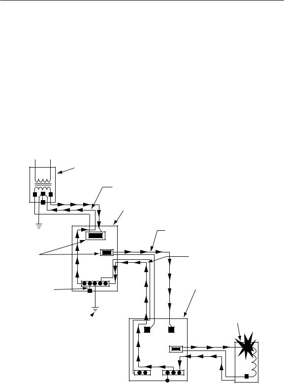
See Figure 4-1 on the proper grounding of electrical systems.
Supply |
|
|
transformer |
|
|
|
Grounded (neutral) conductor |
|
|
carrying fault current |
|
|
Service |
|
|
equipment |
|
|
Phase |
|
|
conductor |
|
Overcurrent |
This equipment grounding |
|
Protective |
||
conductor provides |
||
Device |
||
equipment grounding |
||
|
||
This conductor |
Subpanel |
|
provides the |
||
bonding of the |
|
|
equipment |
Equipment with |
|
|
ground fault |
|
This grounding electrode |
|
|
provides circuit and |
|
|
system grounding |
|
NEC Section 250-51
Figure 4-1. Circuit and system grounding consists of earth grounding the electrical system at the supply transformer and the line side of the service equipment. Equipment grounding and bonding is accomplished by connecting all metal enclosures and raceways together with the grounding conductors.
4-3

DOE-HDBK-1092-98
4.5 GROUNDED OR UNGROUNDED SYSTEMS
Ungrounded systems may provide greater continuity of operations in the event of a ground fault. However, the second fault will most likely be more catastrophic than a grounded system fault. Whenever ungrounded systems are used in a facility, the maintenance personnel should receive training in how to detect and troubleshoot the first ground on an ungrounded system.
Electrical systems can be operated grounded or ungrounded, depending on the condition of the systems’ use. Electrical systems are grounded to protect circuits, equipment, and conductor enclosures from dangerous voltages and personnel from electrical shock. See NEC Sections 110-9, 110-10, 230-65, 250-1, and 250-2 that list the requirements to provide this protection.
“Grounded” means that the connection to ground between the service panel and earth has bee n made. Ungrounded electrical systems are used where the designer does not want the overcurrent protection device to clear in the event of a ground fault.
Ground detectors can be installed per NEC Section 250-5(b) FPN to sound an alarm or send a message to alert personnel that a ground fault has occurred on one of the phase conductors. Ground detectors will detect the presence of leakage current or developing fault current conditions while the system is still energized and operating. By warning of the need to take corrective action before a problem occurs, safe conditions can usually be maintained until an orderly shutdown is implemented.
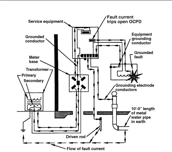
4.5.1 GROUNDED SYSTEMS
Grounded systems are equipped with a grounded conductor that is required per NEC Section 25023(b) to be run to each service disconnecting means. The grounded conductor can be used as a current-carrying conductor to accommodate all neutral related loads. It can also be used as an equipment grounding conductor to clear ground faults per NEC Section 250-61(a).
A network of equipment grounding conductors is routed from the service equipment enclosure to all metal enclosures throughout the electrical system. The equipment grounding conductor carries fault currents from the point of the fault to the grounded bus in the service equipment where it is transferred to the grounded conductor. The grounded conductor carries the fault current back to the source and returns over the faulted phase and trips open the overcurrent protection device.
Note: A system is considered grounded if the supplying source such as a transformer, generator, etc., is grounded, in addition to the grounding means on the supply side of the service equipment disconnecting device per NEC Sections 250-23(a) or 250-26 for seperately derived systems.
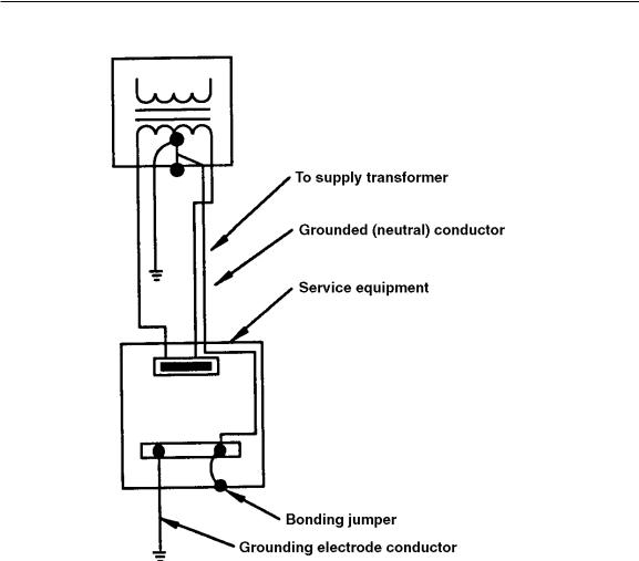
The neutral of any grounded system serves two main purposes: (1) it permits the utilization of line- to-neutral voltage and thus will serve as a current-carrying conductor to carry any unbalanced current, and (2) it plays a vital role in providing a low-impedance path for the flow of fault currents to facilitate the operation of the overcurrent devices in the circuit. (See Figure 4-2.) Consideration should be given to the sizing of the neutral conductor for certain loads due to the presence of harmonic currents (See NEC Sections 210-4 and 310-10).
4-4
DOE-HDBK-1092-98
NEC Section 250-50 (a)
OSHA Section 29 CFR 1910.304 (f) (3)
Figure 4-2. A grounded system is equipped with a grounded (neutral) conductor routed between the supply transformer and the service equipment.
4.5.2 UNGROUNDED SYSTEMS
Ungrounded systems operate without a grounded conductor. In other words, none of the circuit conductors of the electrical system are intentionally grounded to an earth ground such as a metal water pipe, building steel, etc. The same network of equipment grounding conductors is provided for ungrounded systems as for solidly grounded electrical systems. However, equipment grounding conductors (EGCs) are used only to locate phase-to-ground faults and sound some type of alarm. Therefore, a single sustained line-to-ground fault does not result in an automatic trip of the overcurrent protection device. This is a major benefit if electrical system continuity is required or if it would result in the shutdown of a continuous process. However, if an accidental ground fault occurs and is allowed to flow for a substantial time, overvoltages can develop in the associated phase conductors. Such an overvoltage situation can lead to conductor insulation damage, and while a ground fault remains on one phase of an ungrounded system, personnel contacting one of the other
4-5
DOE-HDBK-1092-98
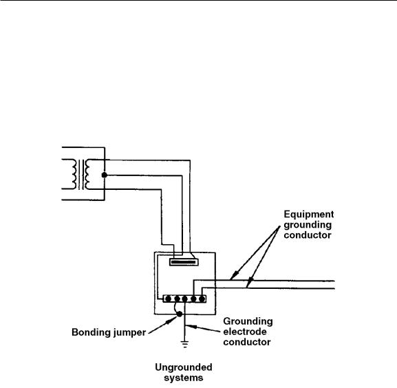
phases and ground are subjected to 1.732 times the voltage they would experience on a solidly neutral grounded system. (See Figure 4-3.)
Note: All ungrounded systems should be equipped with ground detectors and proper maintenance applied to avoid, as far as practical, the overcurrent of a sustained ground fault on ungrounded systems. If appropriate maintenance is not provided for ungrounded systems, a grounded system should be installed to ensure that ground faults will be cleared and the safety of circuits, equipment, and that personnel safety is ensured.
NEC Section 250-5 (b) Ex. 1-5
OSHA Section 29 CFR 1910.304 (f)
Figure 4-3. An ungrounded system does not have a grounded (neutral) conductor routed between the supply transformer and the service equipment because the supply transformer is not earth grounded.
4.5.3 HIGH-IMPEDANCE GROUNDING
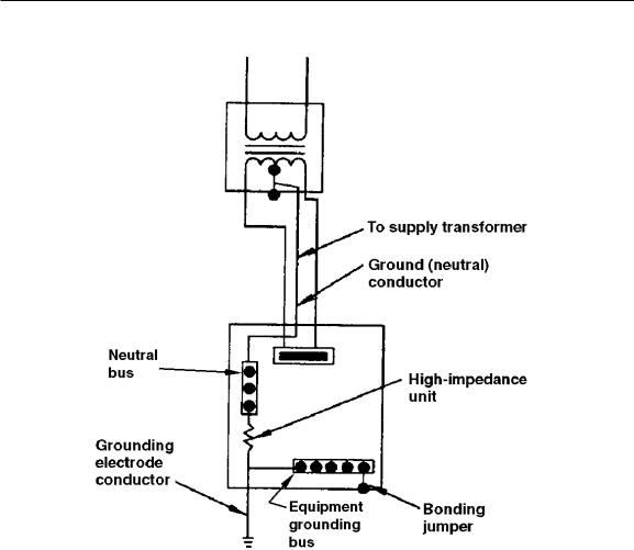
Electrical systems containing three-phase, three-wire loads, as compared to grounded neutral circuit conductor loads, can be equipped with a high-impedance grounded system. High-impedance grounded systems shall not be used unless they are provided with ground fault indicators or alarms, or both, and qualified personnel are available to quickly locate and eliminate such ground faults. Ground faults must be promptly removed or the service reliability will be reduced. See NEC Section 250-27 for requirements pertaining to installing a high-impedance grounding system. (See Figure 4-4.)
4-6
DOE-HDBK-1092-98
NEC Section 250-27
Figure 4-4. A high-impedance grounding system has a high-impedance unit, installed between the grounded (neutral) conductor and the grounding electrode conductor, which is used to regulate fault current.
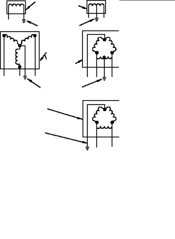
4.6 GROUNDING REQUIREMENTS
Alternating current systems of less than 50 volts shall be grounded as required in NEC Section 250- 5(a). Systems of 50 to 1,000 V should be solidly grounded as required by NEC Section 250-5. Systems supplying phase-to-neutral loads shall also be solidly grounded (See Figure 4-5). The following electrical systems are required to be solidly grounded:
1.120/240-V, single-phase, three-wire
2.208Y/120-V, three-phase, four-wire,
3.480Y/277-V, three-phase, four-wire,
4-7
DOE-HDBK-1092-98
4.120/240-V, three-phase, four-wire, delta. (Midpoint of one phase used as a grounded circuit conductor.)
The following systems are not required to be solidly grounded:
1.240-V, three-phase, three-wire, delta
2.480-V, three-phase, three-wire
3.600-V, three-phase, three-wire.
These electrical systems do not supply phase to neutral loads. They supply only phase-to-phase
loads.
Transformer secondary
1φ, Wire
120 V 1φ, 3 Wire 120/240 V
(Neutral) Grounded conductor
Transformer secondary
3φ, 4 W
120/208 V 277/480 V
120/240 V and
1φ, 208 V
(Neutral) Grounded conductor
Transformer secondary corner ground
3φ, 3 W
240 V
480 V
Grounded conductor (Not a neutral)
NEC Section 250-5 (b)
OSHA Section 29 CFR 1910.304 (f) (1) (iv)
Figure 4-5. Systems of 50 to 1,000 V AC that operate grounded are required to have the grounded conductor connected to earth ground at the supplying transformer and service equipment.
4-8
DOE-HDBK-1092-98
4.7 GROUNDING ELECTRODE CONDUCTOR (GEC)
The main purpose of the grounding electrode conductor (GEC) is to connect the electrical system to earth ground. The GEC actually provides three grounding paths to the grounding electrode system. They are as follows:
1.The grounded conductor path
2.The equipment grounding path
3.The bonding path.
In grounded systems, the GEC connects to the neutral bar in the service equipment enclosure. In ungrounded systems, the GEC connects to the grounding terminal bar. It grounds the following items to the grounding electrode system:
1.The grounded conductor, if present
2.The equipment grounding conductor, if present
3.The metal of conduits, if present
4.The metal of enclosures, if present
5.The bonding jumpers bonding together metal enclosures and conduits
6.The metal enclosure of the service equipment.
4.7.1SIZING THE GROUNDING ELECTRODE CONDUCTOR
NEC Section 250-94 requires the grounding electrode conductor to be sized by the circular mils rating of the largest service entrance conductor or conductors and selected from NEC Table 250-94 based on these values.
For example, the size of the service entrance conductors from a delta, three-phase, four-wire midpoint tap is #250 kcmil, THWN copper for phases A and C, #2/0 for phase B, and #1/0 for the neutral. What size copper GEC is required to ground this system to a metal water pipe?
Step 1: Finding the largest phase—NEC 250-94 #250 kcmil is the largest phase
Step 2: Finding the size GEC—NEC Table 250-94 #250 kcmil requires # 2 cu
Answer: The size of grounding electrode conductor (GEC) is at least #2 copper.
Note: NEC Table 250-94 is used to size the grounding electrode conductor for both grounded and ungrounded systems. The table is used where the grounding electrode conductor is connected to a metal water pipe or the metal frame of building steel.
4-9

DOE-HDBK-1092-98
4.7.2 EXCEPTIONS TO NEC 250-94
There is an exception to the main rule. It has three parts and pertains to specific types of grounding electrodes. The exception applies to grounded and ungrounded systems.
Exception (a) applies to made electrodes only, such as rod, pipe, or plate electrodes. The grounding electrode conductor is not required to be larger than #6 copper or #4 aluminum.
Exception (b) to NEC Section 250-94 requires at least a #4 copper conductor to be used as a grounding electrode conductor to ground the electrical system to a concrete-encased electrode.
Exception (c) requires at least a #2 copper conductor to be used as a grounding electrode conductor to ground the electrical system to a ground ring. [See NEC Section 250-81(d)]
4.8 MAIN BONDING JUMPER
The primary function of the main bonding jumper is to connect the grounded circuit conductors and the equipment grounding conductors at the service equipment. The main bonding jumper serves as the main link between the system grounded conductors and the grounding electrode system where metal equipment enclosures and raceways are utilized to enclose conductors and components. If the main bonding jumper is left out, there is not a complete circuit for fault current and is an invitation to a dangerous situation.
The main bonding jumper shall connect together the following items:
1.Grounded conductors and grounded terminal
2.Equipment grounding conductors and grounding terminal
3.All metal enclosures enclosing conductors and components.
If supplied, the manufacturers main bonding jumper is the preferred conductor to be used as the main bonding jumper. NEC Section 250-79(a) requires the main bonding jumper to be a (1) wire, (2) screw, (3) busbar, or (4) a similar suitable conductor.
NEC Section 250-79(d) requires the main bonding jumper to be at least the same size as the grounding electrode conductor where the circular mils rating of the service entrance conductors does not exceed 1100 kcmil for copper or 1750 kcmil for aluminum.
For example: What size main bonding jumper is required to ground the metal enclosure of the service equipment to the grounding terminal bar where the service entrance is made up of one #250 kcmil, THWN copper conductor per phase?
4-10

DOE-HDBK-1092-98
Step 1: Finding the largest phase—NEC 250-79(d) #250 kcmil is the largest phase
Step 2: Finding the bonding jumper—Table 250-94 #250 kcmil requires #2 copper
Answer: The size of the main bonding jumper (GEC) is at least #2 copper.
Where the kcmil rating of the service entrance conductors exceeds 1100 kcmil for copper or 1750 for aluminum, the bonding jumper shall be at least 12 l/2% of the largest kcmil rating of any one phase.
For example: What size main copper bonding jumper is required for a service entrance with a makeup of 2400 kcmil copper conductors per phase?
Step 1: Finding the largest phase—NEC 250-79(d) 2400 kcmil x 0.125 = 300 kcmil
Step 2: Finding the main bonding jumper—NEC Table 250-94; Table 8, Ch. 9 requires 300 kcmil
Answer: The main bonding jumper is required to be at least 300 kcmil copper.
Note: In this case the main bonding jumper is greater in size than the grounding electrode conductor, which is only required to be #3/0 copper per NEC Table 250-94 based upon the 2400 kcmil copper conductors.
4.9 SYSTEM WITH GROUNDED CONDUCTOR
The main purpose of the grounded conductor is to carry unbalanced neutral current or fault current in the event that one phase should go to ground.
Note: The grounded conductor does not always have to be a neutral conductor. It is a phase conductor when used in a corner grounded delta system.
In solidly grounded service-supplied systems, the equipment grounding conductors shall be bonded to the system-grounded conductor and the grounding electrode conductor at the service equipment. The grounded conductor may be used to ground the noncurrent-carrying metal parts of equipment on the supply side of the service disconnecting means per NEC Section 250-61(a). The grounded conductor can also serve as the ground-fault current return path from the service equipment to the transformer that supplies the service.
The grounded conductor shall not be used to ground the metal parts of enclosures enclosing conductors and components on the load side of the service per NEC Section 250-61(b). See NEC
4-11

DOE-HDBK-1092-98
Sections 250-50(a), (b), Ex. and 250-60 for exceptions to this basic rule. NEC Section 250-23(a) requires the grounded conductor to be connected as follows:
1.The grounded conductor shall be connected to the grounded (neutral) service conductor.
2.The connection shall be at an accessible point.
3.That accessible point can be anywhere from the load end of the service drop or service lateral to and including the neutral bar in the service disconnecting means or service switchboard.
The NEC allows the grounded conductor to be terminated and connected to ground at a multitude of locations on the supply side of the service equipment. These locations are as follows:
1.Service equipment
2.Meter base
3.Current transformer (CT) can
4.Metal gutter or wireway containing service entrance conductors.
See Figure 4-6 for the rules concerning the use of the grounded conductor.
NEC Section 250-23(b) lists the rules for sizing the grounded conductor where it is not used as a grounded neutral circuit. NEC Section 220-22 gives the rules for calculating and sizing the grounded conductor when it is used as a circuit conductor. The minimum size for the grounded conductor is computed as follows:
1.The basic rule is to select the size directly from Table 250-94 when the size of the serviceentrance conductors is not larger than 1100 kcmil copper or 1750 kcmil aluminum.
2.When the service entrance conductors are larger than 1100 kcmil copper or 1750 kcmil aluminum, the grounded conductor shall be 12 1/2% of the largest phase conductor.
3.Where the service phase conductors are paralleled, the size of the grounded conductor shall be based on the total cross-sectional area of the phase conductors.
For example: What size THWN copper grounded conductor is required for a service having a total kcmil rating of 250 per phase? (All phase conductors are THWN copper.)
Step 1: Service less than 1100 kcmil—NEC Table 250-94 250 kcmil requires #2 copper
Answer: The size of the grounded conductor is at least #2 THWN copper.
For example: What size THWN copper grounded conductor is required for a parallel service having a total kcmil rating of 2400 per phase? (All conductors are THWN copper.)
4-12
DOE-HDBK-1092-98
NEC Section 250-23 (b)
OSHA Section 29 CFR 1910.304 (f) (4)
Figure 4-6. The grounded (neutral) conductor is used to carry normal neutral current or ground fault current in case a ground fault should develop on one of the ungrounded (hot) phase conductors.
Step 1: |
Service exceeding 1100 kcmil—NEC Table 250-94 2400 kcmil x 0.12 5 = 300 |
|
kcmil |
Answer: |
The grounded conductor is required to be at least a #300 kcmil, THWN copper |
|
conductor. |
|
|
This method is used where the service entrance conductors are over 1100-kcmil copper or 1750-kcmil aluminum. NEC Table 250-94 cannot be used for sizing the grounded conductor. The grounded conductor is required to be not less than 12 1/2% of the cross-sectional area of the largest phase conductor.
Note: NEC Table 250-94 is used only if the service conductors are rated less than 1100 kcmil for copper or 1750 kcmil for aluminum.
4-13

DOE-HDBK-1092-98
4.10 EQUIPMENT GROUNDING CONDUCTOR
Equipment grounding conductors for ac systems, where used, should be run with the conductors of each circuit per NEC Section 250-57(b).
Earth and the structural metal frame of a building may be used for supplemental equipment bonding, but they shall not be used as the sole equipment grounding conductor for ac systems per NEC Sections 250-58 and 250-51.
For circuits having paralleled conductors in multiple metal raceways, an equipment grounding conductor shall be run in each raceway. The size of each paralleled equipment grounding conductor is a function of the rating of the circuit overcurrent protection. (See NEC Sections 250-95 and 310-4.)
4.10.1 SIZING THE EQUIPMENT GROUNDING CONDUCTOR
NEC Section 250-95 lists the requirements for calculating the size of the equipment grounding conductors in an electrical circuit. There are basically five steps to be applied in sizing, selecting, and routing the equipment grounding conductors:
1.NEC Table 250-95 shall be used to size the equipment grounding conductor.
2.When conductors are run in parallel in more than one raceway, the equipment grounding conductor is also run in parallel.
3.Where more than one circuit is installed in a single raceway, one equipment grounding conductor may be installed in the raceway. However, it must be sized for the largest overcurrent device protecting conductors in the raceway.
4.When conductors are adjusted in size to compensate for voltage drop, the equipment grounding conductor shall also be adjusted in size.
5.The equipment grounding conductor is never required to be larger than the circuit conductors.
For example: What size THWN copper equipment grounding conductor is required to be run in a raceway with a 70 A overcurrent protection device protecting the circuit?
Step 1: Finding EGC—NEC Table
250-95 70 A OCPD requires #8 copper
Answer: The equipment grounding conductor is required to be at least #8 THWN copper.
4-14

DOE-HDBK-1092-98
4.10.2 SEPERATE EQUIPMENT GROUNDING CONDUCTORS
The possibility of worker exposure to electric shock can be reduced by the use of seperate equipment grounding conductors within raceways.
The seperate equipment grounding conductors contribute to equalizing the potential between exposed noncurrent-carrying metal parts of the electrical system and adjacent grounded building steel when ground faults occur. The resistance (inductive reactance) of the ground fault circuit normally prevents a significant amount of ground fault current from flowing through the seperate equipment grounding conductors.
Ground fault current flows through the path that provides the lowest ground fault circuit impedance. Fittings and raceway systems have been found that are not tightly connected or are corroded which prevents good continuity. Therefore, the equipment grounding conductor shall be the path for the fault current to travel over and clear the overcurrent protection device protecting the circuit.
NEC Sections 300-3(b) and 250-57(b) require the equipment grounding conductors to be routed in the same raceway, cable, cord, etc., as the circuit conductors. All raceway systems should be supplemented with seperate equipment grounding conductors.
Note: The equipment grounding conductor shall be routed with supply conductors back to the source. Additional equipment grounding may be made to nearby grounded structural members or to grounding grids, but this shall not take the place of the co-routed equipment grounding conductors. Raceway systems should not be used as the grounding conductor.
4.11 UNGROUNDED SYSTEMS
Three-phase, three-wire, ungrounded systems (DELTA), which are extensively used in industrial establishments, do not require the use of grounded conductors as circuit conductors.
The same network of equipment grounding conductors shall be provided for ungrounded systems as for grounded systems. Equipment grounding conductors are required in ungrounded systems to provide shock protection and to present a low-impedance path for phase-to-phase fault currents in case the first ground fault is not located and cleared before another ground fault occurs on a different phase in the system.
Grounding electrode conductors and bonding jumpers shall be computed, sized, and installed in the same manner as if the system were a grounded system. Apply all the requirements listed in Sections 4.6 through 4.8 for sizing the elements of an ungrounded system.
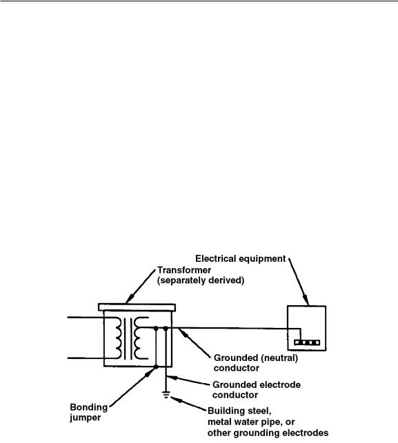
4.12 GROUNDING A SEPARATELY DERIVED SYSTEM
NEC Sections 250-5(d) and 250-26 cover the rules for grounding separately derived systems. The system grounding conductor for a separately derived system shall be grounded at only one point. That single system grounding point is at the source of the separately derived system and ahead of any
4-15
DOE-HDBK-1092-98
system disconnecting means or overcurrent devices. Where the main system disconnecting means is adjacent to the generator, converter, or transformer supplying a separately derived system, the grounding connection to the system grounded conductor can be made at or ahead of the system disconnecting means.
The preferred grounding electrode for a separately derived system is the nearest effectively grounded structural metal member of the building or the nearest effectively grounded water pipe. If neither is available, concrete-encased electrodes or made electrodes are permitted.
In a grounded, separately derived system, the equipment grounding conductors shall be bonded to the system-grounded conductor and to the grounding electrode at or ahead of the main system disconnecting means or overcurrent protection device. The equipment grounding conductor should always be connected to the enclosure of the supply transformer, generator, or converter.
The grounding electrode conductor, the main bonding jumper, the grounded conductor, and the equipment grounding conductor are calculated, sized, and selected by the rules listed in Sections 4.7 through 4.10. (See Figure 4-7.)
NEC Section 25026
OSHA Section 29 CFR 1910.304 (f) (3) (ii)
Figure 4-7. The grounded (neutral) conductor can be used to carry both normal neutral current and abnormal ground fault current.
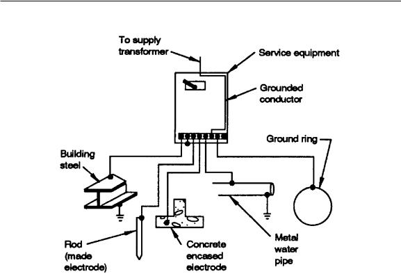
4.13 GROUNDING ELECTRODE SYSTEM
If 10 ft or more of metal water pipe is in the earth, the water pipe is considered the grounding electrode, but it shall be supplemented by an additional electrode. NEC Section 250-81 lists four types of electrodes. If one or all are available, they shall be bonded together to make up the grounding electrode system. The bonding jumper that connects these electrodes shall be at least as large as the
4-16

DOE-HDBK-1092-98
grounding electrode conductor of the system sized by NEC Table 250-94. The four types of electrodes are as follows:
1.Metal water pipe in contact with the earth for 10 ft. or more. Interior metal water pipe beyond 5 ft. from the water entrance shall not be used as a part of the grounding electrode system or as a conductor to interconnect those electrodes. (See NEC Section 250-81.)
2.Metal frame of the building, where effectively grounded
3.Bare #4 conductor at least 20 ft in length and near the bottom of the concrete foundation (within 2 in.), or 1/2 in. reinforcing steel or rods at least 20 ft in length (one continuous length or spliced together)
4.Bare #2 conductor encircling building at least 2-1/2 ft. in the ground (spliced together at each end).
The grounding electrode conductor at the service equipment can be connected to any convenient interbonded electrodes that provide a solid, effective connection. Metal water pipe shall be supplemented by an additional electrode, which can be any of the following electrodes:
1.A rod
2.Pipe
3.Plate
4.Building steel
5.Concrete-encased electrode.
(See Figure 4-8, which lists some of the different types of grounding electrodes.)
4.14 GROUND-FAULT PROTECTION OF EQUIPMENT
See Section 2.7 for ground fault circuit interrupters for personnel protection. An increased degree of protection in solidly grounded systems can be achieved in providing ground-fault protection that will shunt trip circuit protective devices when user-selected levels of ground fault or leakage current flow are detected in electrical circuits. This is required to be installed on all solidly grounded wye services of more than 150 V to ground but not exceeding 600 V phase-to-phase where the service disconnecting means is rated at 1,000 A or more (See NEC Sections 215-10, 230-95, 240-13, and Figure 3-1).
4.15 PERSONNEL PROTECTIVE GROUNDS
Personnel working on or close to deenergized lines or conductors in electrical equipment should be protected against shock hazard and flash burns that could occur if the circuit were inadvertently reenergized. Properly installed equipotential protective grounds can aid in lessening such hazards by providing additional protection to personnel while they service, repair, and work on such systems.(See Section 7.5).
4-17
DOE-HDBK-1092-98
NEC Section 25081
OSHA Section 29 CFR 1910.304 (f)
Figure 4-8. If the building steel, metal water pipe, concrete-encased electrode, and ground ring are available, they must be grounded and bonded to the service equipment to create the grounding electrode system.
4.15.1 PURPOSE OF PERSONNEL PROTECTIVE GROUNDS
Personnel protective grounds are applied to deenergized circuits to provide a low-impedance path to ground should the circuits become reenergized while personnel are working on or close to the circuit. In addition, the personnel protective grounds provide a means of draining off static and induced voltage from other sources while work is being performed on a circuit. (Figure 4-9 illustrates an example of a personnel protective ground.)
4.15.2 CRITERIA FOR PERSONNEL PROTECTIVE GROUNDS
Before personnel protective grounds are selected, the following criteria shall be met for their use, size, and application.
1.A grounding cable shall have a minimum conductance equal to #2 AWG copper.
2.Grounding cables shall be sized large enough to carry fault current long enough for the protective devices to sense and the circuit breaker to clear the fault without damage to cable insulation. An example would be a 4/0 Neoprene-insulated welding cable that will pass 30,000 A for 0.5 sec without melting its insulation.
4-18
DOE-HDBK-1092-98
OSHA Sects. 29 CFR 1910.269(n) and 1926.954(t)
Figure 4-9. Equipotential personnel protective grounds are used to protect electrical workers while they service, repair, or are close to circuits that can be accidentally reenergized.
3.The following are factors that contribute to adequate capacity:
a.Terminal strength depends on the ferrules installed on the cable ends
b.Cross-sectional area to carry maximum current without melting
c.Low resistance to keep voltage drop across the areas in which personnel are working at a safe level during any period to prevent reenergization. The voltage drop should not exceed 100 volts for 15 cycle or 75 volts for 30 cycle clearing times.
d.Verify that the grounding cable and clamp assembly is tested periodically by using the millivolt drop, micro-ohm meter, AC resistance, or DC resistance test methods. For example, if it is desired to maintain a maximum of 100 volts across a worker whose body resistance is 1000 ohms, during a fault of 1000 amperes, a personnel protective ground resistance of 10 millohms or less is required.
4.For further information on the construction of personnel protective grounds, refer to ASTM F855-90, IEEE 524A, IEEE 1048, and Section 7.5.
4.15.3 GROUNDING CLAMPS
Grounding clamps used in personnel protective grounds are manufactured specifically for this use. The size of grounding clamps shall match the size of conductor or switchgear bus being grounded.
4-19

DOE-HDBK-1092-98
The ground clamp also shall be rated to handle the full capacity of the available fault currents. Fault currents can typically range in magnitude up to over 200,000 A.
4.15.4 SCREW-TIGHTENING DEVICES
Approved screw-tightening devices designed for the purpose of pressure metal-to-metal contact are required for connections to an adequate system ground.
4.15.5 GROUNDING CABLE LENGTH
Grounding cables should be no longer than is necessary, both to minimize voltage drop and to prevent violent movement under fault conditions. For example, as a general rule, grounding cables should not exceed 30 ft for a transmission line and 40 ft for substation use.
4.15.6 GROUNDING CABLE CONNECTION
Grounding cables shall be connected between phases to the grounded structure and to the system neutral to minimize the voltage drop across the work area if the circuit should become inadvertently reenergized. Workers shall install the ground end clamp of a grounding cable first and remove it last.
4.15.7 CONNECTING GROUNDING CABLES IN SEQUENCE
Grounding cables shall be connected to the ground bus, structure, or conductor first, then to the individual phase conductors. The first connection of the grounding cables to the circuit phase conductors shall be to the closest phase of the system and then to each succeeding phase in the order of closeness.
4.15.8 REMOVING PROTECTIVE GROUNDS
When removing personnel protective grounds, reverse the order they were applied to the phases. The grounding cable conductors attached to the ground bus, structure, or conductors shall always be removed last.
4.15.9 PROTECTIVE APPAREL AND EQUIPMENT
Protective apparel shall be worn when applying or removing grounds. An insulating tool (hot stick) shall be used to install and remove grounding cables. (See 29 CFR 1910.269(n)(6) and (7), 1926.954(e) and NESC Rule 445).
Protective apparel (personnel protective equipment) should include at least the following:
1.Safety glasses and, if necessary, face shield appropriate for fault currents available.
2.Hardhat (Class B) (See 2.12.3)
3.Appropriate electrical gloves and protectors (See 2.12.3).
4.Appropriate clothing (See note in 2.11.3).
4-20

DOE-HDBK-1092-98
CONTENTS
5.0 SPECIAL OCCUPANCIES .................................................................................. |
|
5-1 |
||
5.1 EXPLOSIVES ............................................................................................. |
|
|
5-1 |
|
5.1.1 |
EVACUATION ............................................................................... |
|
5-1 |
|
5.1.2 |
SHUTDOWN OF OPERATIONS ................................................... |
5-1 |
||
5.1.3 |
LIGHTNING PROTECTION .......................................................... |
5-1 |
||
5.1.4 |
STATIC ELECTRICITY ................................................................. |
5-2 |
||
|
5.1.4.1 |
BONDING AND GROUNDING EQUIPMENT .............. |
5-2 |
|
|
5.1.4.2 TESTING EQUIPMENT GROUNDING SYSTEMS ....... |
5-2 |
||
|
5.1.4.3 CONDUCTIVE FLOORS, SHOES, MATS, |
|
||
|
|
AND WRISTBANDS ...................................................... |
5-3 |
|
|
5.1.4.4 |
SPECIFICATIONS FOR CONDUCTIVE FLOORS |
|
|
|
|
AND WRISTBANDS ...................................................... |
5-3 |
|
|
5.1.4.5 |
CONDUCTIVE FLOOR TEST ....................................... |
5-4 |
|
|
5.1.4.6 |
HUMIDIFICATION ......................................................... |
5-4 |
|
|
5.1.4.7 |
GROUND-FAULT CIRCUIT INTERRUPTER ................ |
5-4 |
|
5.1.5 ELECTRICAL EQUIPMENT AND WIRING .................................. |
5-4 |
|||
|
5.1.5.1 PERMANENT EQUIPMENT AND WIRING ................... |
5-5 |
||
|
5.1.5.2 |
HAZARDOUS LOCATIONS .......................................... |
5-5 |
|
|
5.1.5.3 |
ELECTRICAL SUPPLY SYSTEMS ............................... |
5-6 |
|
|
5.1.5.4 |
BUILDING SERVICE ENTRANCE ................................ |
5-7 |
|
5.1.6 |
TESTING |
....................................................................................... |
|
5-8 |
|
5.1.6.1 |
TEST SETUP ................................................................. |
5-8 |
|
|
5.1.6.2 PIN SWITCHES AND OTHER NONINITIATING |
|
||
|
|
CIRCUITS ...................................................................... |
|
5-8 |
|
5.1.6.3 |
LIGHTNING STORMS ................................................... |
5-8 |
|
|
5.1.6.4 |
LOW-ENERGY ELECTROEXPLOSIVE DEVICES ....... |
5-8 |
|
|
5.1.6.5 |
WARNING SIGNALS .................................................. |
5-10 |
|
|
5.1.6.6 |
FIRING LEADS ............................................................ |
5-11 |
|
|
5.1.6.7 |
ELECTRICAL TESTING INSTRUMENTS FOR USE |
|
|
|
|
WITH EXPLOSIVES SYSTEMS (EXCEPT THOSE |
|
|
|
|
COVERED BY DOE 5610.3) ....................................... |
5-11 |
|
|
|
5.1.6.7.1 |
CLASSIFICATION .................................... |
5-11 |
|
|
5.1.6.7.2 |
CERTIFICATION ....................................... |
5-11 |
|
|
5.1.6.7.3 |
ELECTRICAL TESTING INSTRUMENTS |
|
|
|
|
FOR USE WITH INITIATING |
|
|
|
|
ELECTRICAL CIRCUITS .......................... |
5-12 |
|
|
5.1.6.7.4 |
ELECTRICAL TESTING INSTRUMENTS |
|
|
|
|
FOR USE WITH NONINITIATING |
|
|
|
|
ELECTRICAL CIRCUITS .......................... |
5-12 |
5.2 PREVENTION OF EXTERNAL IGNITION AND EXPLOSION ............... |
5-12 |
|||
5.2.1 |
SOURCES OF IGNITION ............................................................ |
5-13 |
||
5.2.2 |
COMBUSTION PRINCIPLES ..................................................... |
5-14 |
||
|
|
|
5-1i |
|

DOE-HDBK-1092-98
|
5.2.3 EVALUATION OF HAZARDOUS AREAS ................................. |
5-14 |
||
|
5.2.4 |
INTRINSICALLY SAFE EQUIPMENT ........................................ |
5-14 |
|
|
5.2.5 |
ENCLOSURES ............................................................................ |
5-15 |
|
|
5.2.6 |
PURGING/PRESSURIZATION SYSTEMS ................................. |
5-16 |
|
5.3 |
HAZARDOUS LOCATIONS .................................................................... |
5-17 |
||
|
5.3.1 |
CLASS I ...................................................................................... |
|
5-19 |
|
|
5.3.1.1 |
DIVISION 1 .................................................................. |
5-19 |
|
|
5.3.1.2 |
DIVISION 2 .................................................................. |
5-19 |
|
5.3.2 |
CLASS II |
..................................................................................... |
5-22 |
|
|
5.3.2.1 CLASS II DIVISION 1 .................................................... |
5-22 |
|
|
|
5.3.2.2 CLASS II DIVISION 2 .................................................... |
5-22 |
|
|
5.3.3 |
GROUPS |
..................................................................................... |
5-24 |
|
5.3.4 |
IGNITION TEMPERATURE ........................................................ |
5-24 |
|
|
5.3.5 |
FLAMMABLE (EXPLOSION) LIMITS ........................................ |
5-24 |
|
|
5.3.6 |
FLASHPOINT .............................................................................. |
5-25 |
|
5.4 ELECTRICAL EQUIPMENT FOR CLASS I, II, AND III AREAS ............. |
5-25 |
|||
|
5.4.1 |
SEALS AND DRAINS ................................................................. |
5-25 |
|
|
|
5.4.1.1 |
SEALS ......................................................................... |
5-25 |
|
|
5.4.1.2 |
DRAINS ....................................................................... |
5-26 |
|
|
5.4.1.3 SELECTION OF SEALS AND DRAINS ...................... |
5-26 |
|
|
|
|
5.4.1.3.1 PRIMARY CONSIDERATIONS ................ |
5-27 |
|
|
|
5.4.1.3.2 TYPES OF SEALING FITTINGS .............. |
5-27 |
5.5 |
MANUFACTURERS’ DIGEST ................................................................. |
5-28 |
||
5.6DESCRIPTIONS, FEATURES, AND TEST CRITERIA OF
|
ENCLOSURES FOR HAZARDOUS (CLASSIFIED) |
|
|
|
LOCATIONS (PER NEMA 250) ............................................................... |
5-28 |
|
5.7 |
TYPE 7 ENCLOSURES ........................................................................... |
5-28 |
|
|
5.7.1 |
DESCRIPTION AND APPLICATION .......................................... |
5-29 |
|
5.7.2 |
FEATURES AND TEST CRITERIA ............................................ |
5-29 |
5.8 |
TYPE 8 ENCLOSURES ........................................................................... |
5-29 |
|
|
5.8.1 |
DESCRIPTION AND APPLICATION .......................................... |
5-29 |
|
5.8.2 |
FEATURES AND TEST CRITERIA ............................................ |
5-30 |
5.9 |
TYPE 9 ENCLOSURES ........................................................................... |
5-30 |
|
|
5.9.1 |
DESCRIPTION AND APPLICATION .......................................... |
5-30 |
|
5.9.2 |
FEATURES AND TEST CRITERIA ............................................ |
5-30 |
5.10 |
UNDERGROUND FACILITIES ................................................................ |
5-31 |
|
|
5.10.1 |
WORK ON ELECTRICAL EQUIPMENT AND CIRCUITS .......... |
5-32 |
|
5.10.2 |
GROUNDING .............................................................................. |
5-32 |
|
5.10.3 |
POWER CABLES AND CONDUCTORS ................................... |
5-33 |
5--2ii

DOE-HDBK-1092-98
5.10.4 |
TRAILING CABLES .................................................................... |
5-33 |
5.10.5 |
TROLLEY CIRCUITS FOR TRACK HAULAGE ......................... |
5-34 |
5-iii3

DOE-HDBK-1092-98
This page left blank intentionally.
5-iv4