


DOE-HDBK-1092-98
3.0 ELECTRICAL PREVENTIVE MAINTENANCE
The term “electrical preventive maintenance” (EPM) refers to a program of regular inspection and service of equipment to detect potential problems and to take proper corrective measures.
3.1 DEVELOPMENT AND IMPLEMENTATION REQUIREMENTS
An EPM program should be developed and implemented based on the requirements of:
1.DOE 4330.4B, Maintenance Management Program
2.NFPA 70B, Recommended Practice for Electrical Equipment Maintenance
3.NFPA 70E, Standard for Electrical Safety Requirements for Employee Workplaces
4.NFPA 72, National Fire Alarm Code
5.National Electrical Testing Association (NETA).
6.ANSI-C2, National Electrical Safety Code
3.2DEFINITION
An EPM program is defined as the system that manages the conducting of routine inspections and tests and the servicing of electrical equipment so that impending troubles can be detected and reduced or eliminated. Where designers, installers, or constructors specify, install, and construct equipment with optional auxiliary equipment, that optional equipment should be part of the EPM program. Records of all inspections, tests, and servicing should be documented and reviewed.
All electrical equipment that is appropriate for EPM should be inspected, tested, and serviced in accordance with an EPM program.
Inspections, tests, and servicing shall be performed by personnel who are qualified for the work to be performed. These qualifications can be shown by appropriate documentation of work experience, on-the-job, and offsite formal training to verify understanding and retention of minimum knowledge, skills, and abilities.
3.3 MAINTENANCE
Electrical equipment should be maintained in accordance with the manufacturer’s recommendations and instructions for the local operating environment. A copy of the manufacturer’s recommendation should be documented and on file.
3-1

DOE-HDBK-1092-98
3.4 INSPECTION
If an EPM program does not exist, an inspection, testing, and servicing program should be developed and implemented to establish a baseline to initiate an EPM program. The inspection frequency should be as recommended by the manufacturer or as otherwise indicated in NFPA 70B. An initial period of inspection (sometimes several years) provides sufficient knowledge, which when accumulated, might permit increasing or decreasing that interval based upon documented observations and experience.
One guidance on how to determine inspection frequency is described in various sections of NFPA 70B, including but not limited to the following sections:
1.4-4.5; Inspection Frequency for Planning and Developing an Electrical Preventive Maintenance Program
2.6-1.1.3; Recommended Frequency for Substations
3.6-2.2; Frequency of Maintenance for Switchgear Assemblies
4.7-2.2; Regular Inspections and 7-2.7; Special Inspections and Repairs for Liquid-Filled Transformers
5.7.3.2; Regular Inspections and 7-3.7; Special Inspections and Repairs for Dry-Type Transformers
6.8-2.6; Visual Inspection Intervals for Power Cables
7.9-2; Frequency of Inspections for Enclosures of Motor Control Centers
8.12-2.2.3; Recommended Frequency for Ground-Fault Circuit Interrupters
9.13-2.1; General and 13-2.3; Inspection and Cleaning for High-Voltage Fuses
10.14-1.2; Frequency for Rotating Equipment
11.15-2.1; Cleaning Interval for Lighting Equipment
12.17-1.3; Visual Inspection Before and After Each Use, 17-3.1; Periodic Inspection of Crucial Wear Points, 17-3.2; Excessive Dirt Accumulation, 17-3.3; Insufficient or Improper Lubrication, and 17-4.2; Visually Inspected Before Each Use for Portable Electric Tools and Equipment
13.18-2.3; Special Maintenance Tests, 18-4; Frequency of Tests, 18-16.5; Inspection Frequency and Procedures, and 18-18; Insulating-Liquid Analysis for Testing and Test Methods
3-2

DOE-HDBK-1092-98
14.19-2.1.1(e); Reinspection and Retesting Within One or Two Years After Energization for General Aspects of Maintaining Mediumand Low-Voltage Distribution Systems, 19-3.7.; Frequency, 19-3.7.3; Regreasing, and 19-3.7.8; Frequency for Lubrication of Rotating Equipment
15.19-3.13.4; Inspections Should Be Made of All New Installations and Whenever Alterations Are Made and 19-3.13.6; Recordkeeping for Electrostatics Static Grounding (see NFPA 77)
16.19-4.3.4; Inspection and Testing of Power Supplies, 19-4.4.2; Functional Systems Testing of Interlock and Logic Systems, 19-4.6.2; Visual Inspection of Level Devices, 19-4.10.1; Frequency of Testing Safety and Shutdown Systems, 19-4.11.1; Frequency of Testing Alarm Systems, and 19-4.12.1; Visual Checking of Wiring Systems for Process Instrumentation and Control
17.21-1.2; Frequency for Cable Tray System
18.22-2.1.8; Routine Maintenance for Uninterruptible Power Supply (UPS) Systems
3.5ESSENTIAL ELEMENTS
The EPM program should include the essential elements described in NFPA 70B, Chapter 3, “What is an Effective EPM Program.” This includes planning, identifying the main parts, and utilizing available support services for a program. For example:
1.Assigning qualified personnel
2.Surveying and analyzing equipment maintenance requirements
3.Performing routine inspections and tests
4.Analyzing inspection and test reports
5.Prescribing corrective measures
6.Performing necessary work
7.Preparing appropriate records.
3.6PLANNING AND DEVELOPING AN EPM PROGRAM, AND FUNDAMENTALS OF EPM
The EPM program should be planned and developed to include each of the functions, requirements, and economic considerations described in NFPA 70B, Chapter 4, “Planning and Developing an EPM Program,” and NFPA 70B, Chapter 5, “Fundamentals of EPM.” Chapter 4 includes surveying the existing electrical system installation, identifying crucial equipment, establishing a systematic
3-3

DOE-HDBK-1092-98
program to follow, and developing methods and procedures to plan, analyze, perform, verify, and record.
Electrical drawings should be kept current. A system of recording changes in electrical systems and then integrating those changes into the applicable drawings should be developed and implemented.
NFPA 70B, Chapter 5, includes designing to accommodate maintenance, scheduling maintenance, personnel and equipment safety, circuit protection, and initial acceptance testing.
3.7 GROUND-FAULT PROTECTION
The EPM program should include the essential ingredients of Chapter 12 of NFPA 70B, “GroundFault Protection.” This includes ground fault circuit interrupters (GFCIs) and ground-fault protection for equipment (GFPE).
Ground-fault protective devices are intended to protect personnel and equipment. There are two distinct types, GFCI and GFPE, and it is of extreme importance to understand the difference between them.
A GFCI is defined in Article 100 of the NEC as a device intended for the protection of personnel in their job assignments. (See NEC Sections 210-7(d), 210-8, 215-9, 305-6, 427-26 and Section 2.71.)
A GFPE is defined in Article 100 of the NEC as a system intended to provide protection of equipment from line-to-ground fault currents. GFPE systems (equipped with or without a test panel) shall be inspected and tested at installation and at specified intervals as recommended by the manufacturer. (See NEC Sections 215-10, 230-95, and 240-13 and Section 4.14.)
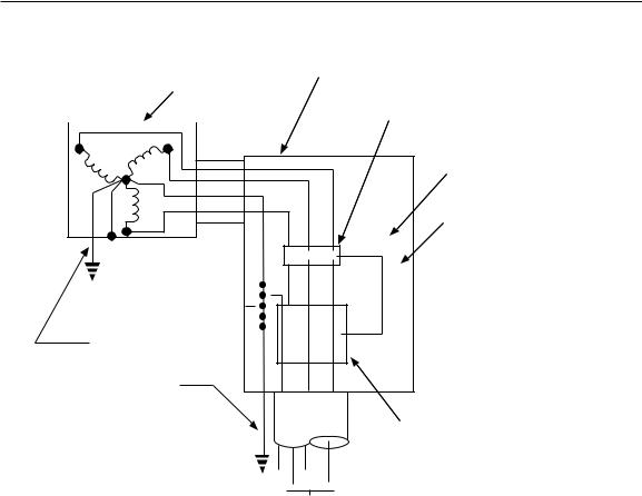
Figure 3-1 shows a zero sequence type of ground fault protection. See NEC Section 230-95 and 240-13 and NEMA PB2.2, “Application Guide for Ground Fault Protection Devices for Equipment.”
1 See Appendix D, Reference Matrix
3-4
DOE-HDBK-1092-98
Utility |
Service |
||
transformer |
|||
equipment |
|||
|
|
||
|
|
1000 A or more OCPD |
|
|
|
||
|
|
• NEC 230-95 |
|
Grounding electrode conductor
|
|
|
|
|
|
|
|
|
Shunt trip CB |
|
|
|
|
|
|
|
|
|
Relay |
|
|
|
|
|
|
|
|
|
0 to 1200 A setting |
|
|
|
|
|
|
|
|
R |
|
|
|
|
|
|
|
|
|
• NEC 230-95 (a) |
|
|
|
|
|
|
|
|
|
||
|
|
|
|
|
|
|
|
||
|
|
|
|
|
|
|
|
Clearing time |
|
|
|
|
|
|
|
|
|
|
|
|
|
|
|
|
|
|
|
|
|
|
|
|
|
|
|
|
|
|
|
|
|
|
|
|
|
|
|
|
shall clear a fault |
|
|
|
|
|
|
|
|
|
|
|
|
|
|
|
|
|
|
|
of 3000 A or more |
|
|
|
|
|
|
|
|
|
in 1 second |
|
|
|
|
|
|
|
|
|
|
Ground fault sensor
To load |
Z93 0403 |
NEC Section 230-95
Figure 3-1. Ground-fault protection shall be provided with 277/480-V, three-phase, four-wire services with overcurrent protection devices of 1,000 A or more. A ground fault sensor (window) can be used to encircle all service conductors, including the grounded conductor (neutral).
3-5

DOE-HDBK-1092-98
This page left blank intentionally.
3-6
DOE-HDBK-1092-98
CONTENTS
4.0 GROUNDING |
....................................................................................................... |
4-1 |
|
4.1 |
REGULATIONS, CODES, AND REFERENCES ....................................... |
4-1 |
|
|
4.1.1 ENGINEERING SPECIFICATIONS AND DRAWINGS ................ |
4-2 |
|
4.2 |
CIRCUIT AND SYSTEM GROUNDING ..................................................... |
4-2 |
|
4.3 |
EQUIPMENT GROUNDING ....................................................................... |
4-2 |
|
4.4 |
BONDING .................................................................................................. |
4-3 |
|
4.5 |
GROUNDED OR UNGROUNDED SYSTEMS .......................................... |
4-4 |
|
|
4.5.1 |
GROUNDED SYSTEMS ............................................................... |
4-4 |
|
4.5.2 |
UNGROUNDED SYSTEMS .......................................................... |
4-5 |
|
4.5.3 |
HIGH-IMPEDANCE GROUNDING ............................................... |
4-6 |
4.6 |
GROUNDING REQUIREMENTS ............................................................... |
4-7 |
|
4.7 |
GROUNDING ELECTRODE CONDUCTOR (GEC) .................................. |
4-9 |
|
|
4.7.1 SIZING THE GROUNDING ELECTRODE CONDUCTOR ........... |
4-9 |
|
|
4.7.2 EXCEPTION TO NEC 250-94 ..................................................... |
4-10 |
|
4.8 |
MAIN BONDING JUMPER ...................................................................... |
4-10 |
|
4.9 |
SYSTEM WITH GROUNDED CONDUCTOR .......................................... |
4-11 |
|
4.10 |
EQUIPMENT GROUNDING CONDUCTOR ............................................ |
4-14 |
|
|
4.10.1 SIZING THE EQUIPMENT GROUNDING CONDUCTOR .......... |
4-14 |
|
|
4.10.2 |
SEPERATE EQUIPMENT |
|
|
|
GROUNDING CONDUCTORS ................................................... |
4-15 |
4.11 |
UNGROUNDED SYSTEMS ..................................................................... |
4-15 |
|
4.12 |
GROUNDING A SEPARATELY DERIVED SYSTEM ............................. |
4-15 |
|
4.13 |
GROUNDING ELECTRODE SYSTEM .................................................... |
4-16 |
|
4.14 |
GROUND-FAULT PROTECTION OF EQUIPMENT ............................... |
4-17 |
|
4.15 |
PERSONNEL PROTECTIVE GROUNDS ............................................... |
4-17 |
|
|
4.15.1 PURPOSE OF PERSONNEL PROTECTIVE GROUNDS .......... |
4-18 |
|
|
4.15.2 CRITERIA FOR PERSONNEL PROTECTIVE GROUNDS ........ |
4-18 |
|
|
|
4-1 |
|
|
|
4-i |
|

DOE-HDBK-1092-98
4.15.3 |
GROUNDING CLAMPS .............................................................. |
4-19 |
4.15.4 |
SCREW-TIGHTENING DEVICES ............................................... |
4-20 |
4.15.5 |
GROUNDING CABLE LENGTH ................................................. |
4-20 |
4.15.6 |
GROUNDING CABLE CONNECTION........................................ |
4-20 |
4.15.7 CONNECTING GROUNDING CABLES IN SEQUENCE ........... |
4-20 |
|
4.15.8 |
REMOVING PROTECTIVE GROUNDS ..................................... |
4-20 |
4.15.9 PROTECTIVE APPAREL AND EQUIPMENT ............................ |
4-20 |
|
4-2ii