

Digital audio compression standard (AC-3).1995
.pdfATSC |
Digital Audio Compression (AC-3) Standard |
20 Dec 95 |
DIGITAL AUDIO COMPRESSION (AC-3)
ATSC STANDARD
FOREWORD
The United States Advanced Television Systems Committee (ATSC) was formed by the member organizations of the Joint Committee on InterSociety Coordination (JCIC)1, recognizing that the prompt, efficient and effective development of a coordinated set of national standards is essential to the future development of domestic television services.
One of the activities of the ATSC is exploring the need for and, where appropriate, coordinating the development of voluntary national technical standards for Advanced Television Systems (ATV). The ATSC Executive Committee assigned the work of documenting the U.S. ATV standard to a number of specialist groups working under the Technology Group on Distribution (T3). The Audio Specialist Group (T3/S7) was charged with documenting the ATV audio standard.
This document was prepared initially by the Audio Specialist Group as part of its efforts to document the United States Advanced Television broadcast standard. It was approved by the Technology Group on Distribution on September 26, 1994, and by the full ATSC Membership as an ATSC Standard on November 10, 1994. Annex A, “AC-3 Elementary Streams in an MPEG-2 Multiplex,” was approved by the Technology Group on Distribution on February 23, 1995, and by the full ATSC Membership on April 12, 1995. Annex B, “AC-3 Data Stream in IEC958 Interface,” and Annex C, “AC-3 Karaoke Mode,” were approved by the Technology Group on Distribution on October 24, 1995 and by the full ATSC Membership on December 20, 1995. ATSC Standard A/53, “Digital Television Standard for HDTV Transmission”, references this document and describes how the audio coding algorithm described herein is applied in the U.S. ATV standard.
At the time of release of this document, the system description contained herein had not been verified by the transmission of signals from independently developed encoders to separately developed decoders.
1The JCIC is presently composed of: the Electronic Industries Association (EIA), the Institute of Electrical and Electronic Engineers (IEEE), the National Association of Broadcasters (NAB), the National Cable Television Association (NCTA), and the Society of Motion Picture and Television Engineers (SMPTE).
NOTE: The user’s attention is called to the possibility that compliance with this standard may require use of an invention covered by patent rights. By publication of this standard, no position is taken with respect to the validity of this claim, or of any patent rights in connection therewith. The patent holder has, however, filed a statement of willingness to grant a license under these rights on reasonable and nondiscriminatory terms and conditions to applicants desiring to obtain such a license. Details may be obtained from the publisher.
— 1 —
ATSC |
Digital Audio Compression (AC-3) Standard |
20 Dec 95 |
1. INTRODUCTION
1.1 Motivation
In order to more efficiently broadcast or record audio signals, the amount of information required to represent the audio signals may be reduced. In the case of digital audio signals, the amount of digital information needed to accurately reproduce the original pulse code modulation (PCM) samples may be reduced by applying a digital compression algorithm, resulting in a digitally compressed representation of the original signal. (The term compression used in this context means the compression of the amount of digital information which must be stored or recorded, and not the compression of dynamic range of the audio signal.) The goal of the digital compression algorithm is to produce a digital representation of an audio signal which, when decoded and reproduced, sounds the same as the original signal, while using a minimum of digital information (bitrate) for the compressed (or encoded) representation. The AC-3 digital compression algorithm specified in this document can encode from 1 to 5.1 channels of source audio from a PCM representation into a serial bit stream at data rates ranging from 32 kbps to 640 kbps. The 0.1 channel refers to a fractional bandwidth channel intended to convey only low frequency subwoofer)( signals.
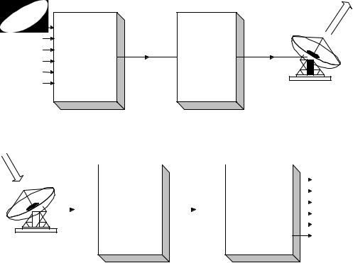
A typical application of the algorithm is shown in Figure 1.1. In this example, a 5.1 channel audio program is converted from a PCM representation requiring more than 5 Mbps (6 channels × 48 kHz × 18 bits = 5.184 Mbps) into a 384 kbps serial bit stream by the AC-3 encoder. Satellite transmission equipment converts this bit stream to an RF transmission which is directed to a satellite transponder. The amount of bandwidth and power required by the transmission has been reduced by more than a factor of 13 by the AC-3 digital compression. The signal received from the satellite is demodulated back into the 384 kbps serial bit stream, and decoded by the AC-3 decoder. The result is the original 5.1 channel audio program.
Digital compression of audio is useful wherever there is an economic benefit to be obtained by reducing the amount of digital information required to represent the audio. Typical applications are in satellite or terrestrial audio broadcasting, delivery of audio over metallic or optical cables, or storage of audio on magnetic, optical, semiconductor, or other storage media.
1.2 Encoding
The AC-3 encoder accepts PCM audio and produces an encoded bit stream consistent with this standard. The specifics of the audio encoding process are not normative requirements of this standard. Nevertheless, the encoder must produce a bit stream matching the syntax described in Section 5, which, when decoded according to Sections 6 and 7, produces audio of sufficient quality for the intended application. Section 8 contains informative information on the encoding process. The encoding process is briefly described below.
The AC-3 algorithm achieves high coding gain (the ratio of the input bit-rate to the output bit-rate) by coarsely quantizing a frequency domain representation of the audio
— 2 —
ATSC |
Digital Audio Compression (AC-3) Standard |
20 Dec 95 |
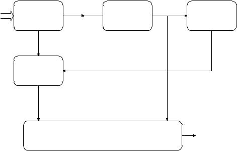
signal. A block diagram of this process is shown in Figure 1.2. The first step in the encoding process is to transform the representation of audio from a sequence of PCM time samples into a sequence of blocks of frequency coefficients. This is done in the analysis filter bank. Overlapping blocks of 512 time samples are multiplied by a time window and transformed into the frequency domain. Due to the overlapping blocks, each PCM input sample is represented in two sequential transformed blocks. The frequency domain representation may then be decimated by a factor of two so that each block contains 256 frequency coefficients. The individual frequency coefficients are represented in binary exponential notation as a binary exponent and a mantissa. The set of exponents is encoded into a coarse representation of the signal spectrum which is referred to as the spectral envelope. This spectral envelope is used by the core bit allocation routine which determines how many bits to use to encode each individual mantissa. The spectral envelope and the coarsely quantized mantissas for 6 audio blocks (1536 audio samples) are formatted into an AC-3 frame. The AC-3 bit stream is a sequence of AC-3 frames.
The actual AC-3 encoder is more complex than indicated in Figure 1.2. The following functions not shown above are also included:
1.A frame header is attached which contains information (bit-rate, sample rate, number of encoded channels, etc.) required to synchronize to and decode the encoded bit stream.
Transmission
Input Audio |
|
|
|
Signals |
|
|
|
Left |
Encoded |
|
|
Center |
|
|
|
Bit-Stream |
|
Modulated |
|
Right |
384 kb/s |
Transmission |
Signal |
AC-3 Encoder |
|
||
Left Surround |
Equipment |
|
|
|
|
||
Right Surround |
|
|
|
Low Frequency |
|
|
|
Effects |
|
|
Satellite Dish |
Reception
|
|
|
|
|
|
|
|
|
|
|
|
|
|
Output Audio |
|
|
|
|
|
|
|
|
|
|
|
|
|
|
|
Signals |
|
|
|
|
|
|
|
|
|
|
|
|
|
|
|
||
|
|
|
|
|
|
|
|
Encoded |
|
|
|
Left |
|||
|
|
|
|
|
|
|
|
|
|
|
|||||
|
|
|
|
|
|
|
|
|
|
|
Center |
||||
|
|
Modulated |
|
|
Bit-Stream |
|
|
|
|||||||
|
|
|
|
|
|
|
|||||||||
|
|
Signal |
Reception |
|
384 kb/s |
|
|
|
Right |
||||||
|
|
|
|
|
|
|
|
|
|
AC-3 Decoder |
|
||||
|
|
|
|
|
|
Equipment |
|
|
|
|
|
Left Surround |
|||
|
|
|
|
|
|
|
|
|
|
|
|
|
|||
|
|
|
|
|
|
|
|
|
|
|
|
|
|
|
Right Surround |
|
|
|
|
|
|
|
|
|
|
|
|
|
|
|
|
|
|
|
|
|
|
|
|
|
|
|
|
|
|
|
|
Satellite Dish
Low Frequency
Effects
Figure 1.1. Example application of AC-3 to satellite audio transmission.
— 3 —
ATSC |
Digital Audio Compression (AC-3) Standard |
20 Dec 95 |
PCM Time |
Analysis Filter |
Exponents |
Spectral |
|
|
Envelope |
Bit Allocation |
||
Samples |
Bank |
|
||
|
Encoding |
|
||
|
|
|
|
|
|
Mantissas |
|
|
|
|
Mantissa |
Bit Allocation Information |
|
|
|
Quantization |
|
|
|
|
Quantized |
Encoded |
|
|
|
Mantissas |
|
||
|
Spectral |
|
||
|
|
|
|
|
|
|
|
Envelope |
|
AC-3 Frame Formatting
Encoded AC-3
Bit-Stream
Figure 1.2. The AC-3 encoder.
2.Error detection codes are inserted in order to allow the decoder to verify that a received frame of data is error free.
3.The analysis filterbank spectral resolution may be dynamically altered so as to better match the time/frequency characteristic of each audio block.
4.The spectral envelope may be encoded with variable time/frequency resolution.
5.A more complex bit allocation may be performed, and parameters of the core bit allocation routine modified so as to produce a more optimum bit allocation.
6.The channels may be coupled together at high frequencies in order to achieve higher coding gain for operation at lower bit-rates.
7.In the two-channel mode a rematrixing process may be selectively performed in order to provide additional coding gain, and to allow improved results to be obtained in the event that the two-channel signal is decoded with a matrix surround decoder.
1.3 Decoding
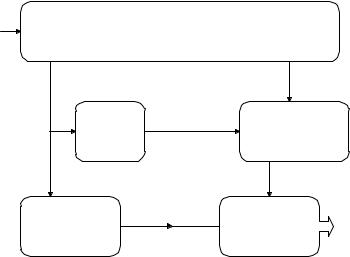
The decoding process is basically the inverse of the encoding process. The decoder, shown in Figure 1.3, must synchronize to the encoded bit stream, check for errors, and de-format the various types of data such as the encoded spectral envelope and the quantized mantissas. The bit allocation routine is run and the results used to unpack and de-quantize the mantissas. The spectral envelope is decoded to produce the exponents. The exponents and mantissas are transformed back into the time domain to produce the decoded PCM time samples.
— 4 —
ATSC |
Digital Audio Compression (AC-3) Standard |
20 Dec 95 |
Encoded AC-3 |
|
AC-3 Frame Syncronization, Error Detection, |
|
||||
Bit-Stream |
|
|
and |
Frame De-formatting |
|
||
|
|
|
|
|
Quantized |
||
|
|
|
|
Bit Allocation |
Mantissas |
||
Encoded |
|
Bit |
Mantissa |
|
|||
|
Information |
|
|||||
Spectral |
|
|
|
||||
|
Allocation |
De-quantization |
|||||
Envelope |
|||||||
|
|
|
|
|
|||
|
|
|
|
Mantissas |
|
||
|
Spectral |
|
Exponents |
Synthesis |
PCM Time |
||
|
Envelope |
|
|
||||
|
|
|
Filter Bank |
Samples |
|||
|
Decoding |
|
|
||||
|
|
|
|
|
|||
Figure 1.3. The AC-3 decoder.
The actual AC-3 decoder is more complex than indicated in Figure 1.3. The following functions not shown above are included:
1.Error concealment or muting may be applied in case a data error is detected.
2.Channels which have had their high-frequency content coupled together must be decoupled.
3.Dematrixing must be applied (in the 2-channel mode) whenever the channels have been rematrixed.
4.The synthesis filterbank resolution must be dynamically altered in the same manner as the encoder analysis filter bank had been during the encoding process.
— 5 —
ATSC |
Digital Audio Compression (AC-3) Standard |
20 Dec 95 |
2. SCOPE
The normative portions of this standard specify a coded representation of audio information, and specify the decoding process. Informative information on the encoding process is included. The coded representation specified herein is suitable for use in digital audio transmission and storage applications. The coded representation may convey from 1 to 5 full bandwidth audio channels, along with a low frequency enhancement channel. A wide range of encoded bit-rates is supported by this specification.
A short form designation of this audio coding algorithm is “AC-3”.
3. REFERENCES
3.1 Normative references
The following documents contain provisions which, through reference in this text, constitute provisions of this standard. At the time of publication, the editions indicated were valid. All standards are subject to revision, and parties to agreement based on this standard are encouraged to investigate the possibility of applying the most recent editions of the documents listed below.
None.
3.2 Informative references
The following documents contain information on the algorithm described in this standard, and may be useful to those who are using or attempting to understand this standard. In the case of conflicting information, the information contained in this standard should be considered correct.
Todd, C. et. al., “AC-3: Flexible Perceptual Coding for Audio Transmission and Storage”, AES 96th Convention, Preprint 3796, Feb. 1994.
Ehmer, R. H., "Masking Patterns of Tones," J. Acoust. Soc. Am., vol. 31, pp. 1115-1120 (1959 Aug.).
Ehmer, R H., "Masking of Tones vs. Noise Bands," J. Acoust. Soc. Am., vol. 31, pp 1253-1256 (1959 Sept.).
Moore, B.C.J., and Glasberg, B.R., “Formulae Describing Frequency Selectivity as a Function of Frequency and Level, and Their Use in Calculating Excitation Patterns,” Hearing Research, Vol. 28, pp. 209-225 (1987).
Zwicker, E. “Subdivision of the Audible Frequency Range into Critical Bands (Frequenzgruppen),” J.Acoust. Soc. of Am., Vol. 33, p. 248 (Feb. 1961).
— 6 —
ATSC |
Digital Audio Compression (AC-3) Standard |
20 Dec 95 |
4. NOTATION, DEFINITIONS, AND TERMINOLOGY
4.1 Compliance notation
As used in this document, “must”, “shall” or “will” denotes a mandatory provision of this standard. “Should” denotes a provision that is recommended but not mandatory. “May” denotes a feature whose presence does not preclude compliance, and that may or may not be present at the option of theimplementor.
4.2 Definitions
A number of terms are used in this document. Below are definitions which explain the meaning of some of the terms which are used.
audio block: |
A set of 512 audio samples consisting of 256 samples of the preceding audio |
|
block, and 256 new time samples. A new audio block occurs every 256 audio |
|
samples. Each audio sample is represented in two audio blocks. |
bin: |
The number of the frequency coefficient, as in frequency bin number n. The |
|
512 point TDAC transform produces 256 frequency coefficients or frequency |
|
bins. |
coefficient: |
The time domain samples are converted into frequency domain coefficients |
|
by the transform. |
coupled channel: |
A full bandwidth channel whose high frequency information is combined |
|
into the coupling channel. |
coupling band: |
A band of coupling channel transform coefficients covering one or more |
|
coupling channel sub-bands. |
coupling channel: |
The channel formed by combining the high frequency information from the |
|
coupled channels. |
coupling sub-band: |
A sub-band consisting of a group of 12 coupling channel transform |
|
coefficients. |
downmixing: |
Combining (or mixing down) the content of n original channels to produce |
|
m channels, where m<n. |
exponent set: |
The set of exponents for an independent channel, for the coupling channel, |
|
or for the low frequency portion of a coupled channel. |
full bandwidth (fbw) |
An audio channel capable of full audio bandwidth. All channels (left, center, |
channel: |
right, left surround, right surround) except thelfe channel are fbw channels. |
independent channel: |
A channel whose high frequency information is not combined into the |
|
coupling channel. (Thelfe channel is always independent.) |
low frequency effects lfe)( |
An optional single channel of limited (<120 Hz) bandwidth, which is |
channel: |
intended to be reproduced at a level +10 dB with respect to the fbw channels. |
|
The optional lfe channel allows high sound pressure levels to be provided for |
|
low frequency sounds. |
spectral envelope: |
A spectral estimate consisting of the set of exponents obtained by decoding |
|
the encoded exponents. Similar (but not identical) to the original set of |
|
exponents. |
synchronization frame: |
A unit of the serial bit stream capable of being fully decoded. The |
|
synchronization frame begins with a sync code and contains 1536 coded |
|
audio samples. |
— 7 —
ATSC |
Digital Audio Compression (AC-3) Standard |
20 Dec 95 |
window: |
A time vector which is multiplied by an audio block to provide a windowed |
|
|
audio block. The window shape establishes the frequency selectivity of the |
|
|
filterbank, and provides for the proper overlap/add characteristic to avoid |
|
|
blocking artifacts. |
|
4.3 Terminology abbreviations
A number of abbreviations are used to refer to elements employed in the AC-3 format. The following list is a cross reference from each abbreviation to the terminology which it represents. For most items, a reference to further information is provided. This document makes extensive use of these abbreviations. The abbreviations are lower case with a maximum length of 12 characters, and are suitable for use in either high level or assembly language computer software coding. Those who implement this standard are encouraged to use these same abbreviations in any computer source code, or other hardware or software implementation documentation.
Abbreviation acmod
addbsi addbsie addbsil audblk audprodie audprodi2e auxbits auxdata auxdatae auxdatal baie
bap bin blk blksw bnd bsi bsid bsmod ch
chbwcod chexpstr chincpl chmant clev cmixlev compr compr2 compre
Terminology audio coding mode
additional bit stream information additional bit stream information exists additional bit stream information length audio block
audio production information exists audio production information exists, ch2 auxiliary data bits
auxiliary data field auxiliary data exists auxiliary data length
bit allocation information exists bit allocation pointer
frequency coefficient bin in index bin[ ] block in array index [blk]
block switch flag
band in array index [bnd] bit stream information bit stream identification bit stream mode
channel in array index [ch] channel bandwidth code channel exponent strategy channel in coupling channel mantissas
center mixing level coefficient center mix level
compression gain word compression gain word, ch2 compression gain word exists
Reference
Section 5.4.2.3 on page21 Section 5.4.2.31 on page26 Section 5.4.2.29 on page26 Section 5.4.2.30 on page26 Section 5.4.3 on page26 Section 5.4.2.13 on page23 Section 5.4.2.21 on page24 Section 5.4.4.1 on page36 Section 5.4.4.1 on page36 Section 5.4.4.3 on page36 Section 5.4.4.2 on page36 Section 5.4.3.30 on page31
Section 5.4.3.13 on page28
Section 5.4.3.1 on page26
Section 5.4.2 on page20 Section 5.4.2.1 on page20 Section 5.4.2.2 on page20
Section 5.4.3.24 on page30 Section 5.4.3.22 on page30 Section 5.4.3.9 on page27 Section 5.4.3.61 on page35 Section 5.4.2.4 on page21 Section 5.4.2.4 on page21 Section 5.4.2.10 on page23 Section 5.4.2.18 on page24 Section 5.4.2.9 on page22
— 8 —
ATSC |
Digital Audio Compression (AC-3) Standard |
20 Dec 95 |
Abbreviation |
Terminology |
compr2e |
compression gain word exists, ch2 |
copyrightb |
copyright bit |
cplabsexp |
coupling absolute exponent |
cplbegf |
coupling begin frequency code |
cplbndstrc |
coupling band structure |
cplco |
coupling coordinate |
cplcoe |
coupling coordinates exist |
cplcoexp |
coupling coordinate exponent |
cplcomant |
coupling coordinate mantissa |
cpldeltba |
coupling dba |
cpldeltbae |
coupling dba exists |
cpldeltlen |
coupling dba length |
cpldeltnseg |
coupling dba number of segments |
cpldeltoffst |
coupling dba offset |
cplendf |
coupling end frequency code |
cplexps |
coupling exponents |
cplexpstr |
coupling exponent strategy |
cplfgaincod |
coupling fast gain code |
cplfleak |
coupling fast leak initialization |
cplfsnroffst |
coupling fine SNR offset |
cplinu |
coupling in use |
cplleake |
coupling leak initialization exists |
cplmant |
coupling mantissas |
cplsleak |
coupling slow leak initialization |
cplstre |
coupling strategy exists |
crc1 |
crc - cyclic redundancy check word 1 |
crc2 |
crc - cyclic redundancy check word 2 |
crcrsv |
crc reserved bit |
csnroffst |
coarse SNR offset |
d15 |
d15 exponent coding mode |
d25 |
d25 exponent coding mode |
d45 |
d45 exponent coding mode |
dba |
delta bit allocation |
dbpbcod |
dB per bit code |
deltba |
channel dba |
deltbae |
channel dba exists |
deltbaie |
dba information exists |
deltlen |
channel dba length |
deltnseg |
channel dba number of segments |
deltoffst |
channel dba offset |
dialnorm |
dialogue normalization word |
dialnorm2 |
dialogue normalization word, ch2 |
dithflag |
dither flag |
dsurmod |
Dolby surround mode |
dynrng |
dynamic range gain word |
dynrng2 |
dynamic range gain word, ch2 |
dynrnge |
dynamic range gain word exists |
dynrng2e |
dynamic range gain word exists, ch2 |
exps |
channel exponents |
Reference
Section 5.4.2.17 on page24 Section 5.4.2.24 on page25 Section 5.4.3.25 on page30 Section 5.4.3.11 on page27 Section 5.4.3.13 on page28 Section 7.4.3 on page71 Section 5.4.3.14 on page28 Section 5.4.3.16 on page29 Section 5.4.3.17 on page29 Section 5.4.3.53 on page34 Section 5.4.3.48 on page33 Section 5.4.3.52 on page34 Section 5.4.3.50 on page33 Section 5.4.3.51 on page33 Section 5.4.3.12 on page27 Section 5.4.3.26 on page30 Section 5.4.3.21 on page30 Section 5.4.3.39 on page32 Section 5.4.3.45 on page33 Section 5.4.3.38 on page32 Section 5.4.3.8 on page27 Section 5.4.3.44 on page32 Section 5.4.3.61 on page35 Section 5.4.3.46 on page33 Section 5.4.3.7 on page27 Section 5.4.1.2 on page19 Section 5.4.5.2 on page36 Section 5.4.5.1 on page36 Section 5.4.3.37 on page32 Section 5.4.3.21 on page30 Section 5.4.3.21 on page30 Section 5.4.3.21 on page30 Section 5.4.3.47 on page33 Section 5.4.3.34 on page31 Section 5.4.3.57 on page34 Section 5.4.3.49 on page33 Section 5.4.3.47 on page33 Section 5.4.3.56 on page34 Section 5.4.3.54 on page34 Section 5.4.3.55 on page34 Section 5.4.2.8 on page22 Section 5.4.2.16 on page24 Section 5.4.3.2 on page26 Section 5.4.2.6 on page22 Section 5.4.3.4 on page26 Section 5.4.3.6 on page27 Section 5.4.3.3 on page26 Section 5.4.3.5 on page27 Section 5.4.3.27 on page31
— 9 —
ATSC |
Digital Audio Compression (AC-3) Standard |
20 Dec 95 |
Abbreviation |
Terminology |
fbw |
full bandwidth |
fdcycod |
fast decay code |
fgaincod |
channel fast gain code |
floorcod |
masking floor code |
floortab |
masking floor table |
frmsizecod |
frame size code |
fscod |
sampling frequency code |
fsnroffst |
channel fine SNR offset |
gainrng |
channel gain range code |
grp |
group in index [grp] |
langcod |
language code |
langcod2 |
language code, ch2 |
langcode |
language code exists |
langcod2e |
language code exists, ch2 |
lfe |
low frequency effects |
lfeexps |
lfe exponents |
lfeexpstr |
lfe exponent strategy |
lfefgaincod |
lfe fast gain code |
lfefsnroffst |
lfe fine SNR offset |
lfemant |
lfe mantissas |
lfeon |
lfe on |
mixlevel |
mixing level |
mixlevel2 |
mixing level, ch2 |
mstrcplco |
master coupling coordinate |
nauxbits |
number of auxiliary bits |
nchans |
number of channels |
nchgrps |
number of fbw channel exponent groups |
nchmant |
number of fbw channel mantissas |
ncplbnd |
number of structured coupled bands |
ncplgrps |
number of coupled exponent groups |
ncplmant |
number of coupled mantissas |
ncplsubnd |
number of coupling sub-bands |
nfchans |
number of fbw channels |
nlfegrps |
number of lfe channel exponent groups |
nlfemant |
number of lfe channel mantissas |
origbs |
original bit stream |
phsflg |
phase flag |
phsflginu |
phase flags in use |
rbnd |
rematrix band in index [rbnd] |
rematflg |
rematrix flag |
rematstr |
rematrixing strategy |
roomtyp |
room type |
roomtyp2 |
room type, ch2 |
sbnd |
sub-band in index [sbnd] |
sdcycod |
slow decay code |
seg |
segment in index [seg] |
sgaincod |
slow gain code |
skipfld |
skip field |
skipl |
skip length |
Reference
Section 5.4.3.32 on page31 Section 5.4.3.41 on page32 Section 5.4.3.35 on page32 Section 7.2.2.7 on page57 Section 5.4.1.4 on page20 Section 5.4.1.3 on page19 Section 5.4.3.40 on page32 Section 5.4.3.28 on page31
Section 5.4.2.12 on page23 Section 5.4.2.20 on page24 Section 5.4.2.11 on page23 Section 5.4.2.19 on page24
Section 5.4.3.29 on page31 Section 5.4.3.23 on page30 Section 5.4.3.43 on page32 Section 5.4.3.42 on page32 Section 5.4.3.63 on page35 Section 5.4.2.7 on page22 Section 5.4.2.14 on page23 Section 5.4.2.22 on page24 Section 5.4.3.15 on page28 Section 5.4.4.1 on page36 Section 5.4.2.3 on page21 Section 5.4.3.27 on page31 Section 5.4.3.61 on page35 Section 5.4.3.13 on page28 Section 5.4.3.26 on page30 Section 5.4.3.62 on page35 Section 5.4.3.12 on page27 Section 5.4.2.3 on page21 Section 5.4.3.29 on page31 Section 5.4.3.63 on page35 Section 5.4.2.25 on page25 Section 5.4.3.18 on page29 Section 5.4.3.10 on page27
Section 5.4.3.20 on page29 Section 5.4.3.19 on page29 Section 5.4.2.15 on page23 Section 5.4.2.23 on page25
Section 5.4.3.31 on page31
Section 5.4.3.33 on page31 Section 5.4.3.60 on page35 Section 5.4.3.59 on page35
— 10 —