

Atmel applications journal.Summer 2004
.pdfA T M E L A P P L I C A T I O N S J O U R N A L
Figure 1: The DiveMate’s schematic illustrates the simplicity of the hardware design.
water pressure without causing the box to leak. Dan Andrews, a mechanical engineer whom I work with, provided the solution. He created a small, threaded metal orifice that screws into a threaded hole drilled through the plastic case. One end of a piece of surgical tubing is placed on a fitting inside the orifice, and the other end is placed on a fitting on the pressure sensor. This way, the sensor has access to the surrounding water while the electronics stay safe and dry.
The DiveMate’s UART and ISP pins are multiplexed onto a common 6-pin header, J1 (see Figure 1). An external circuit, illustrated in Figure 2, allows the DiveMate to connect to a PC’s serial port via J1 to perform configuration or data transfer. The primary component of this circuit is the Dallas DS275, a line-powered RS-232 transceiver chip. This 8-pin chip performs the voltage level shifting required to interface to a PC’s serial port. Although not shown, header J1 also allows in-system programming of the AVR via an external cable connected to a device programmer.
An 8 x 2 LCD provides immediate feedback of depth, temperature, surface interval time, and communication link status, depending on the operation mode. The display’s 4-bit Bus mode makes it a feasible option even on microcontrollers with low pin counts. Likewise, its small size makes it suitable for use in space-constrained devices.
Transistors Q1 and Q3 along with switch S1 comprise a power control circuit (see Figure 1). You can activate the DiveMate, but the AVR powers down the device. To activate, you press the switch, which powers the LDO regulator, which in turn powers the rest of the DiveMate circuitry. Immediately after powerup, the AVR sets the output connected to the gate of Q3, an N-channel FET, high. This pulls down the gate of Q1, a P-channel FET, activating it and bypassing S1 so that the circuit remains powered even when the switch is released. At this point, the AVR can power down the circuit at any time by pulling the gate of Q3 low. Although not electrical in nature, one of the most challenging aspects of this project was finding a method to enclose the electronics that would keep them dry and intact at high pressures and allow the pressure sensor access to ambient water pressure. An early idea that held promise involved potting the entire electronics assembly in an epoxy resin, rendering the electronics waterproof and highly
pressure-resistant. The drawback is that there would be no access after the electronics were potted; something as simple as a battery change would be nearly impossible.
The solution to this challenge came in two parts. I’d like to thank my wife Christine for finding the perfect enclosure while flipping through a diving supply catalog. The Otter Box is a small (approximately 4.5” x 3” x 1.5”), clear plastic enclosure with an O-ring seal that’s rated watertight up to 100 feet. Although short of the 130 feet recreational dive limit, the box is ideal in all other respects.
The second part of the enclosure problem was how to provide the pressure sensor access to external
Firmware note
Although there isn’t enough space for a detailed discussion about the firmware, there are a few points worth mentioning. As with the majority of embedded projects, the firmware development took far longer than the hardware development. The DiveMate’s firmware was written 100% in assembly. Although ideal for interfacing to devices and writing small, tight code, assembly isn’t well suited for manipulating complex data structures like higher-level languages, such as C.
Accordingly, the most difficult routines to implement and debug were those that deal with storing dive record data structures. Although I wouldn’t have had enough code space to implement all of the features that I included had I developed the firmware solely
Figure 2: Because the RS-232 driver is required only when the DiveMate is connected to a PC, it was placed on its own board. This frees space on the DiveMate board and reduces its operational power requirements.
www.atmel.com |
page 19 |
|
A T M E L A P P L I C A T I O N S J O U R N A L
in C, a C and assembly mixture may have been feasible.
Let’s Get Wet
By last September, the DiveMate was ready for in-water trials. On September 10, my dive buddies and I headed off to our favorite local dive spot, New River near Blacksburg, VA. As we descended, I was pleased to see the DiveMate switch into Dive mode and begin displaying depth and temperature. I was even more pleased when the DiveMate’s depth measurement matched that of the other two depth gauges I had with me. Likewise, the measured temperature was close to what the redundant gauge reported. All was well…until we hit 20 feet. I felt and heard a sudden pop. Imagine my horror as I observed the enclosure filling with water. A postmortem revealed that the fitting on the pressure sensor had snapped off because of lateral force. The sensor had been firmly lodged against the inside wall of the case, which bowed slightly under the 23 psi experienced, snapping off the fitting.
After some minor modifications that left more space between the pressure sensor and case wall,
it was time for attempt number two. On September 23, we headed back to the river. This time we hit 40 feet and the DiveMate was working perfectly… until about 20 minutes into the dive when the display went out. Back on dry land, a bit of prodding revealed that the modified display connector wasn’t making good contact. I fixed this problem by hardwiring the display in place.
October 7 was the next chance to hit the water. This time, the DiveMate performed flawlessly throughout the 40 minute dive. The plot of the data downloaded following the dive is shown in Figure 3. I gradually reached a depth just short of 40 feet as I followed the bottom to the center of the river. I then ascended to a depth of 30 feet to cruise alongside some submerged trees. At the 20 minute mark, I ascended along a rock wall to 25 feet, spying a huge catfish in a crevice. I headed back down to the bottom and then followed it to the other side of the river. At the 33 minutes mark, I surfaced on the far side.
During the 6 minutes I spent on the surface, I swam back across to the exit point. Then, I submerged for a few minutes to verify that the DiveMate would once again enter Dive mode. I repeated the exercise
before exiting the water at about the 40 nute mark. As is evident from the plot, the water was about 64° F. I was able to squeeze in two more test dives later in October before the water got too cold to enter in a wet suit. Each time the DiveMate performed flawlessly.
Final Comments
After my experiences developing this project, I highly recommend the AVR microcontroller. Its powerful, consistent architecture makes it a pleasure to use. Additionally, a development system can be put together inexpensively. The assembler and simulator are free from Atmel’s web site. Free plans and software for device programmers also are readily available on the Internet. Before choosing a microcontroller for your next project, be sure to take a good look at the AVR.
Developing the DiveMate has been a frustrating, challenging, yet rewarding experience. The project required a great deal of perseverance and patience in addition to many late nights. Now, it’s gratifying to see it functioning as desired under 40 feet of water at the bottom of a dark, cold river. The DiveMate is just one more example that 8-bit micros can thrive nearly anywhere. 
Integrated Development Tools for Embedded Microcontrollers
Atmel: T89C51RB2/RC2/RD2, T89C5111/5112/5115, T89C51AC2, T89C51CC01/02/03, TS8xC51U2, AT8xLV51/52/55, AT87F51/52/55, AT89C1051/2051/2051x2/4051, AT89C51/52/55/55WD, T89C51IB2/ IC2, AT87F51RC, TS8xC51RA2, AT90S, ATtiny and others…
Philips: LPC760/761/762/764/767/768/769, LPC932/9xx, 80C31X2/ 51X2/52X2/54X2/58X2, 89C51RA2/RB2/RC2/RD2, 8xC660/662/664/ 668, P87C552/554, 87C652/654 and others…
Intel: 80C31/32/51/52, 87C51FA/FB/FC, 87C51RA/RB/RC, 8xC196KC/ KD, 8xC196MC/MD/MH, 8xC196CB, 8xC196NT and others…
Winbond: W77C32/58; W77E58, W77L32, W77LE58, W78C54, W78C58, W78E516B, W78E51B, W78E52B/54/58, W78IE54, W78L51/ 52/54, W78LE51/52/54/58, W78LE516/532, W78LE52, W78LE54, W78C51D, others…
Dallas Semiconductor:DS87C310/320/520/530 and others…
SST: 89C59, 89F54, 89F58 and others…
Microchip: The entire PIC12, PIC16, PIC17, and PIC18 families including PIC16F627/628, PIC17C756, PIC16F877A, PIC16F818/819, PIC18F452, PIC18F458, PIC18F6620, PIC18F6720, PIC18F8620, PIC18F8720, PIC18F4320 and others…
Texas Instruments: The entire MSP430 family, TAS1020A, TUSB3220
Xemics: XE88LC01/05, XE88LC02, XE88LC06/06A
Sensory: RSC4xx
Hi-End Features @ Affordable Prices
www.atmel.com |
page 20 |
|

A T M E L A P P L I C A T I O N S J O U R N A L
A SINGLE USB PORT CAN BE USED TO CONNECT UP TO 127 PERIPHERALS DEVICES WITHOUT HAVING TO ADD AN ADAPTER OR EVEN TURN OFF THE COMPUTER.
89C5131 USB Microcontoller
Atmel offers an extensive portfolio of USB products that include USB hubs, microcontollers with integrated USB interface, and embedded USB hosts.
These devices are designed specifically to hide the complexities of USB protocol form your embedded design. The availability of the USB firmware library, sample code, and software design tools such as the USB Wizard (a GUI based source code generator) further reduces your learning curve and ensures the shortest design.
Building a RS-232 to USB Bridge Using a AT89C5131 Microcontroller
By Michael Panfil
Long live the RS-232 COM port! In the world of personal computers, the RS-232 COM port is disappearing, especially with laptops. The age-old serial port interface is being replaced by the USB, a bus that supports higher speeds and is significantly more flexible. The final USB-capable application can use the flexibility of the USB with its data buffering and automatic flow control. The USB link offers a power supply for the application. The overwhelming success of this simple universal serial PC interface is also due to its plug-and-play and hot plugging capabilities. A single USB port can be used to connect up to 127 peripherals devices without having to add an adapter or even turn off the computer. Furthermore, USB is expected to completely replace other serial, parallel and game interfaces in PC and peripherals markets. USB connectivity can be found in a wide range of devices and markets nowadays including industrial equipment and data acquisition, security
applications (i.e. |
ID mouse, smart |
||
card reader), |
(i.e. Flash disk), |
||
communication |
mobile phone), and |
||
PC and peripherals |
|
key-board, |
|
audio and game |
|
|
|
As the world |
|
to USB, there |
|
is still a |
issue - There are |
||
still many legacy |
use the RS-232 |
||
|
|
|
|
|
|
|
|
|
|
|
|
|
|
|
|
standard. The obvious solution is to make the USB bus appear as an RS-232 interface (Figure 1). The obvious advantages of this masquerade are that there will be no need to change the PC application and fewer modifications are required for the embedded hardware and software.
Making the Switch
There are several ways to make the switch from RS-232 to USB, but the aim is to perform this switch with a minimum time and effort. With the Atmel USB RS-232 Virtual COM port library, you can easily build an RS-232 to USB gateway. This gateway uses the USB Communication Device Class (CDC) drivers to take advantage of the installed PC RS-232 software to talk over the USB. The CDC document, available at www.usb.org, describes a way to implement devices such as ISDN modems and virtual COM ports. The CDC class is implemented in all releases of Windows, from Windows 98SE to Windows XP.
The 89C5131 is a high-performance Flash version of the 80C51 single-chip 8-bit micocontroller with full speed USB funcions. It features a full-speed USB compatible with the USB specifications Version 1.1 and 2.0. This module integrates the USB tranceivers with a 3.3V voltage regulator and the Serial Interface Engine with Digital Phase Locked Loop and 48 MHz clock recovery.
800 |
|
|
|
|
|
Millions of |
|
|
|
|
|
Units |
|
|
|
|
|
600 |
|
|
|
|
|
400 |
|
|
|
|
|
200 |
|
|
|
|
|
0 |
|
|
|
|
|
2001 |
2002 |
2003 |
2004 |
2005 |
2006 |
Forecast for USB-enabled Devices
Source: In-Stat/MDR 2002
Figure 1: The aim of a Virtual COM port implementation is to move from a real UART system to a UART-USB system
www.atmel.com |
page 21 |
|

A T M E L A P P L I C A T I O N S J O U R N A L
The architecture of this gateway requires very few modifications. On the PC side, there is nothing to change! The PC views the USB device as a COM port and the application doesn’t need to be changed. On the embedded side, UART USB drivers replace the UART driver. The embedded application simply calls UART-USB functions instead of UART functions. In order to be considered a COM port, the USB device declares 2 interfaces: (1) Abstract Control Model Communication, with 1 Interrupt IN endpoint; and (2) Abstract Control Model Data, with 1 Bulk IN and 1 Bulk OUT endpoint.
When plugging in a new USB device, Windows checks all its INF files to load the appropriate driver. The INF file contains the Vendor ID (VID), the Product ID (PID), or the USB Class definition. If the VID/PID or the USB Class Definition of the USB device matches with an INF file, Windows will load the driver described in this file. But Microsoft does not provide a standard INF file for the CDC driver, so Atmel provides an INF file that allows this driver to load under Windows 2000 and Windows XP. When plugged in for the first time, the user instructs the Operating System which driver to use by selecting this INF file. The application manufacturer, using its own VID and PID, modifies these values in the embedded application (in the config.h file) and the INF file given in the example on this page.
Modifying the Embedded Application Firmware
From a hardware perspective, the USB to UART bridge can be implemented using Atmel’s AT89C5131 microcontroller with one of its 7 USB endpoints. The embedded firmware must be modified to include an intermediate buffer that will handle data in the event that the USB is not ready (Figure 2). The software modules required to implement all the embedded firmware are available on Atmel’s website.
According to a 2002 report by In-Stat/MDR, almost 800 million devices will be USB enabled by 2006. Obviously, this implies that many new devices will not require the RS-232 to USB bridging. However, it’s good to know that there’s a relatively simple solution for all the legacy devices with only a UART interface. 
Figure 2: In this implementation, all characters received from the UART are stored in an intermediate buffer to avoid lost data when the USB is unable to handle the data.
Windows 2000 and XP Setup File for AT89C5131 Demo
[Version] Signature="$Windows NT$" Class=Ports
ClassGuid={4D36E978-E325-11CE-
BFC1-08002BE10318}
Provider=%ATMEL%
LayoutFile=layout.inf
DriverVer=10/15/1999,5.0.2153.1
[Manufacturer]
%ATMEL%=ATMEL
[ATMEL]
%ATMEL_CDC%=Reader, USB\VID_03EB&PID_2009
[Reader_Install.NTx86] ;Windows2000 [DestinationDirs] DefaultDestDir=12 Reader.NT.Copy=12 [Reader.NT] CopyFiles=Reader.NT.Copy AddReg=Reader.NT.AddReg
[Reader.NT.Copy]
usbser.sys
[Reader.NT.AddReg]
HKR,,DevLoader,,*ntkern
HKR,,NTMPDriver,,usbser.sys
HKR,,EnumPropPages32,,"MsPorts.dll
,SerialPortPropPageProvider"
[Reader.NT.Services]
AddService = usbser, 0x00000002, Service_Inst
[Service_Inst]
DisplayName = %Serial.SvcDesc%
ServiceType = 1 ; SERVICE_KER-
NEL_DRIVER
StartType = 3 ;
SERVICE_DEMAND_START
ErrorControl = 1 ;
SERVICE_ERROR_NORMAL
ServiceBinary = %12%\usbser.sys
LoadOrderGroup = Base
[Strings]
ATMEL = "ATMEL, Inc."
ATMEL_CDC = "AT89C5131 CDC USB to UART"
Serial.SvcDesc = "USB Serial emulation driver"
www.atmel.com |
page 22 |
|

A T M E L A P P L I C A T I O N S J O U R N A L
Designer’s 
Corner
MOST CHEFS WOULD ARGUE THAT BARBECUING IS MORE ART THAN SCIENCE. NEVERTHELESS, JOHN INTRODUCED ATMEGA8BASED TECHNOLOGY TO THE PROCEDURE. THE RESULT? AN AUTOMATIC TEMPERATURE CONTROLLER THAT ELIMINATES THE NEED FOR CONSTANT VIGILANCE WHEN SLOW COOKING.
Reprinted with permission of
Circuit Cellar
Issue 154
May 2003
Automatic Temperature Controller:
Designing a Data Logger for a Slow Cooker
By: John Moyer
A traditional barbecue typically involves cooking tough cuts of meat (e.g., pork ribs, pork shoulder, and beef brisket) over a wood or charcoal fire at a low temperature (200° to 250°F). The meat is cooked for long periods of time until it’s tender (e.g., 5 to 6 hours for ribs and 10 to 20 hours for brisket or pork shoulder). Usually, steel offset cookers, modified 55-gallon drums, and even in-ground pits are used.
Another barbecue tradition requires someone to be present for the 5 to 20 hours that the meat is cooking. This person must add fuel so the fire doesn’t go out and regulate the cooking temperature. Although modern technology can’t shorten barbecue-cooking times, it can eliminate the need for someone to be present to maintain the cooking temperature.
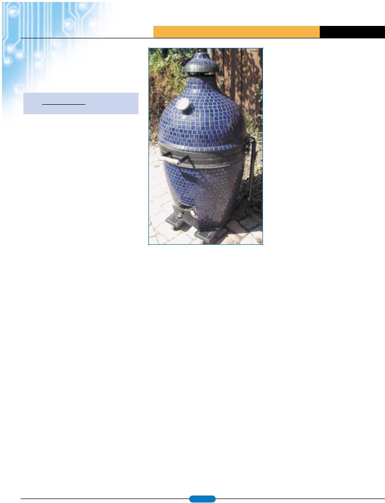
Ceramic Cookers
Photo 1 shows a different kind of cooker. The cooker’s thick ceramic walls do such a good job of insulating that a single load of lump charcoal fuel can maintain barbecue-cooking temperatures for more than 24 hours This neatly solves the problem of having to add fuel during a cooking session, but there’s still the issue of temperature regulation. The firebox is at the bottom of the cooker, and the temperature is adjusted using the lower and upper draft openings. Additional air moving through the cooker produces a bigger fire and higher temperature.
After it’s set for a given temperature, a ceramic cooker does a remarkable job of maintaining that temperature. However, if internal or external conditions shift too much (e.g., changes in the weather or wind, or ash buildup in the firebox), the draft settings must be adjusted in order to keep the temperature from changing. To have true hands-off temperature control, you need a closed-loop process control system. In such a system, the actual cooker temperature is monitored and used to adjust the airflow to maintain the desired temperature.
Project Goals
The original goal for this project was to implement a simple closed-loop temperature controller using an 8-bit microprocessor. Modeled after a kitchen oven,
A.
V+
D
G
Enable |
|
MOSFET switch |
|
|
V+ |
|
|
|
S |
|
|
|
|
|
|
|
|
V+ |
|
|
|
VOUT |
VOUT |
B. |
V+ |
|
D |
|
|
|
|
|
|
G |
|
|
G |
V+ |
|
|
|
|
V+ |
|
|
VOUT |
VOUT |
Figure 1a: With no thermocouple connected, a test voltage applied to the op-amp produces a maximum output voltage. b: The low impedance of a connected thermocouple drastically reduces the test voltage, producing a much lower
output voltage.
I wanted the controller to have a knob for setting the desired temperature. A temperature probe would monitor the ceramic cooker’s actual temperature, and the controller would adjust the airflow to keep the desired and actual temperatures as close as possible.
Being microprocessor controlled, I thought it would be easy to add other functionality, such as additional probes to monitor the food temperature, and another control to indicate the desired final food temperature. An alarm could ring when the food reached a desired temperature or if an error condition occurred. An RS-232 port would allow cooker and food temperatures to be logged, either to a local computer or perhaps a web site for remote access. Photo 2 shows the front panel of my final controller implementation.
As for the control system’s accuracy, my intention was make it at least as good as a kitchen oven. Temperature tolerances only needed to be within ±5°, because barbequing is more of an art than a science. Temperature is just one factor to be consider when you’re trying to determine if the food is ready to be taken off the fire.
www.atmel.com |
page 23 |
|

A T M E L A P P L I C A T I O N S J O U R N A L
Figure 2: The goal is to build a system that is comparable to or better than a kitchen oven. Atmel’s ATmega8 microcontroller is at the heart of the controller.
Temperature Acquisition
Temperatures are measured by taking an analog measurement from a temperature probe. Converting it to a digital value using the micro’s A/D converter, and then converting the raw measurement to an actual temperature achieves this.
The temperature probe I used is a thermocouple, which is constructed simply by connecting two dissimilar types of metal wire. When this junction is heated, a voltage proportional to the temperature can be measured at the other end of the wires. Different types of metals have been standardized, and their voltage-versus-tempera- ture properties characterized. This project uses a type-K thermocouple.
Generally, type-K can be used for temperatures up to 2300°F, although the insulating materials used in the low-cost probes limit the upper temperature to approximately 500°F for Teflon and 900° for glass braid. Photo 3 shows typical thermocouple configurations. Although thermocouples are simple, rugged, and inexpensive, they have some properties that must be accommodated.
Thermocouple Properties
First, the output voltage of a type-K thermocouple is only about 20 µV (i.e., 0.00002 V) per 1°F. This must be amplified in order to use the microprocessor’s A/D converter, but most
amplifiers aren’t suitable. General-purpose op-amps typically have input offset voltage errors of 1 to 5 mV, which corresponds to a temperature error of hundreds of degrees! The precision op-amp used instead has a maximum offset voltage error of only 5 µV, or less than a quarter-degree error. The amplifier circuit is configured for a gain of 111; therefore, by using a 2.5-V reference with the A/D converter, you can measure temperatures from 32° to roughly 1000°F with approximately 1° resolution.
Of course, if you were to amplify the thermocouple signal, you’d also amplify any noise signals in this not too carefully constructed circuit. You can minimize the effects of noise by taking multiple (32 to 256) A/D readings and averaging them to produce a single temperature measurement.
The second thermocouple problem is that output is nonlinear. You cannot perform a simple division to convert voltage to temperature. This is easily dealt with by storing the type-K voltage-to-temperature table in the controller software. [1] The 0° to 1000°F temperature range can be divided into approximately linear regions. You can use linear interpolation to determine a temperature within a given region.
The final thermocouple problem is that output is relative, not absolute. The voltage at the probe end of the thermocouple where the two dissimilar wires connect is relative to the voltage at the circuit end, where the thermocouple wires connect to the
voltage measurement circuit. If the probe and circuit ends have the same temperature, the measured voltage will be zero. If the probe end is hotter, a positive voltage will be measured. If it’s colder, a negative voltage will be measured.
Therefore, in order to know the actual temperature at the probe end, you need to know the temperature of the circuit end. Historically, this was accomplished by keeping the circuit end in an ice bath so its temperature remained 32°. Consequently, the connection between the thermocouple and measuring circuit came to be known as the “cold junction.” The process of using the junction temperature to calculate the actual probe temperature is referred to as cold junction compensation.
Instead of using ice, which is somewhat impractical for a barbecue application, you can use an IC temperature sensor to directly measure the actual temperature of the cold junction. For this to work, the sensor and physical connection point where the thermocouple wires meet the copper circuit wires must be the same temperature (i.e., isothermal). A difference in temperature will directly affect the accuracy of the temperature measurement. One method, which seems to work acceptably well, is shown in Photo 4.
Multiple Thermocouples
After you have the basic setup to measure one channel, it’s easy to add an analog multiplexer to select from one of several channels. However, in order to prevent false alarms from the alarm circuit, you need to know if a thermocouple is actually connected to a channel. The circuit shown in Figure 1 allows the microprocessor to determine this.
Temp Measurement
You must complete several steps to make a single temperature measurement. First, select the channel to be read by setting the analog multiplexer to one of the four thermocouples. Then, see if there is actually a thermocouple connected by turning on the missing thermocouple test voltage and taking an ADC measurement. Remember that a single measurement is actually the average of 32 to 256 readings.
If the result is the maximum A/D value, then there is no thermocouple connected to that channel, so report a temperature value of zero. Otherwise, turn off the missing thermocouple test voltage, and measure the actual thermocouple output.
www.atmel.com |
page 24 |
|
A T M E L A P P L I C A T I O N S J O U R N A L
Using the A/D reading, the amplifier gain (111), and the A/D voltage reference value (2.5 V), compute the actual thermocouple voltage. A 10-bit A/D reading will be in the 0- to 1023-V range, so the actual voltage is equal to the following:
A/D reading × 2.5
1024 × 111
Next, take and average multiple A/D readings of the cold junction temperature sensor, and convert that voltage to the cold junction temperature. Using the cold junction temperature and the type-K voltage/temperature table, compute the type-K voltage that’s equivalent to the cold junction temperature. Add the thermocouple voltage to the cold junction voltage. Using the type-K table, convert the summed thermocouple and cold junction voltages to the actual thermocouple temperature.
Measurement Accuracy
There are several sources for error in this process, including the inherent inaccuracies of the thermocouple and cold-junction temperature sensor, how isothermal the cold junction and sensor really are, the accuracies of the A/D converter and voltage reference, and gain errors in the amplifier. A good reality check is to test the temperature of boiling water, because 212°F is actually within the range of the typical barbecuecooking temperatures. The circuit and setup described here yielded a boiling water temperature of 213°F, which is good enough for barbecue purposes.
Design Limitation
The circuit has a design limitation. When the thermocouple probe is at a lower temperature than the cold junction, the voltage produced is negative. However, the circuit, as configured, is single-ended, so it treats a negative voltage as if it were 0 V.
Consequently, if the probe is colder than the cold junction, the computed temperature will be the cold junction temperature, not the actual probe temperature. There are several ways to correct this, but none were used, because I was only concerned with high temperatures, not low ones.
Airflow Control
Now you’re capable of measuring the cooker’s temperature, but how can you control it? Adjusting the lower or upper draft openings to regulate the
Photo 1: The door at the bottom opens and closes, and the cap at the top turns to regulate the cooker temperature, which is monitored
with a dial thermometer.
airflow would require a motorized mechanism. A simpler approach is to use a small fan.
Little airflow is required for barbecue-cooking temperatures. The 40-mm fan that I used only puts out 10 cubic feet per minute, but can produce cooker temperatures higher than 400°F. Although bigger fans can produce higher temperatures, they’re unnecessary for barbequing, and you don’t want to cook the electronics, which are mounted only a few inches from the firebox. The fan speed can be controlled by the microprocessor using one of its PWM outputs from fully on to off in 255 steps.
So little airflow is needed that air leaks can prevent low temperatures from being reached! There must be a good seal between the cooker’s lid and base. Also, you must prevent air from leaking in through the opening when the fan is off. The simple flapper valve, which is shown in Photo 5, accomplishes this; it’s constructed from a piece of aluminum pie pan that’s epoxy-glued to a small metal hinge. When the fan is on, it opens the aluminum flap. The flap shuts when the fan is off, sealing the opening.
Controller Electronics
Figure 2 shows the schematic for the controller. The microprocessor is an ATmega8, which has 8 KB of flash memory for program storage and 1 KB of RAM. The on-board oscillator is used at its default setting of 1 MHz, so a crystal or clock circuit isn’t needed. Four of its six A/D channels are used for the thermocouple amplifier output, LM34 temperature sensor, and potentiometers needed for the cooker and food temperature settings. Digital lines are used for the LCD, which has an HD44780-type interface, fan, analog multiplexer channel select, piezoelectric alarm, missing thermocouple detection circuit, and RS-232 connections.
The ATmega8 can be in-circuit programmed. Power is supplied through an unregulated 12-V wall wart or 12-V sealed lead-acid battery. Regulators are needed to convert this to 5 V for the electronics, a 2.5-V 0.2% precision reference voltage, and 12 V for the fan. The transistor that controls the fan must be rated according to the fan’s current requirements. The fan that I used draws 100 mA, so a 2N7000 MOSFET that can handle 200 mA is adequate. With a backlit LCD and the fan turned on, the current draw is only 120 mA, so a 7-Ah battery can power the controller for several days.
The RS-232 port is used primarily for data logging. Because the barbecue is usually outdoors and the computer indoors, a MAX232 and low data rate (i.e., 2400 bps) are used to allow for the greatest possible distance between the controller and data logger. Using six-conductor telephone cable with RJ11 to RS-232 modular connectors, distances of 100¢ are easily achieved. The alarm signal is also brought out on the RS-232 cable, so the outdoor on-board alarm can be muted at night, and a smaller piezo alarm that’s connected to the end of the cable can be placed indoors where someone is likely to hear it.
Photo 6 shows the electronics, which are mounted on the lid of a standard doublewide outdoor “wet location” electrical box. The box itself is mounted to the lower draft door of the cooker. The cover supplied with the box allows the controller to stay outdoors and mounted on the cooker at all times. Alternate packaging schemes are possible, such as mounting the fan on the draft door, with the electronics further away in a
www.atmel.com |
page 25 |
|

A T M E L A P P L I C A T I O N S J O U R N A L
Photo 2: The LCD shows the actual and desired cooker temperatures, and up to three food temperatures. You can mute the piezoelectric alarm. The cooker temperature can be set from 180° to 400°F in 5° steps, and the food alarm can be set from 100° to 220°F.
separate box. Or you could choose to mount nothing on the cooker itself and pipe the air to the cooker through a metal pipe or flex tubing.
Controller Software
The software was written with the ImageCraft ICCAVR C compiler. Approximately half of the 8 KB of flash memory has been used so far. The ATmega8’s flash memory is in-circuit programmed through an Atmel standard ISP header. The ImageCraft IDE provides a programmer. In addition, stand-alone programming software is widely available on the Internet. ImageCraft also offers a free 30-day unrestricted trial period for its IDE and compiler.
The software continuously reads the thermocouple temperatures, cooker, and alarm settings, and then
Photo 3: Beaded-type thermocouples respond too quickly for use in an oven. Adding a washer provides thermal mass. The slender stainless probes are used for food temperatures. The thicker probe is for oven temperatures.
displays them on the LCD. The alarm is sounded if there is no cooker temperature probe, the cooker temperature is too high or too low, or the temperature of the food has reached the alarm temperature. A simple software state machine is used to prevent “temp too low” alarms during the time the cooker is coming up to temperature, set-point changes, and when the lid is opened during cooking. The settings and temperature readings are sent to the RS-232 port once per second so that a terminal capture program, such as HyperTerminal, can be used for data logging.
The temperature reading and settings are used to implement the controller’s main function (i.e., the process-control algorithm). Once per second, the desired and actual cooker temperatures are used to determine the fan’s speed. Note that the controller was designed with two control strategies in mind, On/Off and PID.
On/Off Control
If the cooker temperature is below the desired level, the simplest control algorithm is to turn on the fan fully. Turn it off if the cooker temperature is above the desired value. The resulting cooker temperature will tend to oscillate around the desired value, because the thermal inertia in the cooker will cause the temperature to continue to rising after the fan is turned off and falling after the its turned on. As long as the average temperature is what you want and the swings aren’t too big, this is perfectly acceptable. After all, this is how most kitchen ovens work, and the goal is to be as good as one of those.
PID Control
A more sophisticated approach is to set the fan to the exact speed needed to reach a given temperature, and then incrementally adjust the speed to maintain that temperature as conditions change. The PID algorithm uses proportional, integral, and derivative calculations to do just that.
A measure of current conditions, the proportional part of the calculation is based on the size of the error (i.e. the difference between the desired temperature and the actual temperature). The integral portion of the calculation is based on the sum of all the previous error values; it’s a measure of any longer-term error trend. The derivative part of the calculation is based on the change in the error, not the temperature, and it measures how quickly the error is changing.
Each of the three components can be given a
Photo 4: An LM34 (inside the 0.25 inch copper tube) measures the tube’s temperature, which is approximately isothermal with the thermocouple connector.
different weighting factor. If the weighting factors are chosen correctly—through a process called “tuning”—the PID algorithm will adjust the fan speed to bring the actual temperature to the desired temperature with no overshoot, and it will maintain that temperature with little or no oscillation even if conditions change. Parallax’s Industrial Control Student Guide Version 1.1 provides a straightforward introduction to the PID algorithm.
Although the hardware was designed with a variable fan speed so that PID could be used, I ran the initial tests with an On/Off algorithm. The results are shown in Figure 3. The goal was to build a device that is as good as an indoor oven. But, even with a simple On/Off control, the ceramic cooker is considerably better. So, the final controller uses On/Off control, and the more complex PID algorithm isn’t needed.
Photo 5: You don’t want the fire to go out completely; therefore, when shut, the valve limits but doesn’t completely restrict airflow through the fan’s opening.
www.atmel.com |
page 26 |
|

A T M E L A P P L I C A T I O N S J O U R N A L
Photo 6: The electronics are assembled on a piece of double-plane prototype board and mounted over the LCD. The weatherproof gasket and cover come with the electrical box.
you can check the meat to see if it’s done. You aren’t required to monitor or adjust the cooker temperature, although some barbecue styles require you to periodically baste and turn the meat.
Figure 4 shows the log of an actual cooking session. The meat required approximately 17 hours to reach a final temperature of 192°F. The cooker temperature was set at 225°F. It stayed within 3° of that setting more than 98% time, and remained within 1° more than 85%.
Who’s Tending the Fire?
Traditionalists may question the idea that real barbecue can be achieved without an all-day or
all-night fire-tending vigil. But modern technology can make this cooking style accessible to those who otherwise wouldn’t have the time for it.
The system is useful for more than barbequing. After the fire is lit, the cooker is as easy to use as a kitchen oven but has the advantage of better temperature control. In addition, it makes it easy to monitor food temperature, and it gives you the ability to add a smoked flavor to anything you cook. 
Using the System
Photo 7 shows the ceramic cooker with the automatic temperature controller in a typical setup. The meat, rubbed with secret barbecue spices, is on the top grill with a drip pan underneath it. Beneath the drip pan is a foil-covered pizza stone, which prevents the bottom of the meat from charring. A full load of hardwood lump charcoal is under the pizza stone. I added chunks of hickory and cherry wood to add a smoked flavor.
After the temperature probes are inserted and the lump lit, close the lid. The upper draft control is opened a half turn, and the cooker temperature and food alarms are set. As soon as the alarm sounds,
|
300 |
|
|
|
|
|
|
|
|
|
|
|
|
|
|
|
|
|
|
|
250 |
|
|
|
|
|
|
|
|
|
|
|
|
|
|
|
|
|
|
|
200 |
|
|
|
|
|
|
|
|
|
|
|
|
|
|
|
|
|
|
Temperature |
150 |
|
|
|
|
|
|
|
|
|
|
|
|
|
|
|
|
|
|
100 |
|
|
|
|
|
|
|
|
|
|
|
|
|
|
|
|
|
|
|
|
|
|
|
|
|
|
|
|
|
|
|
|
|
|
|
|
|
|
|
|
50 |
|
|
|
|
|
|
|
|
|
|
|
|
|
|
|
|
|
|
|
0 |
|
|
|
|
|
|
|
|
|
|
|
|
|
|
|
|
|
|
|
1 |
155 |
309 |
463 |
617 |
771 |
925 |
1079 |
1233 |
1387 |
1541 |
1695 |
1849 |
2003 |
2157 |
2311 |
2465 |
2619 |
2773 |
|
|
|
|
|
|
|
|
|
Seconds |
|
|
|
|
|
|
|
|
|
|
Figure 3: Compare the temperature values over a 45-min. period for an indoor kitchen oven (dark blue) and the automatically controlled ceramic cooker (light blue). In this instance, both are set at 225°. As you can see, the ceramic cooker shows much smaller temperature swings and a more accurate average temperature.
Photo 7: A typical setup includes food, oven and food temperature probes, and the controller.
Figure 4: The data log shows a stable ceramic cooker temperature (in blue) and a slowly rising meat temperature (in red). The initial temperature dip occurred when I opened the lid to the preheated cooker to add the food.
www.atmel.com |
page 27 |
|

A T M E L A P P L I C A T I O N S J O U R N A L
Introduction to CryptoMemory®
By Mary Jarboe
Jean Pierre Benhammou and
Mary Jarboe
THE CRYPTOMEMORY® FAMILY OF PRODUCTS WAS INTRODUCED BY ATMEL IN 2001 AS A COST-EFFECTIVE
AND FAST-TO-MARKET SECURE SOLUTION FOR SMART CARD APPLICATIONS.
Strategic Marketing Manager
During its short time on the market, CryptoMemory® has proven to be an advantage in both the smart card and embedded markets to customers needing high security at a low cost. The CryptoMemory family was also expanded into a contactless version, CryptoRF™, a 13.56 MHz Type B ISO 14443 compliant family of devices for RF applications.
History of CryptoMemory and CryptoRF
Jean Pierre Benhammou, Ph.D. in Solid State Physics, Director of the CryptoMemory Product Group, has a broad background of over 35 years in the smart card and semiconductor industry. In his many years of visiting customers worldwide, he recognized the need for a family of low-cost, highly secure products. Dr. Benhammou’s innovative approach to achieving customer satisfaction led to his working with ELVA, a European design group with expertise in cryptography, to create a cryptography scheme for these chips. Atmel designed this family of CryptoMemory devices to compliment microcontrollers, which previously had been the only secure devices available on the market for smart card applications. Dr. Benhammou and ELVA jointly applied for a patent on the archi-
tecture of the device, as it is the first of its kind in the CryptoMemory ® Roadmap industry. But we didn’t stop there. Realizing that
many new applications can benefit from using contactless technology, the same security features were incorporated into an RF device, called CryptoRF, AT88SC0104CRF-AT88SC6416CRF, which was launched in late 2003.
The first CryptoMemory chips that were introduced in early 2002, AT88SC0104C–AT88SC1616C,
consisted of 1 Kbit to 16 Kbits with 4 to 16 memory zones in addition to several levels of available security, from a simple password to full data encryption. Suddenly, there existed a device capable of securing sensitive data and transactions without the development of an operating system. With its on-chip crypto engine, CryptoMemory began being utilized in e-purse and ID applications worldwide. The following year, larger memory versions were made available, AT88SC3216CAT88SC25616C, with 32 Kbits to 256 Kbits of memory.
Current Roadmap
With the introduction of CryptoRF, it became apparent that an ISO 14443 reader interface chip was required to provide a complete contactless system solution. This low-cost ISO 14443 reader IC interfaces with a microcontroller through a serial interface and communicates through a loop antenna to the contactless smart card. This reader interface chip, AT88RF1356, will be available later this year. In addition, a USB microcontroller with contact and ISO 14443 interfaces is being developed in cooperation with the Atmel Smart Card Reader Division in Nantes. For the first time a complete contact/contactless reader will be available in a single package.
CryptoMemory was launched into the embedded marketplace recently and is currently being introduced into distribution channels worldwide. CryptoMemory in plastic packages is the World’s Only Secure Serial EEPROM™. Customers can now add security to their memory applications quickly and easily with minimal additional cost and development time.
Our future roadmap will be determined by the needs and requirements of our customers in the smart card, embedded and contactless markets. We will continue to add greater densities with faster data communication in new and innovative products to meet the needs of our customers.
More information about CryptoMemory and other secure memory products can be found on the Atmel website at www.atmel.com/ products/SecureMem. Information on CryptoRF™, and information on our other RF product offerings is located at www.atmel.com/products/SecureRF.
www.atmel.com |
page 28 |
|